McIntosh MC303 Three Channel Power Amplifier ... - TransTec
McIntosh MC303 Three Channel Power Amplifier ... - TransTec
McIntosh MC303 Three Channel Power Amplifier ... - TransTec

Create successful ePaper yourself
Turn your PDF publications into a flip-book with our unique Google optimized e-Paper software.
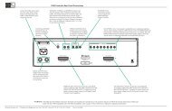
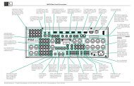
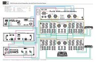
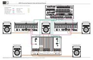
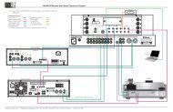
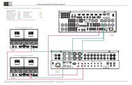
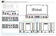
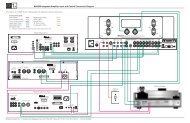
How to Connect for Center and Surround<strong>Channel</strong>sCaution: The supplied AC <strong>Power</strong> Cord should not beconnected to the Rear Panel of the <strong>MC303</strong><strong>Amplifier</strong> until after the Loudspeaker Connectionshave been made. Failure to observe thiscould result in Electric Shock. For additionalinstruction on making Loudspeaker Connectionscontact your <strong>McIntosh</strong> Dealer or <strong>McIntosh</strong>Technical Support.The connection instructions below, together with the<strong>MC303</strong> Connection Diagram located on the separate foldedsheet “Mc1A, is an example of a typical audio/video system.Your system may vary from this, however the actualcomponents would be connected in a similar manner. Foradditional information refer to “Connector and Cable Information”on page 4.1. For Remote <strong>Power</strong> Control, connect a power controlcable from the A/V Control Center or Preamplifier<strong>Power</strong> Control Out to the Right Front <strong>Channel</strong> <strong>Power</strong><strong>Amplifier</strong> <strong>Power</strong> Control In. Connect a second powercontrol cable from the Right Front <strong>Channel</strong> <strong>Power</strong><strong>Amplifier</strong> <strong>Power</strong> <strong>Power</strong> Control Out to the Left Front<strong>Channel</strong> <strong>Power</strong> <strong>Amplifier</strong> <strong>Power</strong> Control In.2. Connect a power control cable from the Left Front<strong>Channel</strong> <strong>Power</strong> <strong>Amplifier</strong> <strong>Power</strong> <strong>Power</strong> Control Out tothe <strong>MC303</strong> POWER CONTROL IN.3. Connect cables from the Balanced Outputs of the A/VControl Center or Preamplifier (Left and Right Front<strong>Channel</strong>s) to the Left and Right Front <strong>Power</strong> <strong>Amplifier</strong>s.Note: An optional hookup is to use the UNBALanced IN-PUTS with unbalanced cables instead of balanced.However, both type of connections for a given Inputshould not be used at the same time.4. Connect cables from the Balanced Outputs of the A/VControl Center or Preamplifier (Center and Surround<strong>Channel</strong>s) to the <strong>MC303</strong> BALANCED INPUTs (1-3).When connecting Loudspeakers to the <strong>MC303</strong> it is veryimportant to use cables of adequate size, so there is little tono power loss in the cables. The size is specified in GaugeNumbers or AWG (American Wire Gauge). The smallerthe Gauge number, the larger the wire size:Loudspeaker Cable Distance vs Wire Gauge GuideLoudspeakerImpedance25 feet(7.62 meters)or less50 feet(15.24 meters)or less100 feet(30.48 meters)or less2 Ohms 12AWG 10AWG 8AWG4 Ohms 14AWG 12AWG 10AWG8 Ohms 16AWG 14AWG 12AWG5. This <strong>McIntosh</strong> <strong>MC303</strong> <strong>Power</strong> <strong>Amplifier</strong> is designed forthe connection of a single Loudspeaker per amplifierchannel, with an impedance of 2 ohms, 4 ohms or 8ohms.Note: The remaining <strong>Amplifier</strong> Loudspeaker Terminalsshould not be connected to another Loudspeaker.6. Prepare the Loudspeaker Hookup Cables that attach tothe <strong>Amplifier</strong> by choosing one of the methods below:Bare wire cable ends:Carefully remove sufficient insulation from the cableends, refer to figures 1, 2 & 3. If the cable is stranded,carefully twistthe strands togetheras tightly as possible.Note: If desired, thetwisted ends canFigure 1 Figure 2 Figure 3be tinned with solder to keep the strands together,or attach spade lug and/or banana connector.Spade lug or prepared wire connection:Insert the spade lug connector or prepared section ofthe cable end into the terminal side access hole, andtighten the terminalcap until the cable isfirmly clamped intothe terminal so thewires cannot slip out. Refer to figures 4, 5 & 6.Banana plug connection:Figure 4 Figure 5 Figure 6Insert the banana plug into the hole at the top of theterminal. Refer to figures A and B.Note: BananaPlugs arefor use inthe UnitedStates andCanadaonly.7. Connect the Loudspeaker hookup cables from a singleLoudspeaker to the output terminals that match theimpedance of OUPUT 1, being careful to observe thecorrect polarities. Output impedance connections of 2ohms, 4 ohms and 8 ohms are provided. If the Loudspeaker’simpedance is in-between the available connections,use the nearest lower impedance connection.Refer to “General Information” Note 5 on page 3 foradditional information.WARNING: Loudspeaker terminals are hazardous liveand present a risk of electric shock.8. In a similar manner, connect a Loudspeaker to OUT-PUT 2 and connect the remaining Loudspeaker toOUTPUT 3.9. Connect the <strong>MC303</strong> <strong>Power</strong> Cord to a live AC outlet.8


![Product Brochure [pdf] - Audio Classics](https://img.yumpu.com/43032582/1/190x245/product-brochure-pdf-audio-classics.jpg?quality=85)