C48 Audio Preamplifier Owner's Manual - McIntosh
C48 Audio Preamplifier Owner's Manual - McIntosh
C48 Audio Preamplifier Owner's Manual - McIntosh

Create successful ePaper yourself
Turn your PDF publications into a flip-book with our unique Google optimized e-Paper software.
<strong>McIntosh</strong> Laboratory, Inc. 2 Chambers Street Binghamton, New York 13903-2699 Phone: 607-723-3512 www.mcintoshlabs.com<strong>C48</strong><strong>Audio</strong> <strong>Preamplifier</strong>Owner’s <strong>Manual</strong>
2The lightning flash with arrowhead, within an equilateraltriangle, is intended to alert the user to the presence ofuninsulated “dangerous voltage” within the product’s enclosurethat may be of sufficient magnitude to constitutea risk of electric shock to persons.WARNING - TO REDUCE RISKOF FIRE OR ELECTRICALSHOCK, DO NOT EXPOSETHIS EQUIPMENT TO RAIN ORMOISTURE.IMPORTANT SAFETYINSTRUCTIONS!PLEASE READ THEM BEFOREOPERATING THIS EQUIPMENT.1. Read these instructions.2. Keep these instructions.3. Heed all warnings.4. Follow all instructions.5. Do not use this apparatus near water.6. Clean only with a dry cloth.7. Do not block any ventilation openings. Installin accordance with the manufacturer’s instructions.8. Do not install near any heat sources such asradiators, heat registers, stoves, or other apparatus(including amplifiers) that produce heat.9. Do not defeat the safety purpose of the polarizedor grounding-type plug. A polarized plughas two blades with one wider than the other.A grounding type plug has two blades and aNO USER-SERVICEABLE PARTSINSIDE. REFER SERVICING TOQUALIFIED PERSONNEL.The exclamation point within an equilateral triangle isintended to alert the user to the presence of importantoperating and maintenance (servicing) instructions in theliterature accompanying the appliance.To prevent the risk of electricshock, do not remove cover orback. No user-serviceable partsinside.third grounding prong. The wide blade or thethird prong are provided for your safety. Ifthe provided plug does not fit into your outlet,consult an electrician for replacement of theobsolete outlet.10. Protect the power cord from being walked onor pinched particularly at plugs, conveniencereceptacles, and the point where they exitfrom the apparatus.11. Only use attachments/accessories specified bythe manufacturer.12. Use only with the cart, stand, tripod, bracket,or table specified by the manufacturer,or sold with the apparatus.When a cart is used, usecaution when moving the cart/apparatus combination to avoidinjury from tip-over.13. Unplug this apparatus during lightning stormsor when unused for long periods of time.14. Refer all servicing to qualified service personnel.Servicing is required when the apparatushas been damaged in any way, such as powersupplycord or plug is damaged, liquid hasbeen spilled or objects have fallen into theapparatus, the apparatus has been exposed torain or moisture, does not operate normally, orhas been dropped.15. Do not expose this equipment to dripping orsplashing and ensure that no objects filledwith liquids, such as vases, are placed on theequipment.16. To completely disconnect this equipment fromthe a.c. mains, disconnect the power supplycord plug from the a.c. receptacle.17. The mains plug of the power supply cord shallremain readily operable.18. Do not expose batteries to excessive heat suchas sunshine, fire or the like.19. Connect mains power supply cord only to amains socket outlet with a protective earthingconnection.
Thank YouYour decision to own this <strong>McIntosh</strong> <strong>C48</strong> <strong>Audio</strong> <strong>Preamplifier</strong>ranks you at the very top among discriminatingmusic listeners. You now have “The Best.” The<strong>McIntosh</strong> dedication to “Quality,” is assurance thatyou will receive many years of musical enjoymentfrom this unit.Please take a short time to read the information inthis manual. We want you to be as familiar as possiblewith all the features and functions of your new<strong>McIntosh</strong>.Please Take A MomentThe serial number, purchase date and <strong>McIntosh</strong> Dealername are important to you for possible insuranceclaim or future service. The spaces below have beenprovided for you to record that information:Serial Number:________________________________Purchase Date:_ _______________________________Dealer Name:_ ________________________________Technical AssistanceIf at any time you have questions about your <strong>McIntosh</strong>product, contact your <strong>McIntosh</strong> Dealer who is familiarwith your <strong>McIntosh</strong> equipment and any other brandsthat may be part of your system. If you or your Dealerwish additional help concerning a suspected problem,you can receive technical assistance for all <strong>McIntosh</strong>products at:<strong>McIntosh</strong> Laboratory, Inc.2 Chambers StreetBinghamton, New York 13903Phone: 607-723-3512Fax: 607-724-0549Customer ServiceIf it is determined that your <strong>McIntosh</strong> product is inneed of repair, you can return it to your Dealer. Youcan also return it to the <strong>McIntosh</strong> Laboratory ServiceDepartment. For assistance on factory repair returnprocedure, contact the <strong>McIntosh</strong> Service Departmentat:<strong>McIntosh</strong> Laboratory, Inc.2 Chambers StreetBinghamton, New York 13903Phone: 607-723-3515Fax: 607-723-1917Table of ContentsSafety Instructions...................................................... 2Thank You and Please Take a Moment...................... 3Technical Assistance and Customer Service.............. 3Table of Contents........................................................ 3General Information................................................... 4Connector and Cable Information.............................. 4Introduction................................................................ 5Performance Features................................................. 5Dimensions................................................................. 6Installation.................................................................. 7Connections:Rear Panel Connections............................................... 8(Separate Sheet)................................................... Mc2BConnecting Components............................................. 9Connection Diagrams(Separate Sheets).................. Mc1A, Mc1B and Mc2ARemote Control:Remote Control Push-buttons................................... 10How to use the Remote Control.................................11Front Panel:Front Panel Displays, Controls, Push-buttonsand Jack..................................................................... 12Setup:How to Operate the Setup Mode............................... 13Default Settings......................................................... 13Firmware Version...................................................... 13Source Inputs Reassignment..................................... 13Input Level Adjustment............................................. 14Display Brightness.................................................... 15Passthru..................................................................... 15Power Control Triggers 1 and 2................................. 16Comm Port Baud Rate............................................... 17Remote Control Codes.............................................. 17Operation:How to Operate the <strong>C48</strong>............................................ 18Trim Functions..................................................... 18-20Equalizer Bypass....................................................... 21Equalizer Controls..................................................... 22Passthru..................................................................... 22Optical and Digital Inputs......................................... 23USB Input Operation with a Computer..................... 23Additional Information:Photos...................................................................24-25Specifications............................................................ 26Packing Instruction................................................... 27Copyright 2010 © by <strong>McIntosh</strong> Laboratory, Inc.3
General Information and Connector InformationGeneral Information1. For additional connection information, refer to theowner’s manual(s) for any component(s) connectedto the <strong>C48</strong> <strong>Audio</strong> <strong>Preamplifier</strong>.2. The Main AC Power going to the <strong>C48</strong> and anyother <strong>McIntosh</strong> Component(s) should not be applieduntil all the system components are connectedtogether. Failure to do so could result in malfunctioningof some or all of the system’s normal operations.When the <strong>C48</strong> and other <strong>McIntosh</strong> Componentsare in their Standby Power Off Mode, theMicroprocessor’s Circuitry inside each componentis active and communication is occurring betweenthem.3. Balanced and Unbalanced Inputs and Outputs canbe mixed. For example, you may connect signalsources to Unbalanced Inputs and send signalsfrom the Balanced Outputs. You can also use Balancedand Unbalanced Outputs simultaneously,connected to different Power Amplifiers.4. The <strong>C48</strong> internal Digital to Analog ConverterCircuitry is designed to decode 2-channel PCM(Pulse Code Modulation) Digital Signal present atthe Coaxial and Optical Digital <strong>Audio</strong> Inputs. OtherDigital <strong>Audio</strong> Signal Format Types will cause the<strong>Audio</strong> Outputs of the <strong>C48</strong> to be muted and the FrontPanel Information Display will indicate an errormessage.5. The Remote Control Supplied with the <strong>C48</strong> IntegratedAmplifier is capable of operating othercomponents. For additional information go to www.mcintoshlabs.com.6. When discarding the unit, comply withlocal rules or regulations. Batteries shouldnever be thrown away or incinerated butdisposed of in accordance with the localregulations concerning battery disposal.7. For additional information on the <strong>C48</strong> and other<strong>McIntosh</strong> Products please visit the <strong>McIntosh</strong> WebSite at www.mcintoshlabs.com.Connector and Cable InformationXLR ConnectorsBelow is the Pin configuration for the XLR BalancedInput and Output Connectors on the <strong>C48</strong>. Refer to thediagrams for connections:PIN 1: Shield/GroundPIN 2: + OutputPIN 3: - OutputPIN 2 PIN 1PIN 3PIN 1 PIN 2PIN 3Power Control and Trigger ConnectorsThe <strong>C48</strong> Power Control Out, Trigger and Pass-ThruOutput Jacks send Power On/ Output 1&2, Trig 1&2and Pass-ThruOff Signals (+12 volt/0 volt)when connected to otherPower<strong>McIntosh</strong> Components. An Controladditional connection is forMeterIlluminationcontrolling the illumination ofControlthe Power Output Meters onGround<strong>McIntosh</strong> Power Amplifiers. A1/8 inch stereo mini phone plug is used for connectionto the Power Control, Trigger and Pass-Thru Outputson the <strong>C48</strong>.Note: The Power Control, Trigger, Pass-Thru and DataConnecting Cable is available from the <strong>McIntosh</strong>Parts Department:Power Control, Trigger, Pass-Thru and DataCable Part No. 170-202Six foot, shielded 2 conductor, with 1/8 inch stereomini phone plugs on each end.Data Port ConnectorsThe <strong>C48</strong> Data Out Ports send Remote Control Signalsto Source Components. A 1/8inch stereo mini phone plug isused for connection.DataSignalN/CDataGround4
Introduction and Performance FeaturesIntroductionThe <strong>McIntosh</strong> <strong>C48</strong> <strong>Audio</strong> <strong>Preamplifier</strong> is one of thefinest <strong>Preamplifier</strong>s ever created. The versatile <strong>Preamplifier</strong>provides connections for various input sourcesboth analog and digital. The <strong>C48</strong> Outputs have theability to drive multiple Power Amplifiers. The <strong>C48</strong>reproduction is sonically transparent and absolutelyaccurate. The <strong>McIntosh</strong> Sound is “The Sound of theMusic Itself.”Performance Features• Electromagentic Input Switching with Level TrimAdjustmentDigital Logic integrated circuits drive ElectromagneticSwitches on all Inputs and operating functionsfor reliable, noiseless, distortion free switching. Alleight Inputs on the <strong>C48</strong> can be matched in level, sothere are no abrupt changes in volume levels betweenthe different Inputs.• Moving Coil and Moving Magnet Phono InputsThe <strong>C48</strong> contains two different precision Phono <strong>Preamplifier</strong>Circuits. One for low output Moving CoilPhono Cartridges with selectable resistance loading,the other is for Moving Magnet Cartridges with selectablecapacitive loading. Both circuits use the latestdesigns to provide the lowest possible noise and distortion.The RIAA Correction Equalization Circuitryutilizes close tolerance resistors and capacitors for anextremely flat frequency response.• Digital <strong>Audio</strong> InputsThe <strong>C48</strong> has Coaxial, Optical and USB Digital Inputsto Decode PCM Signals from an external source. The<strong>C48</strong> Up Samples the Digital Signal to 192kHz with32Bit resolution before the Digital to Analog processbegins. The USB Input sends basic commands (e.g.Play/Pause, Next, Back, etc.) to the computer by usingthe <strong>C48</strong> Remote Control.• Balanced InputsThe Balanced Inputs allow the connection of a sourcecomponent using long cable lengths without a loss insound quality.• Precision Tracking Volume ControlVolume levels are controlled by a new Multi-StagePrecision Digitally Controlled Attenuator System witha tracking accuracy of 0.1dB.• Variable Rate Volume and Balance ControlsThe <strong>C48</strong> <strong>Preamplifier</strong>’s Volume and Balance ControlCircuitry provides an ideal rate of change with controlrotation.• Equalizer Controls with BypassThe Equalizer Circuitry provides 12dB of boost or cutat five different center frequencies. When an EqualizerControl is in the center position, all Circuit Componentsare removed from the Signal Path. The <strong>C48</strong>remembers the Equalizer Circuitry Bypass Option foreach input.• Pass-Thru ModeThe Automatic Pass-Thru Mode allows the <strong>C48</strong> to becomepart of a Multichannel Sound System for DVD-<strong>Audio</strong>, SACD and Home Theater Movies.• Alphanumeric Fluorescent DisplayThe Front Panel Information Display indicates theSource Selection, Volume/Balance Levels and SetupMode Selections. The display intensity is adjustable.• Remote Control with External Sensor InputThe Remote Control provides control of the <strong>C48</strong>operating functions and <strong>McIntosh</strong> Source Componentsconnected to it. Enjoy your <strong>McIntosh</strong> System fromanother room in your home by connecting an externalsensor.• Power Control Output and Trigger AssignmentA Power Control connection for convenient Turn-Onof <strong>McIntosh</strong> Power Amplifiers, Source Componentsand Accessories is included. The Power Control TriggerOuputs may be assigned to activate when a givenInput is selected.• Special Power SupplyFully regulated Power Supplies and a special R-CorePower Transformer ensure stable noise free operationeven though the power line varies.• Fiber Optic Solid State Front Panel IlluminationThe even Illumination of the Front Panel is accomplishedby the combination of custom designed FiberOptic Light Diffusers and extra long life Light EmittingDiodes (LEDs).• Glass Front Panel and Super Mirror ChassisFinishThe famous <strong>McIntosh</strong> Illuminated Glass Front Paneland the Stainless Steel Chassis with Super MirrorFinish ensures the pristine beauty of the <strong>C48</strong> will beretained for many years.5
DimensionsDimensionsThe following dimensions can assist in determiningthe best location for your <strong>C48</strong>. There is additionalinformation on the next page pertaining to installingthe <strong>C48</strong> into cabinets.Front View of the <strong>C48</strong>17-1/2"44.45cm5-3/8"13.69cm6"15.24cmSide View of the <strong>C48</strong>16-1/2"41.91cm14-1/2"36.83cmRear View of the <strong>C48</strong>17-1/8"43.50cm3/16"0.48cm4-13/16"12.22cm4-5/8"11.75cm13/16"2.06cm10-9/16"26.83cm2"5.08cm1-15/16"4.92cm13 -1/4"33.66cm6
InstallationInstallationThe <strong>C48</strong> can be placed upright on a table or shelf,standing on its four feet. It also can be custom installedin a piece of furniture or cabinet of yourchoice. The four feet may be removed from the bottomof the <strong>C48</strong> when it is custom installed as outlined below.The four feet together with the mounting screwsshould be retained for possible future use if the <strong>C48</strong>is removed from the custom installation and used freestanding. The required panel cutout, ventilation cutoutand unit dimensions are shown.Always provide adequate ventilation for your <strong>C48</strong>.Cool operation ensures the longest possible operatinglife for any electronic instrument. Do not install the<strong>C48</strong> directly above a heat generating component suchas a high powered amplifier. If all the components areinstalled in a single cabinet, a quiet running ventilationfan can be a definite asset in maintaining all thesystem components at the coolest possible operatingtemperature.A custom cabinet installation should provide thefollowing minimum spacing dimensions for cooloperation.Allow at least 2 inches (5.08cm) above the top, 2inches (5.08cm) below the bottom and 1 inch (2.54cm)on each side of the <strong>Preamplifier</strong>, so that airflow is notobstructed. Allow 20 inches (50.8cm) depth behind thefront panel. Allow 1-7/16 inch (3.66cm) in front of themounting panel for knob clearance. Be sure to cut outa ventilation hole in the mounting shelf according tothe dimensions in the drawing.<strong>C48</strong> Front PanelCustom Cabinet Cutout<strong>C48</strong> Side Viewin Custom Cabinet<strong>C48</strong> Bottom ViewCabinet Front PanelCabinetFrontPanelSupportShelf17-3/16"43.66cmCutout Opening for Ventilation9-1/8"23.18cm2-1/4"5.72cmin Custom Cabinet 15"Cutout38.10cmOpeningforVentilation4-7/8"12.38cmCutout Opening for Custom MountingChassisSpacers15"38.10cmNote: Center the cutout Horizontallyon the unit. For purposes ofclarity, the above illustrationis not drawn to scale.1-1/16"2.70cm12-5/16"31.27cm7
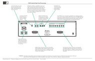
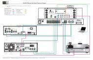
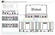
Rear Panel ConnectionsRear Panel ConnectionsThe identification of Rear Panel Connections for the<strong>C48</strong> <strong>Audio</strong> <strong>Preamplifier</strong> is located on a separate foldedsheet contained in the Owner’s <strong>Manual</strong> Packet.Refer to separate sheet “Mc2B” for the Rear PanelConnections.<strong>C48</strong> <strong>Audio</strong> Preamplifer Rear Panel8
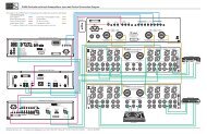
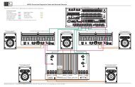
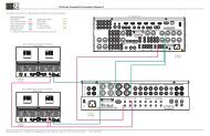
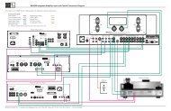
Connecting ComponentsConnecting ComponentsThe <strong>C48</strong> has the ability to automatically switch powerOn/Off to Source Components via the Power Controlconnections. The Data Port Connections allow forthe remote operation of basic functions using the <strong>C48</strong>Remote Control. With an external sensor connectedto the <strong>C48</strong>, remote control operation of the system ispossible from another room and/or when the <strong>C48</strong> islocated in a cabinet with the doors closed.The connection instructions below, together withthe <strong>C48</strong> Input/Output/Control Connection Diagramslocated on the separate folded sheets “Mc1A/1B andMc2A”, are an example of a typical audio system.Your system may vary from this, however the actualcomponents would be connected in a similar manner.For additional information refer to “Connector andCable Information” on page 4.Note: Source components may be connected to the<strong>C48</strong> Balanced Inputs or Digital Inputs instead ofUnbalanced Inputs. Refer to Setup “ReassigningInputs” to activate them on page 13.Power Control Connections:1. Connect a Control Cable from the <strong>C48</strong> POWERCONTROL MAIN Jack to the Power Control Inon the Turntable.2. Connect a Control Cable from the TurntablePower Control Out Jack to the SACD/CD PlayerPower Control In Jack.3. Connect a Control Cable from the SACD/CDPlayer Power Control Out Jack to the Tuner PowerControl In Jack.4. Connect a Control Cable from the Tuner PowerControl Out Jack to the Music Server Power ControlIn Jack.5. Connect a Control Cable from the <strong>C48</strong> POWERCONTROL OUTPUT 1 Jack to the Power AmplifierPower Control In Jack.Note: If two Power Amplifiers are used, connect thePower Control Output of the first Amplifier tothe Power Control Input on the second Amplifier.6. Optionally connect a Control Cable from the <strong>C48</strong>POWER CONTROL OUTPUT 2 Jack to thePower Amplifier (Secondary Room) Power ControlIn Jack.7. Connect any additional Components in a similarmanner, as outlined in steps 1 thru 4.Data Control Connections:8. Connect a Control Cable from the <strong>C48</strong> TUNERDATA PORTS Jack to the TUNER Data In Jack.9. Connect a Control Cable from the <strong>C48</strong> CD DATAPORT Jack to the SACD/CD Player Data In Jack.10. Connect a Control Cable from the <strong>C48</strong> SRVRDATA PORT Jack to the Music Server Data InJack.11. Connect any additional <strong>McIntosh</strong> Components in asimilar manner, as outlined in steps 8 thru 10.Sensor Connection:12. Connect a Control Cable from the <strong>C48</strong> IR InputConnector to the external Sensor.<strong>Audio</strong> Connections:13. Connect an <strong>Audio</strong> Cable from the <strong>C48</strong> TUNERINPUT Jacks to the Tuner (Fixed) Output Jacks.14. Connect an <strong>Audio</strong> Cable from the <strong>C48</strong> CD IN-PUT Jacks to the SACD/CD Player (Fixed) OutputJacks.15. Connect an <strong>Audio</strong> Cable from the <strong>C48</strong> SRVR IN-PUT Jacks to the Music Server Output Jacks.16. Connect an <strong>Audio</strong> Cable from the <strong>C48</strong> RECORDOUTPUT Jacks to the Music Server Input 3 Jacks.17. Connect the <strong>Audio</strong> Cables coming from the Turntableto the <strong>C48</strong> MC PHONO INPUT Jacks.Note: If the Turntable has a Moving Magnet Cartridgeconnect the audio cables to the <strong>C48</strong> MMPHONO INPUT instead of the MC Input.18. Connect Balanced Cables from the <strong>C48</strong> BALancedOUTPUT 1 connectors to the Power AmplifiersBalanced (Left and Right) Inputs.19. Optionally Connect an <strong>Audio</strong> Cable from the <strong>C48</strong>BALanced OUTPUT 2 connectors to the PowerAmplifier (Secondary) Inputs.20. Connect any additional <strong>McIntosh</strong> Components in asimilar manner, as outlined in steps 14 thru 18.Optional “PassThru” Connections:21. Connect Balanced Cables from the A/V ControlCenter Front Left and Right Channel BalancedOutput connectors to the BALanced 2 Input connectors.Note: Refer to Setup “PassThru” on page 15 to activatethe BALanced 2 Input.22. Connect a Control Cable from the <strong>C48</strong>PASSTHRU to A/V Control Center Zone ZAPower Control Output.Optional USB Connection:23. Connect a USB cable with (type A to type B) connectorsfrom the <strong>C48</strong> USB D/A Input to an availableUSB connector.Ground Connections:24. Connect the Ground Cable coming from the Turntableto the <strong>C48</strong> GND Binding Post.AC Power Cords Connections:25. Connect the <strong>C48</strong> and any remaining components’AC Power Cords to a live AC outlet as illustrated.9
Remote Control Push-ButtonsLED illuminates during the time aremote command is sent to the <strong>C48</strong>Switches the Trigger 1 and/or 2Power Control Jack(s) On/Off, referto “Setup, Power Control TRIG 1and TRIG 2” on page 15 for additionalinformationSelects a Disc Player, Music Serveror Recorder Function. Seek StationsUp or Down the AM/FM Dial.Select AM/FM Station Presets andperforms various functions on avariety of <strong>McIntosh</strong> ComponentsDisplays On Screen Functions on the<strong>McIntosh</strong> Music Server and a varietyof other <strong>McIntosh</strong> ComponentsAdjusts the volume level up or downPress to Power the <strong>C48</strong> ONPress to Power the <strong>C48</strong> OFFPress to change broadcast bands onan external <strong>McIntosh</strong> Tuner connected.Select certain functions on avariety of <strong>McIntosh</strong> ComponentsSelects On Screen Functions on avariety of <strong>McIntosh</strong> ComponentsPress TRIM and then the LEVELPush-buttons to select and adjustvarious functionsMutes the audioSelects AM Tuner OperatingFunctions and Disc Selection oncertain <strong>McIntosh</strong> Disc PlayersFunctions as a “shift” key whenused with the AM or FM pushbuttonsto select Output 1 or 2Scrolls through theavailable <strong>C48</strong> InputsSelects FM Tuner Operating Functionsand Track Selection on certain<strong>McIntosh</strong> CD PlayersUse to select tuner presets, disctracks or any numbered operationScrolls through theavailable <strong>C48</strong> InputsSelects one of the eightavailable <strong>Audio</strong> SourcesNote: Push-buttons whose function is not identified above are for use with other <strong>McIntosh</strong> Products.10
How to use the Remote ControlHow to use the Remote ControlThe supplied HR072 Remote Control is capable ofdirectly controlling the functions of contemporarySource Components connected to the <strong>C48</strong> via the DataPorts.Note: If at any time the <strong>C48</strong> seems unresponsive toHR072 Remote Control Commands press thePush-button first.Input Source SelectionPress the appropriate Source Push-button to select thedesired program source.Note: When the C50 is Off, pressing one of the SourcePush-buttons will switch the C50 On and will go tothat Input.MutePress the MUTE Push-button to mute the audio in alloutputs except the REC OUTPUT. The word MUTEwill appear on the Front Panel Information Display.To un-mute the audio, press the MUTE Push-buttonagain.Disc, Server and Tape FunctionsUse these push-buttons to operate a DVD Player, CDPlayer, CD Changer, Music Server or Recorder.Numbered Push-buttonsPress Push-buttons 0 through 9 to access tuner stationpresets, tracks on discs or selections on a MusicServer.Disc and TrackUse the AM (disc) and FM (track) Push-buttons whena Disc Player or Music Server is being used.Tuner Push-buttonsPress the AM or FM Push-button to select the desiredbroadcast band. Press and release the Channel Up por Down q Push-button to seek the next availablestation. Press and hold a Channel Up p or Down qPush-button to seek continuously from station to station.VolumePress the Up p or Down q VOLUME Push-button toraise or lower the listening volume level.Note: The Record Signals present at REC OUTPUTS arenot affected by volume changes.PausePress the Pause Push-button to perform variousfunctions on a variety of <strong>McIntosh</strong> Components. Itwill also pause the playing of a disc or tape player.TrimPress the TRIM Push-button until the desired Trimfunction (Balance, Trim Level, etc.) appears on theFront Panel Information display, then press the LEV-EL Up p or Down q Push-button to adjust the Trimsetting.Note: Press the TRIM Push-button to recall the last Trimfunction selected. For additional information onthe Trim Functions refer to pages 18, 19 and 20.Amplifier SelectionPress the BLUE (Setup) Push-button followed by theAM (Output 1) or FM (Output 2) Push-button, to controlthe rear panel <strong>Audio</strong> OUTPUTS 1, 2 (ON or OFF)and Power Control OUTPUT 1 / OUTPUT 2. TheseOUTPUTS provide signals to a Power Amplifier orother accessory component.11
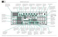
Front Panel Displays, Controls, Push-buttons and JackIR Sensor receivescommands from aRemote ControlEQUALIZER Controls increaseor decrease the volume levels atthe Center Frequencies of 30Hz,125Hz, 500Hz, 2,000Hz, and10,000HzINPUT Control allowsthe selection ofvarious sources forlistening and recordingVOLUME Controlallows adjustmentof the listening levelfor both channelsConnection for lowimpedance dynamicheadphones, forprivate listeningSTANDBY/ONPush-button withindicator, switchesthe <strong>C48</strong> ON or OFF(Standby) and resetsthe microprocessorsMONO with indicator,combines the Left andRight Channel signals forMonophonic SoundEQualizer BYPASSPush-button with indicator,when activated theaudio signal bypasses theEqualizer Controls, alsoused to enter and exit theSetup ModeTRIM Push-buttonwith indicator, allowsselection of varioustypes of settingsINFORMATION DISPLAYindicates the Sources, Volume,other <strong>Audio</strong> Settings,Operational Functions andSetup Mode SettingsMUTE Push-buttonmutes the audio fromthe Loudspeakers andHeadphonesOUTPUT 1 and 2Push-buttons withindicators, switch the<strong>Preamplifier</strong> Outputs1 and 2 On or Off12
SetupHow to Operate the Setup ModeYour <strong>McIntosh</strong> <strong>C48</strong> has been factory configured fordefault operating settings that will allow immediateenjoyment of superb audio without the need for furtheradjustments. If you wish to make changes to thefactory default settings, a Setup Feature is provided tocustomize the operating settings using the Front PanelInformation Display. Refer to the <strong>C48</strong> Front PanelIllustration on the previous page while performing thefollowing steps.Note: If the <strong>C48</strong> is currently On, proceed to step 2.1. Press the STANDBY/ON Push-button on the FrontPanel or press the (Power) Push-button on theRemote Control to switch On the <strong>C48</strong>. The <strong>C48</strong>will go through a brief startup intialization withthe Front Panel Information Display indicating thelast used source and volume setting, this is followedby the volume setting indication starting atzero and then increasing to the last used volumesetting. Refer to figure 1.SOURCE: TUNER15%Figure 12. Press and hold the EQ BYPASS/SETUP Pushbuttonuntil the Front Panel Information Displayindicates “<strong>McIntosh</strong> <strong>C48</strong>, V1.00 - 1.0 or higherFirmware. Refer to figure 2. At this time the LED<strong>McIntosh</strong> <strong>C48</strong>V1.00 - 1.0Figure 2above the TRIM Push-button will be illuminated.3. Press the OUTPUT 2 / MENU ► Push-button toselect the next Setup Mode Menu item, “SETUP:SORCE INPUT, TUNER : RCA”. With eachadditional press of the OUTPUT 2 / MENU ►Push-button the Setup Menu will advance to thenext Menu Selection. Refer to figure 3.4. To exit from the Setup Mode, press the EQ BY-PASS/SETUP Push-button. The LED above theTRIM Push-button will extinguish and the FrontPanel Display will revert back to its normal display.Refer to figure 1.Default SettingsThe Default Settings Chart below indicates the FunctionName, Default Setting and the Page Number foradditional information.Default SettingsFunction Name Setting Page No.<strong>McIntosh</strong> <strong>C48</strong> V_._ _ - _._ 13SOURCE INPUT(connector type)LEVEL(Trim)DISPLAY (Brightness)RCA 130.0dB 143 15PASSTHRU OFF 15TRIG 1 Output(Action)TRIG 2 Output(Action)COMM PORT(Baud Rate)REMOTE(Codes)SETUP: SOURCE INPUTTUNER : RCAFigure 3MAIN 16MAIN 16115200 17NORM 17Firmware VersionThe <strong>C48</strong> functionality is controlled by internal softwarethat is know as Firmware. The Version of theFirmware in the <strong>C48</strong> can be identified at any time byutilizing the Setup Mode.1. Press and hold the <strong>C48</strong> Front Panel EQ BYPASS/SETUP Push-button to enter the Setup Mode.2. The number after the character “V” is the Firmwarenumber. Refer to figure 2.3. To exit the Setup Mode, press the EQ BYPASS/SETUP Push-button.Source Inputs ReassignmentThe <strong>C48</strong> provides the ability to reassign the non-Phono Inputs (High Level) to either one of two BalancedInputs or one of the four Digital Inputs.In the first example, the CD2 Input will be reassignedfrom the unbalanced CD2 (RCA Jacks) to the BAL-ANCED 1 (XRL Connector).Notes: 1. Any one of the Default Inputs may be swichedOff. If any input is switched Off its name willno longer appear on the Front Panel InformationDisplay when using the INPUT Control,nor is it accessible with the Remote Control.2. The Phono MC (Moving Coil) and MM (MovingMagnet) Input are designed for connectionof a turntable only and thus non-reassignable.However, the Phono Inputs may be switchedOff.3. Only one Input may be assigned at a time to aBalanced (1 & 2) or Digital (1 thru 4) Connector.If an already assigned Balanced or Digitalconnector is to be reassigned to a differentInput, the Input currently assigned to the connectorfirst needs to be changed. It can be setto a RCA connector or to another availableBalanced or Digital connector.13
Reassign Source Inputs, con’t1. Press and hold the EQ BYPASS/SETUP Pushbuttonuntil the Setup Mode is active. Then pressthe OUTPUT 2 / MENU ► Push-button to selectthe Setup Menu item “SETUP: SOURCE INPUT,TUNER :RCA”. Refer to figure 4.SETUP: SOURCE INPUTTUNER : RCAFigure 42. Rotate the INPUT Control until “CD2 : RCA”appears on the Front Panel Information Display.Refer to figure 5.SETUP: SOURCE INPUTCD2 : RCAFigure 53. Rotate the VOLUME/ADJUST Control until “CD2: BALANCED 1” appears on the Front Panel InformationDisplay. Refer to figure 6.SETUP: SOURCE INPUTCD2 : BALANCED 1Figure 6The second example will illustrate reassigning theSRVR (Server) Input from SRVR/REC Input (RCAJacks) to the DIGital 1 Optical Input.4. Rotate the INPUT Control until “SRVR : RCA”appears on the Front Panel Information Display.Refer to figure 7.SETUP: SOURCE INPUTSRVR : RCAFigure 75. Rotate the VOLUME/ADJUST Control until“SRVR : DIGITAL 1” appears on the Front PanelInformation Display. Refer to figure 8. RecordSETUP: SOURCE INPUTSRVR : DIGITAL 1Figure 8any changes made to the various inputs from thedefault settings in the “Input and Power ControlSettings” chart for future reference.6. To exit from the Setup Mode, press the EQ BY-PASS/SETUP Push-button.Input Level AdjustmentSource Components can have slightly different volumelevels resulting in the need to readjust the <strong>C48</strong> VolumeControl when switching between different sources.The <strong>C48</strong> allows the adjustment of levels for each ofthe Source Inputs for the same relative volume. TheCD and SERVER Inputs are used in the followingexample.Note: The range of adjustment is ± 6dB. The signal Levelpresent at the RECORD OUT Jacks is unaffectedby any changes in the Setup Level adjustment. Thelevel adjustments made are retained in permanentmemory. They can be changed during operationof the <strong>C48</strong> by performing a Trim Level Procedure,refer to page 19 for additional information.1. Rotate the INPUT Control to select the CD Inputand adjust the VOLUME Control to the desiredlistening level.2. Press and hold the EQ BYPASS/SETUP Pushbuttonuntil the Setup Mode is active. Then pressthe OUTPUT 2 / MENU ► Push-button until theSetup Menu item “LEVEL: CD 0.0dB” appearson the Front Panel Information Display. Refer tofigure 9.LEVEL: CDMin ||Figure 90.0dBMaxNote: The CD Input is serving as a reference levelor choose another source frequently listenedto. The Input Source should be set to a referenceLevel (Trim) of 0.0dB.3. Rotate the INPUT Control until “LEVEL: SRVR0.0dB” appears on the Front Panel InformationDisplay. If necessary, rotate the VOLUME/AD-JUST Control to obtain the same volume levelas the CD Input by switching between the twoInputs using the INPUT Control.14
Setup, con’t4. Rotate the INPUT Control until “LEVEL: SRVR_._” appears on the Front Panel InformationDisplay. The illustration in figure 10 indicates a-2.5dB decrease in the SRVR Level to match thevolume level of the CD Input.5. Repeat step 4 for other Inputs with componentsources connected until they all have the samerelative volume levels. Record any changes madeto the various inputs from the default settingsin the “Input and Power Control Settings” chartbelow.6. To exit from the Setup Mode, press the EQ BY-PASS/SETUP Push-button.Input NameTUNERCDCD2DVDAUXSRVR (Rec)PHONO MCPHONO MMLEVEL: SRVRMin ¦ ¦ ¦Input and Power Control SettingsConnectionTypeFigure 10New Level(Trim)-2.5dBMaxTriggers1 2Display BrightnessThe Front Panel Information Display Brightness maybe changed from the default setting. There are fourbrightness settings for the Information Display. TheDisplay Brightness setting may be varied 1 (Dim) to4 (Bright). Follow the steps below for reducing theDisplay Brightness.1. Press and hold the EQ BYPASS/SETUP Pushbuttonuntil the Setup Mode is active. Then pressthe OUTPUT 2 / MENU ► Push-button until theSetup Menu item “SETUP: DISPLAY” appearson the Front Panel Information Display. Refer tofigure 11.SETUP: DISPLAYBRIGHTNESS: 3Figure 112. Rotate the VOLUME/ADJUST Control until“BRIGHTNESS: 1” appears on the Front PanelInformation Display. Refer to figure 12.SETUP: DISPLAYBRIGHTNESS: 1Figure 123. To exit from the Setup Mode, press the EQ BY-PASS/SETUP Push-button.PassthruThe <strong>C48</strong> can be part of a Multichannel Sound Systemfor SACD, DVD-<strong>Audio</strong> and Home Theater. The Rightand Left Front Channels from an <strong>Audio</strong>/Video ControlCenter or Surround Decoder can “Passthru” the <strong>C48</strong>and onto its associated Power Amplifier(s). The SetupMode allows the activation of the Passthru Mode andthe selection of the specified <strong>C48</strong> Input Connector tobe used for the Right and Left Front Channels. In theexample below, the Right and Left Front Channelsfrom the <strong>Audio</strong>/Video Control Center will be connectedto the BALanced 2 Input Connectors on the <strong>C48</strong>.Refer to page 9 for additional connection information.Notes: 1. The Phono Input Connectors and Digital InputConnectors are not assignable as a PassthruInput.2. If Balanced Input Connectors 1 and/or 2 arealready reassigned to a given Input, they willnot appear in the list of available Inputs for thePassthru Mode.3. When one of the RCA Inputs is selected as aPassthru Input, it is advisable to remove itfrom the list of available Inputs by switchingit Off. Refer to “Source Inputs Reassignment”starting on page 13.1. Press and hold the EQ BYPASS/SETUP Pushbuttonuntil the Setup Mode is active. Then pressthe OUTPUT 2 / MENU ► Push-button until theSetup Menu item “SETUP: PASSTHRU, Source:OFF” appears on the Front Panel AlphanumericDisplay. Refer to figure 13.SETUP: PASSTHRUSource: OFFFigure 132. Rotate the VOLUME/ADJUST Control until“SETUP: PASSTHRU, Source: BALANCED 2”15
Passthru, con’tappears on the Front Panel Alphanumeric Display.Refer to figure 14.SETUP: PASSTHRUSource: BALANCED 2Figure 143. Press the EQ BYPASS/SETUP Push-button to exitthe Setup Mode.Power Control Triggers 1 and 2By default the Power Control TRIGger 1 and TRIGger2 Outputs function the same as the MAIN PowerControl Jack, switching On/Off with the <strong>C48</strong>. Trigger1 and 2 are also reassignable to activate when the ACCON/OFF Push-buttons on the Remote Control are usedor when a given Input or Inputs are selected.In the first example, the Power Control Trigger 1Output will be set to function via the Remote ControlACC Push-buttons.1. Press and hold the EQ BYPASS/SETUP Pushbuttonuntil the Setup Mode is active. Then pressthe OUTPUT 2 / MENU ► Push-button until theSetup Menu item “SETUP: TRIG1 OUTPUT, Action:MAIN” appears on the Front Panel InformationDisplay. Refer to figure 15.SETUP: TRIG1 OUTPUTAction: MAINFigure 152. Rotate the VOLUME/ADJUST Control until “Action:REMOTE” appears. Refer to figure 16.SETUP: TRIG1 OUTPUTAction: REMOTEFigure 163. Press the EQ BYPASS/SETUP Push-button to exitthe Setup Mode.The second example will use selection of the TunerInput to switch the Trigger 1 Output On.4. Press and hold the EQ BYPASS/SETUP Pushbuttonuntil the Setup Mode is active. Then pressthe OUTPUT 2 / MENU ► Push-button until theSetup Menu item “SETUP: TRIG1 Output, Action:MAIN” appears on the Front Panel InformationDisplay. Refer to figure 15.5. Rotate the VOLUME/ADJUST Control until “Action:SOURCE” appears. Refer to figure 17.SETUP: TRIG1 OUTPUTAction: SOURCEFigure 176. Then press the OUTPUT 2 / MENU ► Pushbuttonuntil the Setup Menu item “SETUP: TRIG1OUTPUT, Source: _ _ _ _ _ _ _ _ OFF” appearson the Front Panel Information Display. Refer tofigure 18.Note: By default all the Source Inputs are set to Off.7. Rotate the INPUT Control to select the Tuner asthe source. Refer to figure 18.SETUP: TRIG1 OUTPUTSource: Tuner OFFFigure 188. Rotate the VOLUME/ADJUST Control until“Source: Tuner ON” appears. Refer to figure 19.SETUP: TRIG1 OUTPUTSource: Tuner ONFigure 199. Press the EQ BYPASS/SETUP Push-button to exitthe Setup Mode.16
Setup, con’tComm Port Baud RateThe <strong>C48</strong> may be remotely controlled from otherequipment connected to the Rear Panel RS232C connector.The speed at which the <strong>C48</strong> communicates(8 bit, no parity and 1 stop bit) with other equipmentis adjustable from 9,600 bits per second to 115,200bits per second. To change from the default speed of115,200 bits per second, perform the following steps:1. Press and hold the EQ BYPASS/SETUP Pushbuttonuntil the Setup Mode is active. Then pressthe OUTPUT 2 / MENU ► Push-button until theSetup Menu item “SETUP: COMM PORT BAUDRATE: 115200” appears on the Front Panel InformationDisplay. Refer to figure 20.SETUP: COMM PORTBAUD RATE: 115200Figure 202. Rotate the VOLUME/ADJUST Control to selectthe desired speed.3. Press the EQ BYPASS/SETUP Push-button toexit the Setup Mode.Remote Control CodesThe Remote Control included with the <strong>C48</strong> utilizes theNORMal <strong>McIntosh</strong> Control Codes. The Second Set ofControl Codes the <strong>C48</strong> will respond to is referred to asthe ALTernate Codes. The ALTernate Codes are usedwhen the <strong>C48</strong> is used in the same location as another<strong>McIntosh</strong> <strong>Preamplifier</strong> and/or A/V Control Center.This will prevent the Remote Control from affectingthe operation of both units at the same time. To activatethe Remote Control ALTernate Codes performthe following steps:1. Press and hold the EQ BYPASS/SETUP Pushbuttonuntil the Setup Mode is active. Then pressthe OUTPUT 2 / MENU ► Push-button until theSetup Menu item “SETUP: REMOTE, CODES:NORM” appears on the Front Panel InformationDisplay. Refer to figure 21.SETUP: REMOTECODES: NORMFigure 212. Rotate the VOLUME/ADJUST Control until“CODES: ALT” appears on the Front Panel InformationDisplay. Refer to figure 22.SETUP: REMOTECODES: ALTFigure 223. Press the EQ BYPASS/SETUP Push-button toexit the Setup Mode.4. To change the <strong>C48</strong> Remote Control to the AlternateCodes perform the following steps:A. Press the “Mc” Push-button.B. Press the SET Push-button until the “Mc” Pushbuttonflashes twice.C. Press the 3, 2, 4, 2 and 9 Push-buttons within 5seconds.D. The “Mc” Push-button flashes twice.Note: To reset the Remote Control to normalcodes perform steps A and B then enter3, 2, 4, 2 and 8 for step C.5. Press the VOLUME UP/DOWN Push-button onthe Remote Control to verify proper operation.17
How to Operate the <strong>C48</strong>Power On and OffThe Red LED above the STANDBY/ON Push-buttonlights to indicate the <strong>C48</strong> is in Standby mode. Toswitch ON the <strong>C48</strong>, press the STANDBY/ON Pushbuttonon the Front Panel or the (Power On)Push-button on the Remote Control. The <strong>C48</strong> will gothrough a brief startup initialization with the FrontPanel Information Display indicating the last usedsource and volume setting, this is followed by thevolume setting indication starting at zero and thenincreasing to the last used volume setting. Refer tofigures 50, 51, 52 and 53. To switch OFF the <strong>C48</strong> pressthe STANDBY/ON Push-button on the Front Panel orthe OFF Push-button on the Remote Control.Note: For an explanation of the Remote ControlPush-button functions, refer to pages 10 and 11.SOURCE: CD115%Figure 51SOURCE: SERVER30%Figure 52Source SelectionRotate the INPUT Control to select the desired sourceor press the appropriate push-button on the RemoteControl. Refer to figures 50 and 53.Volume ControlRotate the Front Panel VOLUME Control or use theVOLUME Upp or Downq Push-buttons on the RemoteControl for the desired listening level. Refer tofigures 50 and 53.Trim FunctionsThe <strong>C48</strong> has seven different Trim Selections withAdjustments. The Trim Selections include Balance,Trim Level, Amplifier Meter Backlight, EqualizerMode, Mono/Stereo Mode, Digital <strong>Audio</strong> Display Infoand Phono Cartridge Loading. The Trim Settings arestored in memory independentlyfor each Input SourceSelected, except the AmplifierIllumination and Digital<strong>Audio</strong> Display settings of On orOff, which are the same for allinputs.Note: Selection and Adjustmentof all Trim Functions maybe performed using theFront Panel TRIM, OUT-PUT 1/ OUTPUT 2 / ◄MENU ► Push-buttonstogether with the VOL-UME/ADJUST Control.The Remote Control TRIMPush-Button together withthe LEVEL + / - Pushbuttonmay also beused. Refer to figures 50and 53.BALANCEListening balance varies withdifferent program sources,room acoustics and listeningpositions relative to the Loudspeakers.Use the Balance(Trim Function) as needed toachieve approximately equallistening volume levels in eachLoudspeaker. To adjust the Bal-Figure 53Figure 50BALANCE: 0 dB||Figure 5418
How to Operate the <strong>C48</strong>ance perform the following:1. Press the TRIM Push-button repeatedly on theRemote Control until “BALANCE 0 dB” appearson the Front Panel Information Display. Refer tofigure 54.Note: The Front Panel TRIM Push-button togetherwith the OUTPUT 1/ OUTPUT 2 / ◄ MENU ►Push-buttons may also be used.2. Rotate the VOLUME/ADJUST Control or press theLEVEL + / - Push-buttons on the Remote Controlto emphasize the Right Channel (refer to figure 55)or the Left Channel (refer to figure 56).BALANCE: 50 dB¦ ¦ ¦ ¦ ¦ ¦ ¦ ¦ ¦ ¦Figure 55BALANCE: 50 dB¦ ¦ ¦ ¦ ¦ ¦ ¦ ¦ ¦ ¦Figure 56The Front Panel Display indicates the Balance changesin steps from 0 to 50dB. After approximately 4seconds the Information Display returns to indicatethe Source Selection and Volume Level. To verify theBalance setting without changing it, use the TRIMPush-button and select Balance.TRIM LEVELThe Trim Level adjustments allow for making fineadjustments to the previously performed Trim LevelAdjustments (refer to the Setup Section of this Owner’s<strong>Manual</strong> on page 14 for additional information). Tomake a fine adjustment to the currently selected InputSource perform the following:1. Select “TRIM LEVEL” as indicated on the FrontPanel Information Display. Refer to figures 50, 53and 57.TRIM LEVEL:Min ||Figure 572. Adjust the Trim Level to -2.5dB. Refer to figure58.TRIM LEVEL:Min ¦ ¦ ¦Figure 580.0dBMax-2.5dBMaxAfter approximately 4 seconds the InformationDisplay returns to indicate the Source Selection andVolume Level.METER ILLUMINATIONThe Front Panel Meter Illumination of recent <strong>McIntosh</strong>Power Amplifiers may be switched On or Off byperforming the following:1. Select “AMP METER BACKLIGHT, Lights: On”as indicated on the Front Panel Information Display.Refer to figures 50, 53 and 59.AMP METER BACKLIGHTLights: OnFigure 592. Switch On or Off the Amplifier Meter Illumination.Refer to figure 60.AMP METER BACKLIGHTLights: OffFigure 60After approximately 4 seconds the InformationDisplay returns to indicate the Source Selection andVolume Level.EQUALIZER MODEThe built-in five band Frequency Equalizer providesmore precise adjustment of sound than Bass andTreble Controls. By default the Equalizer is active forall Input Sources however, any Input Source may beassigned to bypass the Equalizer. To bypass the Equalizerfor a given Input Source, perform the followingsteps:Note: The audio signal present at the RECORD OUTJacks is unaffected by the Equalizer settings.1. Select the desired Input Source.2. Select “EQUALIZER MODE, ______: Enable” asindicated on the Front Panel Information Display.Refer to figure 61.EQUALIZER MODETUNER : EnableFigure 613. Set the EQUALIZER MODE to be either enabledor bypassed. Refer to figure 62.EQUALIZER MODETUNER : BypassFigure 62After approximately 4 seconds the InformationDisplay returns to indicate the Source Selection andVolume Level.MONO/STEREO MODEBy default the Stereo Mode is active for all InputSources however, any Input Source may be assignedto Mono Mode. To change Stereo Mode to Mono for agiven Input Source, perform the following steps:Note: The audio signal present at the RECORD OUTJacks is unaffected by the Stereo/Mono setting.19
How to Operate the <strong>C48</strong>, con’t1. Select the desired Input Source.2. Select “MONO/STEREO MODE, ______: Stereo”as indicated on the Front Panel InformationDisplay. Refer to figure 63.MONO / STEREO MODETUNER : StereoFigure 633. Set the “MONO/STEREO MODE” for either STE-REO or MONO. Refer to figure 64.MONO / STEREO MODETUNER : MonoFigure 64After approximately 4 seconds the InformationDisplay returns to indicate the Source Selection andVolume Level.DIGITAL AUDIO DISPLAYBy default the Digital <strong>Audio</strong> Display is switched Off.To display information about the type of digital signalpresent when any one of the five digital inputs is selected,perform the following steps:1. Select one of the Inputs assigned to an active digitalsource.Note: The USB-D/A Input may also be selected whenthe <strong>C48</strong> is connected to a computer.2. Select “DIGITAL AUDIO, Display Info: Off” asindicated on the Front Panel Information Display.Refer to figure 65.DIGITAL AUDIODisplay Info : OffFigure 653. Set the “DIGITAL AUDIO, Display Info” to On.Refer to figure 66.DIGITAL AUDIODisplay Info : OnFigure 66After approximately 4 seconds the InformationDisplay will return to indicate the Source Selection,Volume Level and the Digital Information. Refer tofigure 67.SOURCE: DVD15% 2CH PCMFigure 67PHONO ADJUSTMENTSWhen the Phono MC or Phono MM Input is selectedan additional TRIM SELECT FUNCTION becomesavailable for adjustment. Perform the following stepsto make the Phono Trim Adjustments:1. Select either the Phono MM or Phono MC SourceInput.2. Select “PHONO CARTRIDGE, Moving Coil 500Ohm” or “PHONO CARTRIDGE, Moving Magnet50pF” as indicated on the Front Panel InformationDisplay. Refer to figures 68 and 69.PHONO CARTRIDGEMoving Coil: 500 OhmFigure 68PHONO CARTRIDGEMoving Magnet: 50pFFigure 693. Set the desired phono cartridge loading value(Ohms for a Moving Coil Cartridge or Capacitancefor a Moving Magnet Cartridge) that comesclosest to the Phono Cartridge Makers recommendedvalue.After approximately 4 secondsthe Alphanumeric Displayreturns to indicate the SourceSelection and Volume Level.MonoPress the Front Panel MONOPush-button to change fromStereo to Mono Mode forthe currently selected InputSource. The LED above theMONO Push-button will illuminate.Refer to figure 50.The <strong>C48</strong> remembers for eachselected Input whether theMode is Stereo or Mono. Tochange the Mode from Monoto Stereo for the currentlyselected Input Source press theMONO Push-button.Note: The audio signalpresent at the RE-CORD OUT Jacksis unaffected by theMONO Push-button.Equalizer BypassPress the Front Panel EQBYPASS Push-button toremove the <strong>C48</strong> EqualizerCircuitry from the signal pathfor the currently selected Input Figure 53Source. The LED above theEQ BYPASS Push-button will illuminate. Refer tofigure 50. The <strong>C48</strong> remembers for each selected Inputwhether the Equalizer Circuitry is deactivated. To re-20
How to Operate the <strong>C48</strong>, con’tThe illustration to the right shows the fundamentalfrequency range of acoustical musical instruments andthe human voice. It also shows the range of adjustmentof frequencies for each of the Equalizer Controls ofthe <strong>C48</strong> at the +6dB and -6dB points.PassthruWhen the <strong>C48</strong> is connected together with a <strong>McIntosh</strong>Multichannel A/V Control Center or Surround Decoderand has the PASSTHRU MODE activated, it willautomatically turn-on when the A/V Control Centeror Surround Decoder is turned On. It will indicate onthe Front Panel Alphanumeric Display “PASSTHRU”.Refer to figure 71.PASSTHRUFundamental Frequencies of Acoustical Musical Instruments and the Human VoiceSOPRANOCONTRALTOTENORSINGING VOICEBARITONEBASSPICCOLOFLUTEOBOEENGLISH HORNB CLARINETWOODWINDSBASS CLARINETALTO SAXOPHONE IN BBASSOONCONTRABASSOONFigure 71The <strong>C48</strong> OUTPUT 1 / OUTPUT 2 Front Panel Pushbuttonsare active when in the Passthru Mode. Theother Front Panel Controls and Push-buttons are deactivatedas long as the Passthru Mode is activeSMALLB TRUMPETFRENCH HORN IN FTENOR TROMBONEBASS TROMBONE IN FTUBABRASSOptical and Digital InputsWhen a Digital Input (Optical or Coxial Connection)on the <strong>C48</strong> is selected the Front Panel InformationDisplay will indicate when a signal is present “2CHPCM”. Refer to figure 72. During the time there is noMEDIUMLARGEKETTLE DRUMSGUITARHARPVIOLINSOURCE: CD15% 2CH PCMFigure 72Digital Signal present the display will indicate “SI-LENT”. Refer to figure 73.BASSVIOLACELLOPIANOSTRINGS30Hz500Hz10kHz125Hz2kHz22
Photos25
SpecificationsSpecificationsFrequency Response+0, -0.5dB from 20Hz to 20,000Hz+0, -3dB from 15Hz to 100,000HzTotal Harmonic Distortion0.002% from 20Hz to 20,000HzRated Output (Main)2.5V Unbalanced, 5V BalancedMaximum Voltage Output8V RMS Unbalanced, 16V RMS BalancedSensitivity (for rated output)High Level, 450mV unbalanced, 900mV balancedPhono MM, 4.5mVPhono MC, 0.45mVSignal To Noise Ratio (A-Weighted)High Level, 100dBPhono, 88dBEqualizer ControlsAMPLITUDE+15+10+ 5I 0NDEC - 5IBELS -10Input ImpedanceHigh Level, 22K ohms unbalanced, 44k ohms balancedPhono MM, 47K ohms; 50 to 750pF, in 50pF stepsPhono MC, 25, 50, 100, 200, 500 or 1,000 ohms;100pFMaximum Input SignalHigh Level, 5V Unbalanced, 10V BalancedPhono MM, 50mVPhono MC, 5mVVoltage GainHigh Level to Record Output: 0dBHigh Level to Main Output: 15dBPhono MM to Record Output: 40dBPhono MC to Record Output: 60dBOutput Impedance220 ohmsHeadphone Load Impedance100 ohms to 600 ohmsDigital Input Sample RatesOptical: 16Bit, 24Bit - 32kHz to 96kHzCoaxial: 16Bit, 24Bit - 32kHz to 96kHzUSB: 16Bit, 24Bit - 32kHz to 192kHz24Bit, 32Bit - 32kHz to 96kHzPower Control and Trigger Output12VDC, 25mAPower RequirementsField AC Voltage conversion of the <strong>C48</strong> is not possible.The <strong>C48</strong> is factory configured for one of thefollowing AC Voltages:100 Volts, 50/60Hz at 30 watts110 Volts, 50/60Hz at 30 watts120 Volts, 50/60Hz at 30 watts220 Volts, 50/60Hz at 30 watts230 Volts, 50/60Hz at 30 watts240 Volts, 50/60Hz at 30 wattsStandby Power, less than 0.5 wattsNote: Refer to the rear panel of the <strong>C48</strong> for the correctvoltage.Overall DimensionsWidth is 17-1/2 inches (44.45cm)Height is 6 inches (15.24cm) including feetDepth is 18 inches (45.72cm) including the Front Panel,Knobs and CablesWeight26.5 pounds (12.0 kg) net, 41 pounds (18.6 kg) in shippingcartonShipping Carton DimensionsWidth is 27 inches (68.6cm)Height is 12 inches (30.5cm)Depth is 25 inches (63.5cm)-1520 50 100 200 500 1k 2k 5k 10k 20kFREQUENCY IN HERTZ26
Packing InstructionsPacking InstructionsIn the event it is necessary to repack the equipment forshipment, the equipment must be packed exactly asshown below. It is very important that the four plasticfeet are attached to the bottom of the equipment.This will ensure the proper equipment location on thebottom pad. Failure to do this will result in shippingdamage.Use the original shipping carton and interior partsonly if they are all in good serviceable condition. Ifa shipping carton or any of the interior part(s) areneeded, please call or write Customer Service Departmentof <strong>McIntosh</strong> Laboratory. Refer to page 4. Pleasesee the Part List for the correct part numbers.Quantity Part Number Description1 033838 Shipping carton only4 033837 End cap1 033836 Inside carton only1 033725 Inner carton top pad1 034301 Bottom pad2 034446 Foam plug4 017937 Plastic foot4 400159 #10-32 x 3/4” screw4 404080 #10 Flat washerFOAM PLUG27


![Product Brochure [pdf] - Audio Classics](https://img.yumpu.com/43032582/1/190x245/product-brochure-pdf-audio-classics.jpg?quality=85)