C48 Audio Preamplifier Owner's Manual - McIntosh
C48 Audio Preamplifier Owner's Manual - McIntosh
C48 Audio Preamplifier Owner's Manual - McIntosh

You also want an ePaper? Increase the reach of your titles
YUMPU automatically turns print PDFs into web optimized ePapers that Google loves.
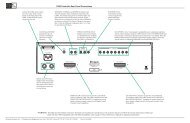
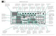
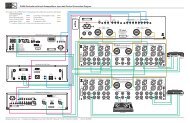
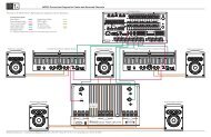
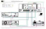
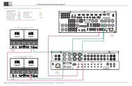
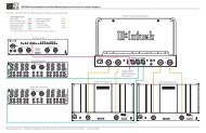
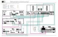
General Information and Connector InformationGeneral Information1. For additional connection information, refer to theowner’s manual(s) for any component(s) connectedto the <strong>C48</strong> <strong>Audio</strong> <strong>Preamplifier</strong>.2. The Main AC Power going to the <strong>C48</strong> and anyother <strong>McIntosh</strong> Component(s) should not be applieduntil all the system components are connectedtogether. Failure to do so could result in malfunctioningof some or all of the system’s normal operations.When the <strong>C48</strong> and other <strong>McIntosh</strong> Componentsare in their Standby Power Off Mode, theMicroprocessor’s Circuitry inside each componentis active and communication is occurring betweenthem.3. Balanced and Unbalanced Inputs and Outputs canbe mixed. For example, you may connect signalsources to Unbalanced Inputs and send signalsfrom the Balanced Outputs. You can also use Balancedand Unbalanced Outputs simultaneously,connected to different Power Amplifiers.4. The <strong>C48</strong> internal Digital to Analog ConverterCircuitry is designed to decode 2-channel PCM(Pulse Code Modulation) Digital Signal present atthe Coaxial and Optical Digital <strong>Audio</strong> Inputs. OtherDigital <strong>Audio</strong> Signal Format Types will cause the<strong>Audio</strong> Outputs of the <strong>C48</strong> to be muted and the FrontPanel Information Display will indicate an errormessage.5. The Remote Control Supplied with the <strong>C48</strong> IntegratedAmplifier is capable of operating othercomponents. For additional information go to www.mcintoshlabs.com.6. When discarding the unit, comply withlocal rules or regulations. Batteries shouldnever be thrown away or incinerated butdisposed of in accordance with the localregulations concerning battery disposal.7. For additional information on the <strong>C48</strong> and other<strong>McIntosh</strong> Products please visit the <strong>McIntosh</strong> WebSite at www.mcintoshlabs.com.Connector and Cable InformationXLR ConnectorsBelow is the Pin configuration for the XLR BalancedInput and Output Connectors on the <strong>C48</strong>. Refer to thediagrams for connections:PIN 1: Shield/GroundPIN 2: + OutputPIN 3: - OutputPIN 2 PIN 1PIN 3PIN 1 PIN 2PIN 3Power Control and Trigger ConnectorsThe <strong>C48</strong> Power Control Out, Trigger and Pass-ThruOutput Jacks send Power On/ Output 1&2, Trig 1&2and Pass-ThruOff Signals (+12 volt/0 volt)when connected to otherPower<strong>McIntosh</strong> Components. An Controladditional connection is forMeterIlluminationcontrolling the illumination ofControlthe Power Output Meters onGround<strong>McIntosh</strong> Power Amplifiers. A1/8 inch stereo mini phone plug is used for connectionto the Power Control, Trigger and Pass-Thru Outputson the <strong>C48</strong>.Note: The Power Control, Trigger, Pass-Thru and DataConnecting Cable is available from the <strong>McIntosh</strong>Parts Department:Power Control, Trigger, Pass-Thru and DataCable Part No. 170-202Six foot, shielded 2 conductor, with 1/8 inch stereomini phone plugs on each end.Data Port ConnectorsThe <strong>C48</strong> Data Out Ports send Remote Control Signalsto Source Components. A 1/8inch stereo mini phone plug isused for connection.DataSignalN/CDataGround4


![Product Brochure [pdf] - Audio Classics](https://img.yumpu.com/43032582/1/190x245/product-brochure-pdf-audio-classics.jpg?quality=85)