McIntosh MC303 Three Channel Power Amplifier ... - TransTec
McIntosh MC303 Three Channel Power Amplifier ... - TransTec
McIntosh MC303 Three Channel Power Amplifier ... - TransTec

Create successful ePaper yourself
Turn your PDF publications into a flip-book with our unique Google optimized e-Paper software.
<strong>Power</strong> <strong>Amplifier</strong><strong>MC303</strong>Owner’s Manual<strong>McIntosh</strong> Laboratory, Inc. 2 Chambers Street Binghamton, New York 13903-2699 Phone: 607-723-3512 www.mcintoshlabs.com
Connector Information, Introduction and Performance FeaturesGeneral Information, con’t6. When discarding the unit, comply with local rulesor regulations. Batteries should never be thrownaway or incinerated but disposed of in accordancewith the local regulations concerning battery disposal.7. For additional information on the <strong>MC303</strong> and other<strong>McIntosh</strong> Products please vist the <strong>McIntosh</strong> WebSite at www.mcintoshlabs.com.8. When the <strong>MC303</strong> is operated in the USA or Canada and themain fuse, located on the rear panel, is in need of replacementuse only the following part:Bussman ABC-15-R or Littlefuse 314-015PConnector and Cable InformationXLR ConnectorsBelow is the Pin configuration for the XLR Balanced InputConnectors on the <strong>MC303</strong>. Refer to the diagram for connection:PIN 1: Shield/GroundPIN 2: + OutputPIN 3: - Output<strong>Power</strong> Control ConnectorThe <strong>MC303</strong>’s <strong>Power</strong> Control Inputs receive On/Off signalsof +5 volts. An additional connectionis for controlling the illumination of <strong>Power</strong>Controlthe <strong>MC303</strong> <strong>Power</strong> Output Meters.MeterThe 1/8 inch stereo mini phone plug Illuminationconnects to a <strong>McIntosh</strong> A/V Control ControlGroundCenter <strong>Power</strong> Control Output.Note: The <strong>Power</strong> Control Connecting Cable is available fromthe <strong>McIntosh</strong> Parts Department:Data and <strong>Power</strong> Control Cable Part No. 170-202Six foot, shielded 2 conductor, with 1/8 inch stereo miniphone plugs on each end.IntroductionNow you can take advantage of traditional <strong>McIntosh</strong>standards of excellence in the <strong>MC303</strong> <strong>Power</strong> <strong>Amplifier</strong>.The 300 watt high current output per channel will driveany high quality loudspeaker system to its ultimate performance.The <strong>MC303</strong> reproduction is sonically transparentand absolutely accurate. The <strong>McIntosh</strong> Sound is “TheSound of the Music Itself.”Performance FeaturesPIN 2 PIN 1PIN 3• <strong>Power</strong> OutputThe <strong>MC303</strong> is a <strong>Power</strong> <strong>Amplifier</strong> with a capability of 300watts per channel (all channels driven) into 2, 4 or 8 ohmspeakers with less than 0.005% distortion. The <strong>Power</strong> <strong>Amplifier</strong>circuitry uses Thermal Trak 1 Output Transistors forlower distortion and cool operation.• Balanced and Unbalanced InputsBalanced connections guard against induced noise and allowlong cable runs without compromising sound quality.• <strong>Power</strong> GuardThe patented <strong>McIntosh</strong> <strong>Power</strong> Guard circuit prevents theamplifier from being over driven into clipping, with itsharsh distorted sound that can also damage your valuableloudspeakers.• Sentry Monitor and Thermal Protection<strong>McIntosh</strong> Sentry Monitor power output stage protectioncircuits ensure the <strong>MC303</strong> will have a long and trouble freeoperating life. Built-in Thermal Protection Circuits guardagainst overheating.• Patented Autoformer<strong>McIntosh</strong> designed and manufactured Output Autoformersprovide an ideal match between the amplifier output stagesand speaker loads of 2, 4 and 8 ohms. The Autoformersalso provide perfect DC protection for your valuable loudspeakers.• Special <strong>Power</strong> SupplyA regulated <strong>Power</strong> Supply, a very large <strong>Power</strong> Transformerand Capacitors ensure stable noise free operation eventhough the power line varies.• Illuminated <strong>Power</strong> MeterThe Illuminated <strong>Power</strong> Output Watt Meter on the <strong>MC303</strong>is peak responding, and indicates the power output of theamplifier. The Front Panel Meter Illumination may beswitched Off at any time.• Fiber Optic Solid State Front Panel IlluminationThe even illumination of the Front Panel is accomplishedby the combination of custom designed Fiber Optic LightDiffusers and extra long life Light Emitting Diodes(LEDs).• Glass Front Panel and Super Mirror Chassis FinishThe famous <strong>McIntosh</strong> Illuminated Glass Front Panel andthe Stainless Steel Chassis with Super Mirror Finish ensuresthe pristine beauty of the <strong>MC303</strong> will be retained formany years.1ThermalTrak and ON Semiconductor are trademarks of SemiconductorComponents Industries, LLC4
DimensionsDimensionsThe following dimensions can assist in determining thebest location for your <strong>MC303</strong>. There is additional informationon the next page pertaining to installing the <strong>MC303</strong>into cabinets.17-3/4"45.09cmFront View of the <strong>MC303</strong>10-7/8"27.62cm12-3/8"31.43cm17-3/8"44.15cmRear View of the <strong>MC303</strong>F15AH 125V12-1/4"31.11cm1-5/8"4.12cm19-1/2"49.50cm18"45.72cmSide View of the <strong>MC303</strong>3/16"0.48cm10-1/2"26.70cm1-1/2"3.81cm14"35.60cm1-9/16"3.96cm5
InstallationInstallationThe <strong>MC303</strong> can be placed upright on a table or shelf,standing on its four feet. It also can be custom installed ina piece of furniture or cabinet of your choice. The four feetmay be removed from the bottom of the <strong>MC303</strong> when it iscustom installed as outlined below. The four feet togetherwith the mounting screws should be retained for possiblefuture use if the <strong>MC303</strong> isremoved from the custominstallation and used freestanding. The requiredpanel cutout, ventilationcutout and unit dimensionsare shown.Always provide adequateventilation for your<strong>MC303</strong>. Cool operationensures the longest possibleoperating life for anyelectronic instrument. Donot install the <strong>MC303</strong> directlyabove a heat generatingcomponent such as ahigh powered amplifier. Ifall the components are installedin a single cabinet,a quiet running ventilationfan can be a definiteasset in maintaining allthe system components atthe coolest possible operatingtemperature.A custom cabinet installationshould provide thefollowing minimum spacingdimensions for cooloperation.Allow at least 6 inches(15.24cm) above the top,2 inches (5.08cm) belowthe bottom and 1 inch(2.54cm) on each side ofthe <strong>Power</strong> <strong>Amplifier</strong>, sothat airflow is not obstructed.Allow 19-1/2inches (49.53cm) depthbehind the front panel.Allow 1-5/8 inch (4.12cm)in front of the mountingpanel 1 for clearance. Be<strong>MC303</strong> Front PanelCustom Cabinet Cutout<strong>MC303</strong> Side Viewin Custom Cabinet<strong>MC303</strong> Bottom Viewin Custom CabinetCabinetFrontPanelOpeningfor VentilationSupportShelf21/32"1.67cmNote: Center the cutout Horizontally on the unit.For purposes of clarity, the aboveillustration is not drawn to scale.sure to cut out a ventilation hole in the mounting shelf accordingto the dimensions in the drawing.1When the <strong>MC303</strong> is installed together with other <strong>McIntosh</strong>Components, check clearances on all components beforeproceeding.6"15.24cm17-9/16"44.62cmCutout Opening for Ventilation1"2.54cm14-1/2"36.83cmCutout Openingfor Ventilation14"35.56cm10 -13/16"27.46cmCutout Opening for Custom MountingChassisSpacers15-5/16"38.91cm6
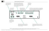
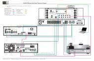
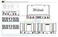
Rear Panel Connections and SwitchUNBALANCED INPUT 3for an audio cable from anA/V Control Center or Preamplifieraudio outputPOWER CONTROL INreceives turn On/Off signalfrom a <strong>McIntosh</strong> componentand the POWER CONTROLOUT sends a turn On/Offsignal to the next <strong>McIntosh</strong>ComponentBALANCED INPUT 2for an audio cable froman A/V Control Centeror Preamplifier audiooutputBALANCED INPUT 1for an audio cable froman A/V Control Centeror Preamplifier audiooutputBALANCED INPUT 3for an audio cable froman A/V Control Centeror Preamplifier audiooutputUNBALANCED INPUT 2for an audio cable from anA/V Control Center or Preamplifieraudio outputUNBALANCED INPUT 1for an audio cable from anA/V Control Center or Preamplifieraudio outputF15AH 125VOUTPUT 3 Connectionsfor 2 ohm, 4 ohm or 8 ohmLoudspeakerOUTPUT 2 Connectionsfor 2 ohm, 4 ohm or 8 ohmLoudspeakerOUTPUT 1 Connectionsfor 2 ohm, 4 ohm or 8 ohmLoudspeakerConnect the <strong>MC303</strong>power cord to a live ACoutlet. Refer to the rearpanel to determine thecorrect voltageMain Fuse holder, refer to information onthe back panel of your <strong>MC303</strong> to determinethe correct fuse size and rating. When usedin the USA and Canada refer to GeneralInformation note number 8 on page 4.7
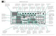
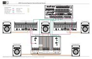
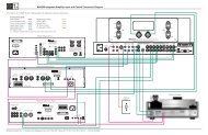
How to Connect for Center and Surround<strong>Channel</strong>sCaution: The supplied AC <strong>Power</strong> Cord should not beconnected to the Rear Panel of the <strong>MC303</strong><strong>Amplifier</strong> until after the Loudspeaker Connectionshave been made. Failure to observe thiscould result in Electric Shock. For additionalinstruction on making Loudspeaker Connectionscontact your <strong>McIntosh</strong> Dealer or <strong>McIntosh</strong>Technical Support.The connection instructions below, together with the<strong>MC303</strong> Connection Diagram located on the separate foldedsheet “Mc1A, is an example of a typical audio/video system.Your system may vary from this, however the actualcomponents would be connected in a similar manner. Foradditional information refer to “Connector and Cable Information”on page 4.1. For Remote <strong>Power</strong> Control, connect a power controlcable from the A/V Control Center or Preamplifier<strong>Power</strong> Control Out to the Right Front <strong>Channel</strong> <strong>Power</strong><strong>Amplifier</strong> <strong>Power</strong> Control In. Connect a second powercontrol cable from the Right Front <strong>Channel</strong> <strong>Power</strong><strong>Amplifier</strong> <strong>Power</strong> <strong>Power</strong> Control Out to the Left Front<strong>Channel</strong> <strong>Power</strong> <strong>Amplifier</strong> <strong>Power</strong> Control In.2. Connect a power control cable from the Left Front<strong>Channel</strong> <strong>Power</strong> <strong>Amplifier</strong> <strong>Power</strong> <strong>Power</strong> Control Out tothe <strong>MC303</strong> POWER CONTROL IN.3. Connect cables from the Balanced Outputs of the A/VControl Center or Preamplifier (Left and Right Front<strong>Channel</strong>s) to the Left and Right Front <strong>Power</strong> <strong>Amplifier</strong>s.Note: An optional hookup is to use the UNBALanced IN-PUTS with unbalanced cables instead of balanced.However, both type of connections for a given Inputshould not be used at the same time.4. Connect cables from the Balanced Outputs of the A/VControl Center or Preamplifier (Center and Surround<strong>Channel</strong>s) to the <strong>MC303</strong> BALANCED INPUTs (1-3).When connecting Loudspeakers to the <strong>MC303</strong> it is veryimportant to use cables of adequate size, so there is little tono power loss in the cables. The size is specified in GaugeNumbers or AWG (American Wire Gauge). The smallerthe Gauge number, the larger the wire size:Loudspeaker Cable Distance vs Wire Gauge GuideLoudspeakerImpedance25 feet(7.62 meters)or less50 feet(15.24 meters)or less100 feet(30.48 meters)or less2 Ohms 12AWG 10AWG 8AWG4 Ohms 14AWG 12AWG 10AWG8 Ohms 16AWG 14AWG 12AWG5. This <strong>McIntosh</strong> <strong>MC303</strong> <strong>Power</strong> <strong>Amplifier</strong> is designed forthe connection of a single Loudspeaker per amplifierchannel, with an impedance of 2 ohms, 4 ohms or 8ohms.Note: The remaining <strong>Amplifier</strong> Loudspeaker Terminalsshould not be connected to another Loudspeaker.6. Prepare the Loudspeaker Hookup Cables that attach tothe <strong>Amplifier</strong> by choosing one of the methods below:Bare wire cable ends:Carefully remove sufficient insulation from the cableends, refer to figures 1, 2 & 3. If the cable is stranded,carefully twistthe strands togetheras tightly as possible.Note: If desired, thetwisted ends canFigure 1 Figure 2 Figure 3be tinned with solder to keep the strands together,or attach spade lug and/or banana connector.Spade lug or prepared wire connection:Insert the spade lug connector or prepared section ofthe cable end into the terminal side access hole, andtighten the terminalcap until the cable isfirmly clamped intothe terminal so thewires cannot slip out. Refer to figures 4, 5 & 6.Banana plug connection:Figure 4 Figure 5 Figure 6Insert the banana plug into the hole at the top of theterminal. Refer to figures A and B.Note: BananaPlugs arefor use inthe UnitedStates andCanadaonly.7. Connect the Loudspeaker hookup cables from a singleLoudspeaker to the output terminals that match theimpedance of OUPUT 1, being careful to observe thecorrect polarities. Output impedance connections of 2ohms, 4 ohms and 8 ohms are provided. If the Loudspeaker’simpedance is in-between the available connections,use the nearest lower impedance connection.Refer to “General Information” Note 5 on page 3 foradditional information.WARNING: Loudspeaker terminals are hazardous liveand present a risk of electric shock.8. In a similar manner, connect a Loudspeaker to OUT-PUT 2 and connect the remaining Loudspeaker toOUTPUT 3.9. Connect the <strong>MC303</strong> <strong>Power</strong> Cord to a live AC outlet.8
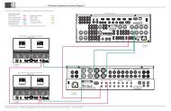
Technical Description<strong>McIntosh</strong> Laboratory, the company who introduced theworld’s first amplifier that could be called “High Fidelity”,has done it again. The <strong>McIntosh</strong> engineering staff has createda power amplifier without compromise, using the mostadvanced <strong>McIntosh</strong> circuit design concepts.A continuous average power output rating of 300 wattsper channel and with an output current of greater than 60amperes per channel, making this one of the most advancedand powerful amplifiers <strong>McIntosh</strong> has ever manufactured.The distortion limits for the <strong>MC303</strong> are no morethan 0.005% at rated power output for all frequencies from20Hz to 20,000Hz. Typical performance at mid frequenciesis less than 0.0002%. The true distortion readings on the<strong>MC303</strong> are so low, it takes special measuring techniquesto make accurate readings. The <strong>MC303</strong> can deliver thebest possible performance from any type of high qualityloudspeaker system.Creating an amplifier with this level of performance didnot come easily. Many months of design, testing and measuringwere required. Extensive controlled listening tests,the ultimate form of measuring, were made before the finaldesign was accepted.Inside Bottom View of the <strong>MC303</strong>12
16Top View of the <strong>MC303</strong>
SpecificationsSpecifications<strong>Power</strong> OutputMinimum sine wave continuous average power output perchannel, all channels operating:300 watts into a 2 ohm, 4 ohm or 8 ohm loadOutput Load Impedance2, 4 or 8 ohmsRated <strong>Power</strong> Band20Hz to 20,000HzTotal Harmonic Distortion0.005% maximum harmonic distortion at any power levelfrom 250 milliwatts to rated power, 20Hz to 20,000HzDynamic Headroom1.8dBFrequency Response+0, -0.25dB from 20Hz to 20,000Hz+0, -3dB from 10Hz to 100,000HzInput Sensitivity (for rated output)1.7 Volt Unbalanced3.4 Volt Balanced<strong>Power</strong> Requirements100 Volts, 50/60Hz at 12 Amps110 Volts, 50/60Hz at 11 Amps120 Volts, 50/60Hz at 10 Amps220 Volts, 50/60Hz at 6 Amps230 Volts, 50/60Hz at 6 Amps240 Volts, 50/60Hz at 6 AmpsStandby: Less than 1 wattNote: Refer to the rear panel of the <strong>MC303</strong> for the correctvoltage.Overall DimensionsWidth is 17-3/4 inches (45.09cm)Height is 12-3/8 inches (31.43cm) including feetDepth is 22 inches (55.88cm) including the Front Panel andCablesWeight155 pounds (70.3 kg) net, 180 pounds (81.6 kg) in shippingcartonShipping Carton DimensionsWidth is 31 inches (78.74cm)Depth is 28 inches (71.12cm)Height is 17-1/4 inches (43.82cm)Signal To Noise Ratio (A-Weighted)112dB below rated outputIntermodulation Distortion0.005% maximum, if the instantaneous peak power outputdoes not exceed twice the rated power output for any combinationof frequencies from 20Hz to 20,000Hz.Wide Band Damping FactorGreater than 40Input Impedance10,000 ohms<strong>Power</strong> GuardLess than 2% THD with up to 14dB overdrive at 1,000Hz<strong>Power</strong> Control Input5VDC - 12VDC<strong>Power</strong> Control Output12VDC, 25mA maximum, delay 0.2 seconds18
Packing InstructionsPacking InstructionsIn the event it is necessary to repack the equipment forshipment, the equipment must be packed exactly as shownbelow. It is very important that the four feet are attached tothe bottom of the equipment. This will ensure the properequipment location on the bottom foam pad. Failure to dothis will result in shipping damage.Use the original shipping carton and interior parts onlyif they are all in good serviceable condition. If a shippingcarton or any of the interior part(s) are needed, please callor write Customer Service Department of <strong>McIntosh</strong> Laboratory.Please see the Part List for the correct part numbers.Quantity Part Number Description1 034105 Shipping carton top1 034104 Shipping carton bottom2 034439 Foam Pad (top and bottom)3 034441 Foam Ring4 018445 Feet19
<strong>McIntosh</strong> Laboratory, Inc.2 Chambers StreetBinghamton, NY 13903www.mcintoshlabs.comThe continuous improvement of its products is thepolicy of <strong>McIntosh</strong> Laboratory Incorporated whoreserve the right to improve design without notice.Printed in the U.S.A.<strong>McIntosh</strong> Part No. 04109800


![Product Brochure [pdf] - Audio Classics](https://img.yumpu.com/43032582/1/190x245/product-brochure-pdf-audio-classics.jpg?quality=85)