Design and Development of 60 GHz Millimeter-wave Passive ...
Design and Development of 60 GHz Millimeter-wave Passive ...
Design and Development of 60 GHz Millimeter-wave Passive ...

You also want an ePaper? Increase the reach of your titles
YUMPU automatically turns print PDFs into web optimized ePapers that Google loves.
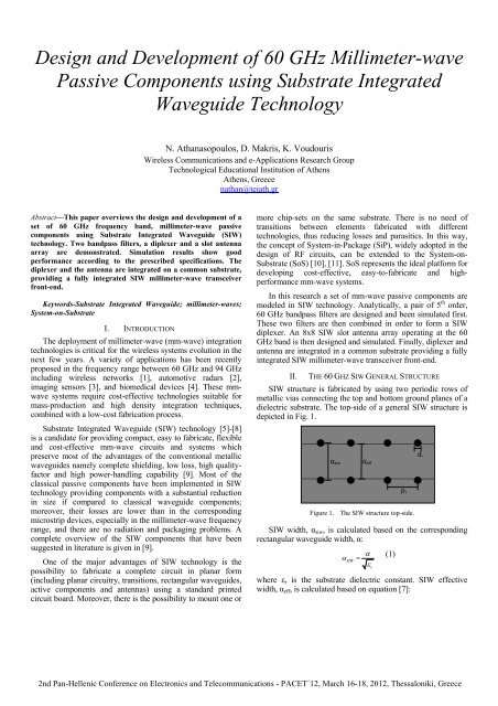
<strong>Design</strong> <strong>and</strong> <strong>Development</strong> <strong>of</strong> <strong>60</strong> <strong>GHz</strong> <strong>Millimeter</strong>-<strong>wave</strong><strong>Passive</strong> Components using Substrate IntegratedWaveguide TechnologyN. Athanasopoulos, D. Makris, K. VoudourisWireless Communications <strong>and</strong> e-Applications Research GroupTechnological Educational Institution <strong>of</strong> AthensAthens, Greecenathan@teiath.grAbstract—This paper overviews the design <strong>and</strong> development <strong>of</strong> aset <strong>of</strong> <strong>60</strong> <strong>GHz</strong> frequency b<strong>and</strong>, millimeter-<strong>wave</strong> passivecomponents using Substrate Integrated Waveguide (SIW)technology. Two b<strong>and</strong>pass filters, a diplexer <strong>and</strong> a slot antennaarray are demonstrated. Simulation results show goodperformance according to the prescribed specifications. Thediplexer <strong>and</strong> the antenna are integrated on a common substrate,providing a fully integrated SIW millimeter-<strong>wave</strong> transceiverfront-end.Keywords-Substrate Integrated Waveguide; millimeter-<strong>wave</strong>s;System-on-SubstrateI. INTRODUCTIONThe deployment <strong>of</strong> millimeter-<strong>wave</strong> (mm-<strong>wave</strong>) integrationtechnologies is critical for the wireless systems evolution in thenext few years. A variety <strong>of</strong> applications has been recentlyproposed in the frequency range between <strong>60</strong> <strong>GHz</strong> <strong>and</strong> 94 <strong>GHz</strong>including wireless networks [1], automotive radars [2],imaging sensors [3], <strong>and</strong> biomedical devices [4]. These mm<strong>wave</strong>systems require cost-effective technologies suitable formass-production <strong>and</strong> high density integration techniques,combined with a low-cost fabrication process.Substrate Integrated Waveguide (SIW) technology [5]-[8]is a c<strong>and</strong>idate for providing compact, easy to fabricate, flexible<strong>and</strong> cost-effective mm-<strong>wave</strong> circuits <strong>and</strong> systems whichpreserve most <strong>of</strong> the advantages <strong>of</strong> the conventional metallic<strong>wave</strong>guides namely complete shielding, low loss, high qualityfactor<strong>and</strong> high power-h<strong>and</strong>ling capability [9]. Most <strong>of</strong> theclassical passive components have been implemented in SIWtechnology providing components with a substantial reductionin size if compared to classical <strong>wave</strong>guide components;moreover, their losses are lower than in the correspondingmicrostrip devices, especially in the millimeter-<strong>wave</strong> frequencyrange, <strong>and</strong> there are no radiation <strong>and</strong> packaging problems. Acomplete overview <strong>of</strong> the SIW components that have beensuggested in literature is given in [9].One <strong>of</strong> the major advantages <strong>of</strong> SIW technology is thepossibility to fabricate a complete circuit in planar form(including planar circuitry, transitions, rectangular <strong>wave</strong>guides,active components <strong>and</strong> antennas) using a st<strong>and</strong>ard printedcircuit board. Moreover, there is the possibility to mount one ormore chip-sets on the same substrate. There is no need <strong>of</strong>transitions between elements fabricated with differenttechnologies, thus reducing losses <strong>and</strong> parasitics. In this way,the concept <strong>of</strong> System-in-Package (SiP), widely adopted in thedesign <strong>of</strong> RF circuits, can be extended to the System-on-Substrate (SoS) [10], [11]. SoS represents the ideal platform fordeveloping cost-effective, easy-to-fabricate <strong>and</strong> highperformancemm-<strong>wave</strong> systems.In this research a set <strong>of</strong> mm-<strong>wave</strong> passive components aremodeled in SIW technology. Analytically, a pair <strong>of</strong> 5 th order,<strong>60</strong> <strong>GHz</strong> b<strong>and</strong>pass filters are designed <strong>and</strong> been simulated first.These two filters are then combined in order to form a SIWdiplexer. An 8x8 SIW slot antenna array operating at the <strong>60</strong><strong>GHz</strong> b<strong>and</strong> is then designed <strong>and</strong> simulated. Finally, diplexer <strong>and</strong>antenna are integrated in a common substrate providing a fullyintegrated SIW millimeter-<strong>wave</strong> transceiver front-end.II. THE <strong>60</strong> GHZ SIW GENERAL STRUCTURESIW structure is fabricated by using two periodic rows <strong>of</strong>metallic vias connecting the top <strong>and</strong> bottom ground planes <strong>of</strong> adielectric substrate. The top-side <strong>of</strong> a general SIW structure isdepicted in Fig. 1.α siwFigure 1. The SIW structure top-side.SIW width, α siw , is calculated based on the correspondingrectangular <strong>wave</strong>guide width, α:αSIWα effα=εwhere ε r is the substrate dielectric constant. SIW effectivewidth, α eff , is calculated based on equation [7]:r(1)p vd v
2 2dvdvαeff = αsiw−1.08⋅ + 0.1⋅ (2)pvαsiwVia diameter d v <strong>and</strong> pitch via p v should be appropriately setin order to ensure that there is no radiation leakage betweenmetallic vias due to diffraction. In [12], the following designrules are given in order to avoid such effects:<strong>and</strong>d vλg< (3)5p ≤ 2d(4)vIn this research, pitch via <strong>and</strong> via diameter are set equal top v =0.35 mm <strong>and</strong> d v =0.2 mm respectively. Dielectric substrateRogers RT/duroid 5880 (ε r =2.2, dielectric thickness h=0.508mm) is considered. The <strong>60</strong> <strong>GHz</strong> frequency b<strong>and</strong> rectangular<strong>wave</strong>guide (WR-15) width is α=3.759 mm. Applying (1), SIWwidth is calculated, while, based on (2) SIW effective width isalso calculated. All SIW basic design parameters for the <strong>60</strong><strong>GHz</strong> frequency b<strong>and</strong> are summarized in Table I.vFigure 3. Simulation results for the 59.8 <strong>GHz</strong> SIW b<strong>and</strong>pass filter.TABLE I. SIW DESIGN PARAMETERS AT <strong>60</strong> GHZDielectric Substrate: RT/duroid 5880Parameter(ε r =2.2, h=0.508 mm)Symbol Value UnitPitch Via p v 0.35 mmVia Diameter d v 0.2 mmSIW Width α siw 2.8 mmSIW Effective Width α eff 2.678 mmIII. <strong>60</strong> GHZ SIW BANDPASS FILTERSThe design methodology <strong>of</strong> the two SIW b<strong>and</strong>pass filtershas been analytically presented by the authors in [13]. Centerfrequencies for the two filters are 59.8 <strong>GHz</strong> <strong>and</strong> 62.2 <strong>GHz</strong>respectively. B<strong>and</strong>width is 1 <strong>GHz</strong>, <strong>and</strong> filter order is 5. Basedon these specifications, authors in [13] compute the designparameters <strong>of</strong> both filters. 50 Ohm SIW-microstrip transitionsare suitably designed in order to enable TE 10 modepropagation. Fig. 2 depicts the HFSS SIW b<strong>and</strong>pass filtermodel.Figure 4. Simulation results for the 62.2 <strong>GHz</strong> SIW b<strong>and</strong>pass filter.IV. <strong>60</strong> GHZ SIW PLANAR DIPLEXERAuthors in [14] presented the <strong>60</strong> <strong>GHz</strong> planar diplexer inSIW technology which is developed by the integration <strong>of</strong> thetwo 5 th order SIW b<strong>and</strong>pass filters been presented in theprevious section. Integration is achieved through a SIW T-junction which is designed so as TE 10 mode to be propagated,<strong>and</strong> incident electromagnetic <strong>wave</strong>s at channel filters’ ports tobe equal-amplitude <strong>and</strong> in-phase. 50 Ohm SIW-microstriptransitions are also designed for all diplexer ports. The SIWplanar diplexer HFSS design is presented in Fig. 5.Figure 2. HFSS model for the 5 th order SIW b<strong>and</strong>pass filter.Fig. 3 presents the HFFS simulation results for 59.8 <strong>GHz</strong>b<strong>and</strong>pass filter. Insertion loss is about 2 dB while return lossvaries below 20 dB for the 1 <strong>GHz</strong> pass b<strong>and</strong>. Filter rejection at62.2 <strong>GHz</strong> is 66 dB. Fig. 4 shows the HFFS simulation resultsfor 62.2 <strong>GHz</strong> b<strong>and</strong>pass filter. Insertion loss is 1.5 dB whilereturn loss varies below 20 dB for the 1 <strong>GHz</strong> pass b<strong>and</strong>. Filterrejection at 59.8 <strong>GHz</strong> is 90 dB.Figure 5. The <strong>60</strong> <strong>GHz</strong> SIW planar diplexer HFSS model.Fig. 7 shows the common port (Port 1) return loss, thetransmission responses as well as the channel-to-channelisolation, whereas Fig. 8 the channel filters’ return losses.According to the simulation the insertion losses are about 3.5dB for receive <strong>and</strong> transmit 1 <strong>GHz</strong> pass b<strong>and</strong>s. Receive <strong>and</strong>transmit out-<strong>of</strong>-b<strong>and</strong> rejection is 52 dB at transmit <strong>and</strong> receive
filter center frequencies respectively while channel-to channelisolation varies below <strong>60</strong> dB. Finally, common port return lossas well as receive <strong>and</strong> transmit return loss vary below 12.5 dB.TABLE II.ParameterSlot Length8X8 SIW SLOT ANTENNA DESIGN PARAMETERSSymbolSLTheoretical OptimizedValue Value1.97 1.80UnitmmSlot Spacing SS 2.17 2.17 mmSlot to Top ST 3.25 3.00mmSlot Width SW 0.18 0.20 mmSlot Offset SO 0.15 - 0.25 0.18mmFigure 6. HFSS simulated transmission responses, isolation <strong>and</strong> commonport return loss for the diplexer.Figure 8. The <strong>60</strong> <strong>GHz</strong> 8x8 SIW slot antenna array HFSS model.Figure 7. HFSS simulated return losses for diplexer receive <strong>and</strong> transmitchannel filters.V. <strong>60</strong> GHZ SIW SLOT ANTENNA ARRAYAn 8x8 SIW slot antenna array was designed based onanalysis suggested in [15]. Feeding network at the input <strong>of</strong> theantenna divides the signal to 8 in-phase, equal amplitudesignals <strong>and</strong> a 50 Ohm SIW-microstrip transition is usedlikewise. The 8x8 SIW slot antenna array HFSS model ispresented in Fig. 8.Slot Spacing (SS) is equal to the half <strong>of</strong> guided <strong>wave</strong>length λ g<strong>and</strong> Slot to Top (ST) is equal to the three-quarter <strong>of</strong> λ g shortcircuittermination. Slot Width (SW) varies between one tenth<strong>and</strong> one twentieth <strong>of</strong> SL, determining the desired b<strong>and</strong>width.The position <strong>of</strong> each slot relative to the centerline <strong>of</strong> each array(SO) is analytically described in [16]. Finally, Slot Length (SL)is computed based upon [17]. In Table II, both theoretical <strong>and</strong>optimized using HFSS design parameters are summarized forthe 8x8 SIW slot antenna array.Fig. 9 shows the antenna return loss simulation results.According to that, S 11 varies below -10 dB in the range from58.6 <strong>GHz</strong> to 63 <strong>GHz</strong> covering the pass b<strong>and</strong>s <strong>of</strong> the diplexerchannel filters been presented in previous section. Fig. 10shows radiation pattern simulation results. Beamwidth is 15.5 0<strong>and</strong> 10.7 0 in azimuth <strong>and</strong> elevation planes respectively. Thegain is 21.64 dB.Figure 9. HFSS simulated return loss at the input <strong>of</strong> the antenna.Figure 10. The HFSS azimuth <strong>and</strong> elevation radiation patterns.