Understanding Fan Curves - Clarage
Understanding Fan Curves - Clarage
Understanding Fan Curves - Clarage
- No tags were found...

You also want an ePaper? Increase the reach of your titles
YUMPU automatically turns print PDFs into web optimized ePapers that Google loves.
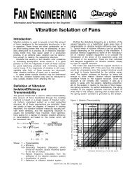
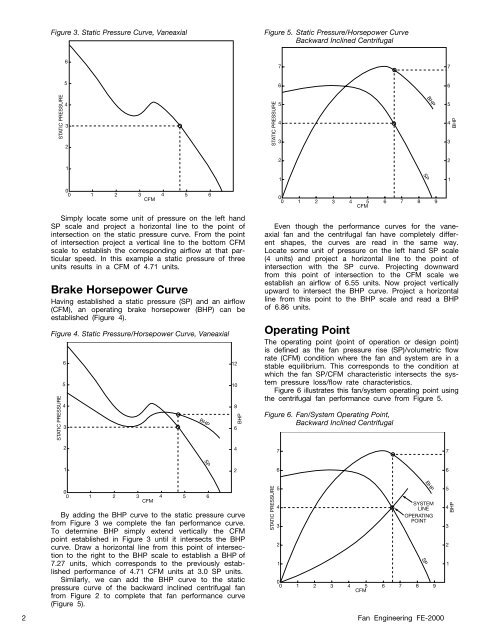
SPFigure 3. Static Pressure Curve, VaneaxialFigure 5. Static Pressure/Horsepower CurveBackward Inclined Centrifugal677566STATIC PRESSURE432STATIC PRESSURE543BHP543BHP1221SP10 0 1 2 3 4 5 6CFMSimply locate some unit of pressure on the left handSP scale and project a horizontal line to the point ofintersection on the static pressure curve. From the pointof intersection project a vertical line to the bottom CFMscale to establish the corresponding airflow at that particularspeed. In this example a static pressure of threeunits results in a CFM of 4.71 units.Brake Horsepower CurveHaving established a static pressure (SP) and an airflow(CFM), an operating brake horsepower (BHP) can beestablished (Figure 4).Figure 4. Static Pressure/Horsepower Curve, VaneaxialSTATIC PRESSURE6543BHP12108BHP60 0 1 2 3 4 5 6CFMEven though the performance curves for the vaneaxialfan and the centrifugal fan have completely differentshapes, the curves are read in the same way.Locate some unit of pressure on the left hand SP scale(4 units) and project a horizontal line to the point ofintersection with the SP curve. Projecting downwardfrom this point of intersection to the CFM scale weestablish an airflow of 6.55 units. Now project verticallyupward to intersect the BHP curve. Project a horizontalline from this point to the BHP scale and read a BHPof 6.86 units.Operating PointThe operating point (point of operation or design point)is defined as the fan pressure rise (SP)/volumetric flowrate (CFM) condition where the fan and system are in astable equilibrium. This corresponds to the condition atwhich the fan SP/CFM characteristic intersects the systempressure loss/flow rate characteristics.Figure 6 illustrates this fan/system operating point usingthe centrifugal fan performance curve from Figure 5.Figure 6. <strong>Fan</strong>/System Operating Point,Backward Inclined Centrifugal7 8 92477126600 1 2 3 4 5 6CFMBy adding the BHP curve to the static pressure curvefrom Figure 3 we complete the fan performance curve.To determine BHP simply extend vertically the CFMpoint established in Figure 3 until it intersects the BHPcurve. Draw a horizontal line from this point of intersectionto the right to the BHP scale to establish a BHP of7.27 units, which corresponds to the previously establishedperformance of 4.71 CFM units at 3.0 SP units.Similarly, we can add the BHP curve to the staticpressure curve of the backward inclined centrifugal fanfrom Figure 2 to complete that fan performance curve(Figure 5).2 <strong>Fan</strong> Engineering FE-2000STATIC PRESSURE543210 0 1 2 3 4 5 6CFMBHPSYSTEMLINEOPERATINGPOINTSP7 8 95432BHP1