Download User/Installation Manual - Airconwarehouse.com
Download User/Installation Manual - Airconwarehouse.com
Download User/Installation Manual - Airconwarehouse.com

Create successful ePaper yourself
Turn your PDF publications into a flip-book with our unique Google optimized e-Paper software.
1. Safety NoticeContent2. <strong>Installation</strong> Drawing3. Technical Data Table4. Electric Drawing5. <strong>Installation</strong> and Debugging6. Controller Operation/Instruction7. Maintenance and Troubleshooting8. Important NotesPage 1 of 19
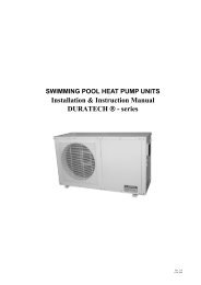
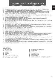
1. Safety noticeFor safety, please follow the instructions below:! All units must be installed by qualified personnel.! The AC input must be connected to a suitable ground leakage device and thefuse rated for 1.5-2 times max current.! The AC input wire if damaged must be changed by qualified personnel only.! The controller must be fitted in a dry location where it can easily beobserved and operated.! The controller is set to its factory default settings and does not need to bereset; please refer to the controller operation/instructions section.! Water temperature setting:Environment temp:≥18℃Environment temp:≤18℃Water temp:45℃~50℃Water temp:50℃~55℃! The water pump used with the unit must have approved certification! At the above temperatures, hot water for domestic use should be mixed withcold water to avoid burns.! Be sure to install a water flow switch in the hot water circulation system anda Y-type filter (with 60meshes) on the water inlet side to provide a stableworking condition for the heat pump. Water flow from heat pump inlet andoutlet side should not be lower than 1.6t/h. The water pump flow anddelivery rate depend on the installation site.! Turn power off if the heat pump is not being used for a long time and drainit. For full instructions refer to the <strong>Installation</strong> and Debugging section.! The manufacturer cannot be held responsible for damage caused byimproper operation.Page 2 of 19
2. <strong>Installation</strong> drawingPage 3 of 19
4. Electric DrawingRS-62P5A/T1RS-42P5ACY/GBNY/GCompressorOutdoor Motor-MC-MF SolarSwater pumpBK WErrorM Capacitance M signle-C11~-C2 1~M(R)BEBEBE-YVWFour ValveBEBERWRBNBEbk2<strong>com</strong>p2o-fanvalvepumpheatN.O.N5 5COMAP4 ControlPanelLine-Controlbk1 Steep1Steep2<strong>com</strong>p1ONtrans in1 2 3 4sw2 2trans outTransformerTECT WT LWCN11CN9CN10CN7 CN8CN6CN5CN2 CN3 CN4CN1HWLV1LV2Phase protection SwitchWater flow SwitchHDO SignalNo. 1 low pressure SwitchNo. 2 low pressure SwitchRelease temp sensor1Coil Temp Sensor1Intake temp sensor1Outdoor temp sensorOutlet water tempHot water temp sensorFree Switch inSolar Temp Sensorθθθθθθθ-XTY/GL N PUMP HEAT N1BNBE220V-240V/50HzPOWER★HEATERM1~PUMPY/GNote1:★HEATER---installed according to user's needs,here shows AC signalonly,it cannot be connected to assistant electric heater directly!Note2:protecting switch connection can be connected according touser's needs:or leave it unusedNote3:"CN1~CN3、<strong>com</strong>p2、steep2、LV2"are availabli for double systemsafter settingToggle Switch:SW1--ON(Winding direction)SW2--ON(HDO Signal)SW3--ON(Solar)SW4--OFF(Air Source)SW4--ON(Water Source)Y/G-Yellow/GreenBN-BrownBE-BlueOR-OrangeBK-BlackW-White R-RedPage 5 of 19
RS-82P5A/T1AC ContactorBN-KMCompressorOutdoor Motor-MC-MF SolarSwater pumpBK WErrorC M Capacitance M signle-C15 51~-C2 1~Y/GBE WM(R)bk2A2BEA1BEBE-YVFour ValveBEBERWRORBNBE<strong>com</strong>p2o-fanvalvepumpheatN.O.NCOMAP4 ControlPanelLine-Controlbk1 Steep1Steep2<strong>com</strong>p1ONtrans in1 2 3 4sw2 2trans outTECT WT LWHWLV1LV2CN11CN9CN10CN7 CN8CN6CN5CN2 CN3 CN4CN1Phase protection SwitchWater flow SwitchHDO SignalNo. 1 low pressure SwitchNo. 2 low pressure SwitchRelease temp sensor1Coil Temp Sensor1Intake temp sensor1Outdoor temp sensorOutlet water tempHot water temp sensorFree Switch inSolar Temp SensorθθθθθθθY/GTransformer-XTL N PUMP HEAT N1Y/G BN BE220V-240V/50HzPOWER★HEATERM1~PUMPY/GNote1:★HEATER---installed according to user's needs,here shows AC signalonly,it cannot be connected to assistant electric heater directly!Note2:protecting switch connection can be connected according touser's needs:or leave it unusedNote3:"CN1~CN3、<strong>com</strong>p2、steep2、LV2"are availabli for double systemsafter settingToggle Switch:SW1--ON(Winding direction)SW2--ON(HDO Signal)SW3--ON(Solar)SW4--OFF(Air Source)SW4--ON(Water Source)Y/G-Yellow/GreenBN-BrownBE-BlueOR-OrangeBK-BlackW-White R-RedPage 6 of 19
5. <strong>Installation</strong> and Debugging5.1 Operating conditions:The heat pump operates normally under the following conditions:Ambient Temperature: -8℃-43℃Relative Humidity: ≤95%Power Supply: 220V/-/50Hz Any conductive material, explosive gas, or corrosive gas that woulddamage the metal or isolation material of heat pump should not be in thevicinity. The unit is re<strong>com</strong>mended to be installed outdoors or in the basement.5.2 Transportation and <strong>Installation</strong>: During transportation the unit must be right side up and should not beinclined more than 30° degrees from the vertical.The unit must be positioned with clearance in the front and on both sides: 1mfrom the front and 2m from both sides. The unit should be firmly installed withinan inclination ≤2/1000. The 220V/50Hz power supply should not be too far away from the unit toavoid high pressure drop when <strong>com</strong>pressor starts. It is suggested to use2.5~16mm 2 four-core cable without joints and power switch with residualcircuit breaker. Wiring according to the electric drawing. Be sure the unit iswell grounded (a 5meter ground line is supplied with the unit).Inlet and outlet pipe connections should be checked to avoid leaks and anyexcessive pressure. A valve, filter and pressure gauge should be installed at theinlet side to control the input water pressure and flow and clear the water before itgoes into the circulation system. Refer to the installation drawing (page 3) forinstallation details. Pressure of the circulation pipes inside the heat pump should bewithin the limit of 0.6MPa.The heat pump can be connected to a solar system if needed:Clear the water inside the system if the unit is to be stopped for a long time toavoid frozen and damage of heat exchanger and water pump in cold winter.Instruction of drainage:a) Remove the four screws at the bottom of the back plate and the drainagePage 7 of 19
pan.b) Turn the knob of the outfall under the condenser to a 90°round (forward orreverse) and the water inside the system will flow out.c) Turn the knob to the original position after the water is clean.d) Replace the back plate and refit it to the drainage pan.★Note on re-operation of the unit: Filling water tank before electrified, thenpower on the unit; make sure clearance of water pump (see Debugging process a).5.3 Debugging:Each unit has been tested before leaving the factory. <strong>User</strong>s do not need tomake any changes. Ensure correct connect of the unit to the external watercirculation system. Then connect the power supply and check if there is anydamage or leak. After that the unit is ready to be switched on.The debugging processes are:a) Fill the water tank to a demand height, open all the valves and empty thewhole waterway system, be sure there is no air in the pipes, or it will causemalfunction of water pump and the unit.b) Be sure all wire connections are correct according to the electric drawing.c) Set the water temperature referring to the Controller Instruction section.d) Press the “on/off” button for 3 seconds, fan motor and water pump willstart in 3 minutes; <strong>com</strong>pressor starts 1 minute later and begins to heat the water. Ifan electric assistant is installed, the electronic control system may activate theassistant heater when the ambient temperature is sensed to be 2degree C. No userintervention is required.e) The system will automatically check the release temperature, coiltemperature, intake temperature, water temperature, as well as water outlettemperature while the unit is operating. If an error occurs, the error code will bedisplayed on the control panel.f) Compressor stops running when the water reaches its set temperature; fanmotor and water pump stop 1 minute later.g) Defrosting will be done automatically when the ambient temperature is toolow to prevent ice on surface of the evaporator. The defrost functions depending onthe coil temperature.Page 8 of 19
6. Controller Operation/Instruction6.1 Functions of the control buttons⑹⑺⑸⑷FCLKTMODE⑻Function Area⑴---on/off⑵---mode⑶---time⑷---function⑶ ⑵ ⑴⑸---temp up⑹---temp down⑺---clock⑻---manual defrost----------- On/Off button (water temp and clock display when heat pump is off)---------- To choose the parameter setting items and to adjust the clock---------- Press for 3 seconds to enter parameter setting-------- Adjust temp and set the parameter, press for 3 seconds to enter the checkingmode---------- Enter clock setting----------- Set the on/off time------------ <strong>Manual</strong>ly defrosting button, press for 3 seconds to enter defrostingInstruction for the time limit: after being electrified for more than 180 days(parameter P6), the unit will stop working immediately and “000” will flash on thecontroller, please press buttonto type in the code, and then press buttonPage 9 of 19
to confirm andto choose the position. Correct code will delete the time limitand the heat pump will start to work again; if entering wrong code for 3 times, theunit will be locked and stop working.6.1.1 Clock settingPress , “hour” flashes, press again to adjust the hour, pressfor 3 seconds and it will step forward quickly; pressto enter “minute”flashing state while “minute” flashes and pressto adjust the minute.6.1.2 Parameter settingWhen the unit is power off, pressover 3 seconds to enter the parametersetting, pressto choose the parameter needed to be adjusted, and then pressto adjust.Serial Function Unit Setting range DefaultP1 Water temp ℃ 30~70 55P2 Time to enter into defrost minute 20~90 40P3 Qty of <strong>com</strong>pressor piece 1~2 1P4Memory function afterloosing electricity00: no memory 01: with memory 01P5 Phase protection 00: no protection 01: with protection 00P6 Max. running day day 1-199 180P7 Time limit 0: no time limit,1: with time limit 0P8 Unit of temperature 0=℃ ,1=℉ 0P9 Qty of heat pump 1~16 1P10 Temperature difference 1~10 4Page 10 of 19
6.1.3 Temperature checking functionWhen the unit is on, press buttons and d1, d2, d3, d4, d5, d6, d7, d8, d9,d10, and d11 will show on the clock display area, and then press or tocheck related temp, which referring to the: intake temp, coil temp, opening ofexpansion valve, release temp, water temp, outdoor temp, water outlet pipe temp,intake temp2, coil temp2, opening of expansion valve2, and release temp2 insystem2. (Note d8, d9, d10, and d11 available on <strong>com</strong>mercial heat pumpRS-280Y5A/T2 only.)In general condition, the controller shows current water temperature.6.1.4 Setting the on/ off timePressonce to enter setting of “on” time, the “Hour” flashes and then pressto adjust the required hour; press, “Minute” flashes on the display, pressto adjust the minute; pressonce more to enter setting of timing “off”: the“hour” flashes and press to adjust the required hour; press , “Minute”flashes and then press to adjust the minute; press one more time and thecirculation of automatically timing on/off will be set. If no press in 10 secondsafter each setting, it will confirm the function by showing “timing on” or “timingoff” or “cycling timing on/off” and the unit will work under controlling of thistiming function. One more press ofand the timer function will be eliminated.Adjusting range: hour: 0-23, minute: 0-59The clock display area will not show the timer but current time; the range of timersetting: 0~23h with the interval of 1hour. The timer can be adjusted under both onPage 11 of 19
and off mode.6.1.5 When heat pump is on, press for 3 seconds and the unit will enter thefunction of manually defrosting, pressagain for 3 seconds to retreat.6.2 Controller display⑷ ⑸⑶⑵⑴HEATTEMP℃TIMELCD Area⑹⑴---Heat display⑵---Temp display⑶---Wind display⑷---Defrost⑸---Electric heater⑹---Time display6.2.1 When heat pump is electrified and ready to be switched onThe controller shows current water temperature and time alternatively.6.2.2 When heat pump is switched onThe controller shows current water temperature, time, as well as the workingmode “HEAT” (the heat pump acts as heater only), working mode of the fan motor,electric assistant, and <strong>com</strong>pressor, etc.On the temperature setting position, it always shows the hot watertemperature except when actually setting the temperature. The current watertemperature will be shown when the unit is powered off.6.2.3 DefrostingPage 12 of 19
The symbolindicates that defrosting is functioning.6.2.4 Electric Assistant Heater:The symbol indicates the electric assistant is working.6.2.5 Error Code Display:When an error occurs, an E:XX appears on the time display area and it willshow with water temperature in alternative.6.3 Protection Function:6.3.1 Release Temperature (<strong>com</strong>pressor overheat protection)When the release temp of <strong>com</strong>pressor is higher than 120℃, <strong>com</strong>pressor, fanmotor, and water pump will be stopped and will not restart automatically;6.3.2 Communication ProtectionIf an error happens to the <strong>com</strong>munication between heat pump and thecontroller and lasts for one minute, then error code E10 will appear and the unitstops running.6.3.3 Water Pump Anti-freezing:To prevent external pipe gets frozen:If the water outlet pipe temperature is sensed to be lower than 7℃, then thewater pump will be activated for 1minute; for an interval of 3minutes, if thistemperature gets higher than 12℃, the water pump will be stopped; if not, thiscirculation keeps going on.6.3.4 Pressure release protection:When the release temperature gets to 105 ℃ , the fan will stop; when thetemperature drops to 95 ℃ , the fan starts again. But the fan cannot stop longer than10minutes; the controller will <strong>com</strong>mand the fan to run for 1minute after it hasstopped for 10minutes, and recycle until the release temperature is lower than 95℃.If the temperature keeps rising during the process of pressure release to 115 ℃ , the<strong>com</strong>pressor will stop and error shows up to stop the heat pump.Page 13 of 19
7. Maintenance and TroubleshootingThe unit is equipped with various safety protection functions for more stableand secure operation. It requires regular check on a number of system <strong>com</strong>ponents.Depending on the environment, the user should check and clean the surface ofevaporator once in a month.Multiple error protection have been set to the unit, correspondent code willshow up when an error happens. Please feedback to the distributor or ask forprofessional personnel’s help.Ordinary errors:Error Cause Diagnostic method andmeasurementCompressor stopsWater not getting warm for along timeNo display on control panelNo producing hot water, fanblowing hot airFan motor not runningPower supply not connected Check power supply wiringand switchesController not switched on Press “ON” to operateController shows error code Check corresponding errorcodeHeat exchanger covered by dust Clean heat exchangerAmbient temperature is too low Ensure the ambient temp iswithin the operating rangeRefrigerant leakingCheck/Fix leakage, refillingR410a refrigerantPower supply not connected Check power supply wiringand switchesBad connection of <strong>com</strong>munication Check if powerline<strong>com</strong>munication line is loosenFour-way valve damaged Have the four-way valvechangedFan motor or capacitor damaged Check if the motor loop orcapacitor is damaged andchange it.Wire loosenEnsure all connections arestable.Page 14 of 19
Error Code:Error code Description of Error Error code Description of ErrorE00 Intake temp sensor error E11 Stop working caused by low pressure2E01 Coil temp sensor error E12 Stop working caused by low pressureE02 Release temp sensor error E13 Solar system temp sensor errorE03 Release temp over heated E14 Water outlet pipe temp sensor erroralarmE04 Intake temp sensor malfunction E15 Electric board <strong>com</strong>munication errorin system2E05 Coil temp sensor malfunction E16 Phase protection errorin system2E06 Release temp sensor E17 Water flow errormalfunction in system2E07 Release temp over heated E18 Low pressure error2alarm in system 2E08 Water temp sensor error E19 Low pressure errorE09Ambient temp sensor errorE10 Controller <strong>com</strong>municationerrorNote: when it says system2 means it only functions in <strong>com</strong>mercial heat pump RS-280Y5A/T2,but not available for King Heater series.Instructions: the controller has a multiple control function, which is for controlling several heatpumps installed in parallel. When the heat pumps are electrified, the controller automaticallysenses the water temperature and if the water temperature sensor is faulty, it will give a sign of<strong>com</strong>munication error and shows E10 on the display. But when the heat pump is running, it willshow E08 as the error of the water temperature sensor error.Instructions for multiple-installation (several heat pumps installed in parallel):1. P9 on the controller shows the quantity of heat pumps in a multiple-installation. Setting rangegoes from 1~16, default to be 1.2. Controller for the major heat pump and subsidiary one works likewise. The water temperaturesensor connects to the major heat pump only. Those without this sensor are determined to besubsidiary unit.3. The subsidiary heat pumps will be sorted in series and keep the same controlling functions asthe major unit.Page 15 of 19
4. The data for each subsidiary heat pump can be checked on the controller by pressing “ ”and then the “clk”. Pressto check each data with a form of “ndxx” (n: number of thesubsidiary unit; xx: number of the data; ndl=intake temperature, nd2=coil temperature,nd3=opening of expansion valve, nd4=release temperature, nd5=running time of the subsidiaryunit, nd6=outdoor temperature, nd7=water outlet temperature, nd12=solar temperature;nd8~nd11 only available for heat pump model RS-280Y5A/T).Press “clk” to retreat the checking mode.5. Communication lose: error code shows as dnXX (xx: number of the subsidiary unit), pleasecheck the connection and fix it.6. Single error for subsidiary unit, showing as: dexx (xx=number for the error, d=number of theerror subsidiary unit).7. The single and double system must be set through controller. The subsidiary unit automaticallychecks out if there is a second system, if not, it will explain it a single system.If connected to the net, please connect end of “a” and “b” to make it functioned.When the heat pump is decided to be a subsidiary unit, it will depend on the position of thetoggle switch to make the sequence of the subsidiary. Please notice as following:Sub. No. 1 Sub. No. 2 Sub. No. 3 Sub. No. 4Sub. No. 5 Sub. No. 6 Sub. No. 7 Sub. No. 8Sub. No. 9 Sub. No. 10 Sub. No. 11 Sub. No. 12Sub. No. 13 Sub. No. 14 Sub. No. 15 Note: blackside refers tothe positionof the toggleswitch.Page 16 of 19
8. Important Notes8.1 After the installation, please add on a flashing shed to prevent rain or snowfrom dripping directly onto the machine. The ambient temperature is relatively lowwith higher humidity in winter, thus the vent side would be easily covered by iceafter some times of accumulation. Therefore, the performance as well as life spanof the unit will be affected without protection of a flashing shed; the worstsituation may lead to bad function of heat pump.Flashing shedHeat pumpRequirement of the flashing shed:It must cover the whole unit, with the size: front of shed 100mm over front of heatpump; back of shed 400mm over back(with net) of heat pump; right side of shed100mm over right side of heat pump; left side of shed 400mm over left side(withnet)of heat pump. The details are specified in the pictures above.Page 17 of 19
8.2 If the heat pump is connected to a pressurized water tank, make sure the tankmeets with the requirement in P1 and P2. Water pump should be Wilo pumpPUN-200E. All the problems happened to heat pump caused by unfixed water tankor water pump should be responsible by the installer.″hot outwater″water temp sensor″outlet fromheat pump″″clod inlet fromtap waterinlet fromheat pumpL pressurized tankPage 18 of 19
″hot outlet″w ater tem psensor″outlet fromheat pump″″cold inle t fromtap waterinlet fromheat pumpL pressurized tankNote: the right to make any change to the designation will be reserved to themanufacturer. Should anything be changed, please refer to the nameplatesticking on the side of the heat pump for correct data.Page 19 of 19