LDTM-Switchgear_12-36kV_E_F13-1.0W.pdf - Driescher • Wegberg
LDTM-Switchgear_12-36kV_E_F13-1.0W.pdf - Driescher • Wegberg
LDTM-Switchgear_12-36kV_E_F13-1.0W.pdf - Driescher • Wegberg

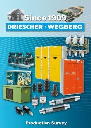
Create successful ePaper yourself
Turn your PDF publications into a flip-book with our unique Google optimized e-Paper software.
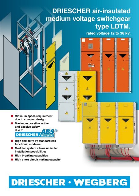
DRIESCHER air-insulatedmedium voltage switchgeartype <strong>LDTM</strong>.rated voltage <strong>12</strong> to 36 kV.■■Minimum space requirementdue to compact design■ ■ Maximum possible activeand passive safetydue to■ ■ High flexibility by standardizedfunctional modules■ ■ Modular system allows unlimitedinstallation possibilities■ ■ High breaking capacities■ ■ High short circuit making capacity
<strong>LDTM</strong>-B: Maximum safety onminimum space.■■Minimum space requirement due to block design■■Arrangement Cable-Cable-Transformer for the use innon-walk in type distribution stations in local mains■■Maximum amount of active and passive safetydue to<strong>LDTM</strong>-B <strong>12</strong> / 630■■High breaking capacities■■High short circuit making capacity■■Clear mechanism assignment due to coloureddesign of the cubiclesIn the lower section two cable switch-disconnectorsare arranged side by side. The fuse switch-disconnectorcombination is located in the upper section.The fuse panel is separated to the busbar which is arrangedin the middle.The connection to the transformer is made from thefuse-base through the sheet-steel rear wall.For switching operations multi-purpose switch-disconnectorstype <strong>LDTM</strong> are used. The arcing chambersof these switches work as closed systems accordingto the hard gas principle.As a standard the switchgear is generally equippedwith ABS ® . The use of the ABS ® also allows an installationof our switchgear in stations and rooms whichcan only withstand low pressure loads.Internal arc classification: IAC AFL 20 kA 1 s14001044 649 649
Wirkungsweise In fact endless des Lasttrennschaltersopportunitiesdue to the DRIESCHERmodular design.The flexible DRIESCHER modular system was designed for allrequirements in the industry and the electrical power supply.Any required combination of cubicles, switches, mechanismsand supplementary modules is possible.The modular design allows an easy assembly of the componentsat site via our qualified staff. Various supplementary modules(e.g. auxiliary switches, shunt release, motor mechanism) can beattached later at any time.≤ <strong>12</strong> kVW 500 mm x D 730 mmW 500 mm x D 730 mmW 750 mm x D 730 mm1900366366≤ 24 kVW 750 mm x D 1005 mm W 750 mm x D 1005 mm W 900 mm x D 1005 mm31323001900≤ 36 kVW 1300 mm x D 1380 mm W 1300 mm x D 1380 mm W 1300 mm x D 1380 mm
Operation method of the <strong>LDTM</strong>switch-disconnector.4a) switch closed b) start of opening operation c) switch in disconnected position653211 switch shaft2 operating isolator3 isolating blade4 locking contact5 lagging blade6 arcing chambercurrent flowFirst the isolating blade (3) opensthe main contact, driven by meansof the switch shaft (1) and the operatingisolator (2). With this the circuitis commutated onto the laggingsystem consisting of the lockingcontact (4) and the lagging blade(5). After reaching the permanentlyadjusted opening position of themain contacts, the lagging blade isunlocked at the locking contact.In the meantime the pre-tensionedspring accelerates the laggingblade and this almost independentof the blade movement, and it is putinto OFF-position. The now arisingarc between locking contact andarcing point of the lagging bladeis quenched in the arcing chamber(6). For interrupting high currents,the gas-flow procedure is used,that means the arc energy is takenaway by convection. However smallcurrents are interrupted under utilizationof the wall-cooling effectarising from large-sized high qualityplastic walls, that means the arcenergy is bound through decompositionheat and heat absorptionfrom the surface of the high qualityplastic coatings.Technical DataCable cubicle/transformer cubicleRated voltage ≤ <strong>12</strong> kV ≤ 24 kV ≤ 36 kVRated short time power frequency withstand voltage 28 kV / 32 kV 50 kV / 60 kV 70 kV / 80 kVRated lightning impulse withstand voltage 75 kV / 85 kV <strong>12</strong>5 kV / 145 kV 170 kV / 195 kVRated frequencyRated operating current of bus barRated operating current50 / 60 Hz630 A630 ARated short time current 20 kA (25 kA) 20 kA 20 kARated peak current 50 kA (63 kA) 50 kA 50 kARated short-circuit duration1 s (3 s on request)Rated short-circuit making current 50 kA (63 kA) 50 kA 50 kARated mainly active load breaking current630 AClassification of the switch E3, M1 E3, M1 E1, M1Rated closed loop breaking currentRated cable-charging breaking currentRated overhead line breaking currentRated breaking current under earth-fault conditionsRated cable- and overhead line breaking current under earth-fault conditionsInternal Arc Classification630 A25 A25 A300 A300 AIAC AFLR 20 kA / 1 sAmbient temperature -25 °C bis +60 °C
<strong>LDTM</strong> circuitbreakercubicle.■ Available as incoming-/outgoingcubicleor bus section cubicle■ Vacuum circuit-breaker in compactwithdrawable design■ Maximum possible active andpassive safetydue to■■High breaking capacities■■High short circuit making capacity■■Optimum arrangement of current- andvoltage transformers<strong>LDTM</strong> 36 / 630<strong>LDTM</strong> <strong>12</strong> / 630 <strong>LDTM</strong> 24 / 630RelaisRelaisRelaisgeschrumpftcubicle widthcubicle depthcubicle heightweight approx.750 mm1005 mm1900 mm380 kgcubicle widthcubicle depthcubicle heightweight approx.850 mm1105 mm1900 mm435 kgcubicle widthcubicle depthcubicle heightweight approx.1300 mm1380 mm2300 mm495 kgTechnical Datacircuit-breaker cubicleRated voltage ≤ <strong>12</strong> kV ≤ 24 kV ≤ 36 kVRated short time power frequency withstand voltage 28 / 32 kV 50 / 60 kV 70 / 80 kVRated lightning impulse withstand voltage 75 / 85 kV <strong>12</strong>5 / 145 kV 170 / 195 kVRated operating current630 ARated short time current 20 kA (25 kA option) 20 kA 20 kARated short-circuit duration1 s (3 s on request)Rated short-circuit making current 50 kA 50 kA 50 kARated short-circuit breaking current 20 kA 20 kA 20 kARated operating sequence O-0,3 s-CO-3 min-CO O-0,3 s-CO-3 min-CO O-0,3 s-CO-15 s-CORated value of internal arc classificationIAC AFLR 20 kA / 1 sAmbient temperature -25 °C bis +60 °C
<strong>LDTM</strong> – special solutions:Safe, easy and economical.Due to the exact adaptability of DRIESCHER switchgearto the conditions at site savings potential can be realizedcompared to conventional switchgears.■■Safe and easy placement over old sealing ends■■No ground works, no new cables and bushings■■Complies with all requirements according tothe standard IEC 62271-200Visual inspection withoutdisconnecting.Through the XXL-inspection window. Onlypossible with the proved Anti-Burst-System.Picture on the right:DRIESCHER-<strong>LDTM</strong> withXXL-inspection windowafter an internal arc testaccording to IEC 62271-200. Just on one of theMacrolon windowpanesthe effects are visible.The surrounding andthe technology are unscathedto the greatestpossible extent.Produced in series inthe <strong>LDTM</strong> rangeAs a standard the <strong>LDTM</strong> switchgear is generally equippedwith an Anti-Burst-System. Compared to pressure reliefprinciples whereas cubicle walls will open and absorbers,the advantage is the quenching of the arc immediately afterits formation by activation of the earthing switches.The use of the Anti-Burst-System also allows an installationof the switchgear in substations and rooms which canonly withstand low pressure loads.
<strong>LDTM</strong>-W: The compact switchgear forwall installation.■■Minimum space requirement due to compactdesign■■Maximum amount of active and passivesafety due to■■Different cubicle types available, allowing individualswitchgear configurations and thus a high flexibility■■High breaking capacities■■High short circuit making capacityK<strong>12</strong>82T1002000143514351365500596 596565635<strong>LDTM</strong>-W <strong>12</strong> / 630switchgear depth 800 mmTechnology, which complies to the highest standards ofsafety, reliability and durability.arcing chambersfor highestswitching capacityconstruction ofscaffolding forvariable cubicledesignindoor insulatorsmade of high-valueexposy resinswitch drivefor littleactivating forcedrive for switchand earthingswitch withintegratedlockingHV HRC fuse-linkvariable cablefixing
No risks, but safety!Risk disclosurerelated to operator and construction protectionswitchgear fromstock/ existing electrical installationno internal arc fault test or tested accordingto EN 62298/tested according to EN 61330YesEngagedswitchgear testedaccording to EN 62298and all criteriacompliedto?YesNoswitchgear /electrical installationcompliant to Ordinanceon Industrial Safety andHealth (BetrSichV)and BGV A3NoElectrical installation tested accordingto EN 61330 andall criteria complied to?<strong>Switchgear</strong>convertible toan IAC-testedversion?new switchgear /new electrical installationwithout IAC-classificationNoAssessment of dangerFactory-assembleddistribution substationIAC-classification AB accordingto VDE 0671-202or distribution substationfrom components,successfully tested forresistance to internalfaults according toVDE 0671-202 for levelof accessibility A and BYesew SPECIALIST SUBJECT<strong>Switchgear</strong>Laws and regulations for arc resistanceSafety to internalfaults of electricaloperating areasNoCableconnection with plugor arc fault limitingdeviceYesYes<strong>Switchgear</strong>IAC-classification Aaccording to VDE 0671-200Yes<strong>Switchgear</strong>after internal arc faulttest in gas compartmentremains gas-proof(GIS)NoCable connectionair-insulated, notaccessible from the frontNoNoSchaltanlagestörlichbogengeprüftnach VDE 0670 Teil 6Pehla-RichtlinieYesCheck test ofthe 6 evaluation criteriaon complianceYesNoSafety is requiredby law!The protection against internal faults forswitchgear and substations is required accordingto the Energy Economy Law and theOrdinance on Industrial Safety and Health.A preversation of the status quo is not given.It is the responsibility of the owner to guaranteethe protection of passengers and operators,and the protection of buildings.Relevant issues can be acquired and assessedwith a risk disclosure statement andvalidation by means of flow charts.Reconstruction of substationswith <strong>LDTM</strong> and40244.3unbedenklichsuccessfulPressurecheck test of thehousingnicht zugänglichÜberprüfung derZugänglichkeitnicht erfolgreichzugänglichBild 3. Gefährdungsbewertung in Bezug auf Personen- und GebäudeschutzMaßnahmenerforderlichdruck für die Wände des Schaltanlagenraumsvergleichen,<strong>•</strong> kleinste erforderliche Entlastungsöffnungfestlegen,<strong>•</strong> Schließkraft der Türen festsetzen,wenn sie nicht zur Entlastung genutztwerden,<strong>•</strong> Türschließkraft als Entlastungsfunktionfestlegen undAs a standard the switchgear type <strong>LDTM</strong> is equipped withDRIESCHER Anti-Berst-System. Therefore the <strong>LDTM</strong>range is eminently suitable for the reconstruction of existingsubstations. <strong>LDTM</strong> takes the technology to thelatest standard and recreates the safety required by law.■■Maximum protection to persons■■Maximum protection to objects■■Protection of the environment■■Protection against high consequential costsof an internal faultThe advantages of switchgear with ABS-system are thequick transformation of the arc fault into a galvanicalshort circuit.The reaction time is making the difference, becauseonly few milliseconds decide on the effects of an internalarc in the installation.<strong>•</strong> Einteilung der Festigkeitsklassender Bauwerke beachten.Grundlage für alle Räume ist dieBerechnung der Drücke und Schließkräfteohne die Berücksichtigungvon vorhandenen Be- und Entlüftungen.Ein eventuell vorhandeneraufgeständerter Boden muss verschraubtsein, um im Lichtbogenfallnicht zu Verletzung von Personenzu führen. Ohne die Berücksichtigungvon vorhandenen BeundEntlüftungen ergibt sich beiden Berechnungen eine größereDruckbeanspruchung als tatsächlichvorhanden. Wenn diese errechnetenWerte baulicherseits eingehaltenwerden können, sind für das7We reserve the right to alter dimensions and technicalinformation. Please contact us for more details.© <strong>Driescher</strong>-<strong>Wegberg</strong>Fritz <strong>Driescher</strong> KG Spezialfabrik für Elektrizitätswerksbedarf GmbH & Co.Postfach 1193 · D-41837 <strong>Wegberg</strong> · Industriestr. 2 · D-41844 <strong>Wegberg</strong>Telefon +49 (0) 2434/81-1 · Telefax +49 (0) 2434/81446Internet: www.driescher-wegberg.de · E-Mail: info@driescher-wegberg.deF 13 1.0 W