Nordic catalogue - Watts Industries
Nordic catalogue - Watts Industries
Nordic catalogue - Watts Industries

Create successful ePaper yourself
Turn your PDF publications into a flip-book with our unique Google optimized e-Paper software.
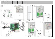
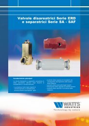
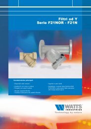
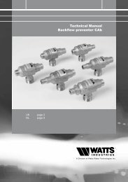
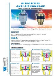
COMPONENTS FOR SANITARY SYSTEMAUTOMATIC CONTROL VALVEAutomatic self-acting control valve SERIES EU100the valve (also valve combinations) are as follows: - shut-off-check-reduction, stabilization ofThe more advanced models are equipped with a central control unit (EU900), of AISI 303stainless steel construction, which allows the regulating action to be performed as required byThe pilot devices serve for determining the type of function and the set-point of the parameterunder control. All valves are provided with visual indication of the valve plug stem position.161Technical characteristics common to all modelsValve body and cover Malleable cast iron GGG40 with1Stem guide in the coverSelf-lubricating bronzeInner valve parts Steel AISI (316, 303, 302)Piattelli membrana Steel ASTM AA 36 (DN 50-150)or cast iron GGG25 (DN 200-600)with full epoxy liningPlug seal and diaphragmBody and cover, pilot deviceNitrile rubber BUNA N 70 ShNickel-plated bronzeClosing speedCS6543210Opening speedOS2 10 3456234Piping and fittings, pilot circuit Nickel-plated brassMinimum operating0.25 bar (standard spring)differential pressure0.50 bar (reinforced spring)Max. operating temperature 70 °CReaction speedRS2 10 34565FUNCTIONSThe self-acting valves of Series EU100 consist of a main two-waybody of globe type Fig 1, whose flow section is controlled by ashaped plug actuated by the energy supplied by the flow undercontrol through a diaphragm inserted between the body and cover toform the operating chamber. When a small quantity of the fluid flowsthrough the water control circuit, this circuit places the following portsin communication with each other :- upstream port with pressure generally higher- downstream port with pressure generally lower- port of the operating chamber with regulated intermediate pressure.EU9001 Outlet connection towards the control chamber2 Setting of closing speed3 Setting of opening speed64 Outlet connection towards the pilot5 Calibration of the gradient of response to deviations6 Inlet connection of the upstream port7 Positioning of plate padlock7An adjustable throttle is installed at the outlet of the upstream port,and before communication with the operating chamber. The pilotdevice is installed at the inlet of the downstream port. When the pilotdevice is fully open Fig 2 it allows direct discharge of the operatingfluid coming from the upstream port; this causes a drop in pressuredue to the throttling and determines a low level of pressure in theoperating chamber and discharge of the latter.The valve plug is raised to full opening position, thrust by the fluidunder control. The fully closed pilot device Fig 3 causes the samehigh pressure present on upstream side to be present in theoperating chamber (throttling with zero flow does not cause drops)and determines the fluid under control to be shut-off. When the pilotdevice is in intermediate position Fig 4 it allows partial discharge ofthe operating fluid coming from the upstream port; this produces aproportional drop in pressure due to the throttling and determines, inthe operating chamber, an intermediate level of pressure and volume. Hence the valve plug modulates the lifting of the valve plug (inopening or in closing) thus ensuring that the required levels of flowor pressure are reached.Fig. 1Fig. 3Fig. 2Fig. 4MNO