EprogW32 101.pdf - TR Electronic
EprogW32 101.pdf - TR Electronic
EprogW32 101.pdf - TR Electronic

You also want an ePaper? Increase the reach of your titles
YUMPU automatically turns print PDFs into web optimized ePapers that Google loves.
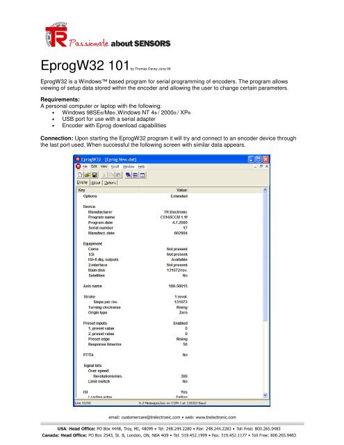
<strong>EprogW32</strong> 101by Thomas Davey June 09<strong>EprogW32</strong> is a Windows based program for serial programming of encoders. The program allowsviewing of setup data stored within the encoder and allowing the user to change certain parameters.Requirements:A personal computer or laptop with the following:• Windows 98SE®/Me® ,Windows NT 4® / 2000® / XP®• USB port for use with a serial adapter• Encoder with Eprog download capabilitiesConnection: Upon starting the <strong>EprogW32</strong> program it will try and connect to an encoder device throughthe last port used. When successful the following screen with similar data appears.
The screen contains multiple sections containing unique information about the connected encoder.These sections with an explanation of each are as follows:Options: You can choose between standard and extended options.Device: This section displays the device type, manufacturer, program name, version and date, serialnumber and date of manufacture.Equipment: Displays the integrated interfaces. This is preset at the factory and can not be changedwithout modification to unit. The “Main Disk” line shows the resolution as step number per revolution. Inthe “Satellite” line the measuring range is shown as number of revolutions.Axis Name: Part number of core used. In this line you can enter any text you like to describe the axisused.Stroke: Section for programming the resolution, measuring range, the counting direction and the initialvalue. Usually set at the factory but can be modified.Preset Inputs: For selecting preset values, the starting edge and response time.PT/TA: Section for setting serial programming with the hand terminal PT100. This section is only visiblewith extended options.Signal bits: Section for programming the speed monitor and the limit switch. This section is only visiblewith extended options. Here you can specify the allowed maximum speed and the switch on or off pointsof the four limit switches. The maximum speed can only be between 30 and 6000 revolutions per minute.Cams: If cams are possible with the device this is the section for programming the device as a camcontroller. You can have cams as an output via all interfaces except ISI and Switch outputs .Interface Section: There is one section for each available interface. For example SSI, ISI or ParallelActual Values: This section displays the position, the velocity, errors that occurred and bit patterns. Onlythe position value can be changed. Cam position is displayed if CAMs is selected as the output interface.Velocity is shown in RPM for rotary encoder and in mm/sec for linear encoders.
<strong>TR</strong> <strong>Electronic</strong> Center of Technical Excellence will work with you to develop custom<strong>TR</strong>aining to meet your needs.For Further Information Contact:training@trelectronic.com