Download a datasheet for the OMNI-HD1K Flow Meter here..
Download a datasheet for the OMNI-HD1K Flow Meter here..
Download a datasheet for the OMNI-HD1K Flow Meter here..
- No tags were found...
You also want an ePaper? Increase the reach of your titles
YUMPU automatically turns print PDFs into web optimized ePapers that Google loves.
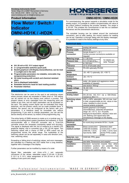
Honsberg Instruments GmbHTenter Weg 2-8 ● 42897 Remscheid ● GermanyFon +49 (0) 2191 - 9672 - 0 ● Fax - 40www.honsberg.com ● info@honsberg.comProduct In<strong>for</strong>mation<strong>Flow</strong> <strong>Meter</strong> / Switch /Indicator<strong>OMNI</strong>-<strong>HD1K</strong> / -HD2K<strong>OMNI</strong>-<strong>HD1K</strong> / <strong>OMNI</strong>-HD2KFor commissioning, <strong>the</strong> sensor supports a simulation mode <strong>for</strong> <strong>the</strong>analog output. It is possible to create a programmable mA value at<strong>the</strong> output (without modifying <strong>the</strong> process variable). The range is0..20 mA. This enables <strong>the</strong> commissioner to test <strong>the</strong> run between<strong>the</strong> sensor and <strong>the</strong> downstream electronics.The complete housing can be rotated around <strong>the</strong> mechanicalconnection, and so after sealing, <strong>the</strong> correct position <strong>for</strong> readingcan be set. Operation is through dialog with <strong>the</strong> display messages.It is possible to reset to <strong>the</strong> factory settings at any time.Technical data●●●●●●●●0/4..20 mA or 0/2..10 V output signal2 x programmable switches (push-pull)Backlit graphical LCD-Display (transreflective), can be readin sunlight and in <strong>the</strong> darkProgrammable parameters via rotatable, removable ring(programming protection)All metal housing with scratch and chemical resistantglassUnit is displayed (selectable)Rotatable electronic head <strong>for</strong> best reading positionParameter interfaceCharacteristicsThe electronics can be used on <strong>the</strong> spot to set switching valuesw<strong>here</strong> process values are exceeded or fallen short of. This settingcan be carried out via <strong>the</strong> display even without a process. Thepresent values or error messages from <strong>the</strong> measuring point arevisible at any time, and all major parameters can be accessed on<strong>the</strong> spot. The analog current signal can be evaluated from largedistances, and <strong>the</strong> present values can be made available <strong>the</strong>re. Ifdesired, <strong>the</strong> sensor can be configured at <strong>the</strong> factory with yourparameters. It is <strong>the</strong>re<strong>for</strong>e ready <strong>for</strong> immediate use, withoutprogramming. If you wish to change parameters, you can set <strong>the</strong>device directly at <strong>the</strong> sensor, by means of <strong>the</strong> programming ring.The entire family of <strong>OMNI</strong> sensors is made up in a modular way, bymeans of a building-block system (hardware and software). A 16-bitmicrocontroller with a 14-bit A/D converter and a 12-bit D/Aconverter ensure <strong>the</strong> necessary processing speed and accuracy.The signal is displayed with <strong>the</strong> unit of measure by a backlit LCDgraphical display, and is converted into a 0/4..20 mA signal. Twoswitching values with a choice of PNP or NPN output can beprogrammed across <strong>the</strong> whole range. The hystereses of <strong>the</strong>switching values can be set separately in value and direction (min.,max. switching value).Exceeding or falling short of switching values, and error messages,are indicated by a flashing red LED visible from a long distance,toge<strong>the</strong>r with a message in <strong>the</strong> display.Fur<strong>the</strong>r parameters can be modified by means of a code:Signal filter, selectable unit (l/min, m 3 /h ...) incl. automaticconversion of <strong>the</strong> values, selectable output 0..20 mA, 4..20 mA,0..10 V or 2..10 V, value assignment of 0/4..20 mA or 0/2..10 V(setting of zero point and range).Sensoranalog hall sensorNominal width DN 8.0.25Processfemale thread G 1 / 4..G 1connection (fur<strong>the</strong>r process connections available onrequest)<strong>Meter</strong>ing range 0.1..80 l/min<strong>for</strong> details seePressure loss 0.4..3.5 bar at Q max.table "Ranges"Q max.to 100 l/minTolerance ±3 % of full scale valuePressurePN 200 optionally PN 500resistanceMedia-20..+85 °C optionally -20..+150 °CtemperatureAmbient-20..+70 °CtemperatureMediawater, oils (gases and aggressive mediaavailable on request)Wiringsee section "Wiring"Supply voltage 18..30 V DCPower< 1 WconsumptionAnalog output 0/4..20 mA, 0/2..10 V via a 500 OhmΩresistance after 0 V.Switching values PNP or NPN, selectable, 300 mA max. loadS1 + S2in total, programmable as min. value or max.value, resistant to short circuits,reversal polarity protected.Displaybacklit graphical LCD-Display(transreflective), extended temperaturerange -20..+70 °C, 32 x 16 pixels,background illumination, displays value andunit, flashing LED signal lamp withsimultaneous message on <strong>the</strong> display.Ingress protection IP 67Electrical<strong>for</strong> round plug connector M12x1, 5-poleconnectionMaterialsmedium-contactMaterials, nonmedium-contactWeightInstallationlocationBrass construction:CW614N nickelled,CW614N, 1.4310,hard ferrite, NBRCW614N, PPS, glassStainless steelconstruction: 1.4571,1.4404, 1.4310, hardferrite PTFE-coated,FKMsee table "Dimensions and weights"Standard: horizontal inwards flow; o<strong>the</strong>rinstallation positions are possible; <strong>the</strong>installation position affects <strong>the</strong> display,metering and switching range.pi-ho_fki-omni-hd1k_e V1.00-01 1
Honsberg Instruments GmbHTenter Weg 2-8 ● 42897 Remscheid ● GermanyFon +49 (0) 2191 - 9672 - 0 ● Fax - 40www.honsberg.com ● info@honsberg.comProduct In<strong>for</strong>mationRangesDetails in <strong>the</strong> table correspond to horizontal inwards flow withincreasing flow rate.Standard type <strong>OMNI</strong>-<strong>HD1K</strong><strong>Meter</strong>ing rangel/min H 2OQ max.recommendedPressure lossbar at Q max. H 2O0.1 - 1 6 0.40.5 - 5 10 0.51.0 - 10 20 0.62.0 - 20 30 0.43.0 - 30 404.0 - 40 60 0.86.0 - 60 80 1.420.0 - 80 100 1.6Special ranges are available.Viscosity compensated type <strong>OMNI</strong>-HD2K<strong>Meter</strong>ingrangel/min oil30..330mm²/sQ max.recommendedPressure lossbar at Q max.oil mm²/s30 60 100 205 330Viscositystability±8 %, min.0.5 - 8 12 1.1 1.4 1.6 2.8 3.5 ±0.3 l/min1.5 - 15 22 2.2 2.3 2.4 ±0.5 l/min2.5 - 25 35 1.9 2.0 2.1 2.3 2.9 ±0.8 l/min6.0 - 40 60 2.6 ±2.7 l/min12.0 - 60 80 2.1 2.3 2.4 2.6 2.8 ±3.0 l/minSpecial ranges are available.Wiring12345brownwhiteblueblackgreyConnection example:Z=LoadZPNPZNPN18..30 V DCanalog output0 Vswitching signal 1switching signal 2Dimensions and weights<strong>OMNI</strong>-<strong>HD1K</strong> / <strong>OMNI</strong>-HD2KG Types SW X WeightkgBrass G 1 / 4 ...-008GM 40 15 1.6G 3 / 8 ...-010GMG 1 / 2 ...-015GM 1.5G 3 / 4 ...-020GM 18G 1 ...-025GM 1.4Stainless G 1 / 4 ...-008GK 41 15 1.6steelG 3 / 8 ...-010GKG 1 / 2 ...-015GK 1.5G 3 / 4 ...-020GK 18G 1 ...-025GK 1.4Handling and operationNote●●Include straight calming section of 5 x DN in inlet and outletInclude a filter if <strong>the</strong> media are dirty (use magnetic filter <strong>for</strong>ferritic components)ProgrammingThe annular gap of <strong>the</strong> programming ring can be turned to positions1 and 2. The following actions are possible:Set to 1 = continue (STEP)Set to 2 = modify (PROG)23154Neutral position between1 and 2The ring can be removed to act as a key, or turned through 180 °and replaced to create a programming protector.Operation is by dialog with <strong>the</strong> display messages, which makes itsuse very simple.Starting from <strong>the</strong> normal display (currently measured value withunit), if 1 (STEP) is repeatedly selected, <strong>the</strong>n <strong>the</strong> display shows <strong>the</strong>following in<strong>for</strong>mation in this order:2 pi-ho_fki-omni-hd1k_e V1.00-01
Honsberg Instruments GmbHTenter Weg 2-8 ● 42897 Remscheid ● GermanyFon +49 (0) 2191 - 9672 - 0 ● Fax - 40www.honsberg.com ● info@honsberg.comProduct In<strong>for</strong>mationDisplay of <strong>the</strong> parameters, using position 1● Switching value S1 (switching point 1 in <strong>the</strong> selected unit)● Switching characteristic of S1● (MIN = monitoring of minimum value, hysteresis greater thanswitching value,● MAX = monitoring of maximum value, hysteresis less than switchingvalue)● Hysteresis 1 (hysteresis value of S1 in <strong>the</strong> set unit)● Switching value S2● Switching characteristic of S2● Hysteresis 2● Code:After entering <strong>the</strong> code 111, fur<strong>the</strong>r parameters can be defined:● Filter (settling time of <strong>the</strong> display and output)● Units: e.g. l/min or m³/h● Output: 0..20 mA or 4..20 mA● 0/4 mA (flow rate corresponding to 0/4 mA)● 20 mA (flow rate corresponding to 20 mA)Edit, using position 2If <strong>the</strong> currently visible parameter is to be modified:● Turn <strong>the</strong> annular gap to position 2, so that a flashing cursorappears which displays <strong>the</strong> position which can be modified.● By repeatedly turning to position 2, values are increased; byturning to position 1, <strong>the</strong> next digit is reached.● Leave <strong>the</strong> parameter by turning to position 1 (until <strong>the</strong> cursorleaves <strong>the</strong> row); this accepts <strong>the</strong> modification.● If <strong>the</strong>re is no action within 30 seconds, <strong>the</strong> device returns to <strong>the</strong>normal display range without accepting <strong>the</strong> modification.The S1 and S2 limit switches can be used to monitor minima ormaxima.With a minimum-switch, falling below <strong>the</strong> limit value causes a switchoverto <strong>the</strong> alarm state. Return to <strong>the</strong> normal state occurs when<strong>the</strong> limit value plus <strong>the</strong> set hysteresis is once more exceeded.Min+HystMinTWith a maximum-switch, exceeding <strong>the</strong> limit value causes a switchoverto <strong>the</strong> alarm state. Return to <strong>the</strong> normal state occurs when<strong>the</strong> measured value once more falls below <strong>the</strong> limit value minus <strong>the</strong>set hysteresis.Tnormalalarmnormalt<strong>OMNI</strong>-<strong>HD1K</strong> / <strong>OMNI</strong>-HD2KWhile in <strong>the</strong> normal state <strong>the</strong> switching outputs are at <strong>the</strong> level of<strong>the</strong> supply voltage; in <strong>the</strong> alarm state <strong>the</strong>y are at 0 V, so that a wirebreak would also display as an alarm state at <strong>the</strong> signal receiver.Overload of <strong>the</strong> switching output is detected, indicated on <strong>the</strong>display ("Check S1 / S2"), and <strong>the</strong> switching output is switched off.Simulation modeTo simplify commissioning, <strong>the</strong> sensor supports a simulation mode<strong>for</strong> <strong>the</strong> analog output. It is possible to create a programmable valuein <strong>the</strong> range 0..26 mA at <strong>the</strong> output (without modifying <strong>the</strong> processvariable). This allows <strong>the</strong> wiring run between <strong>the</strong> sensor and <strong>the</strong>downstream electronics to be tested during commissioning. This ismode is accessed by means of code 311.Overload displayOverload of <strong>the</strong> switching output is detected, indicated on <strong>the</strong>display, and <strong>the</strong> switching output is set to high impedance.Default settingAfter setting <strong>the</strong> configuration parameters, <strong>the</strong>y can be reset tofactory values at any time, by means of Code 989.Starting from <strong>the</strong> normal display (currently measured value withunit), if 1 (STEP) is selected repeatedly, <strong>the</strong>n <strong>the</strong> display shows <strong>the</strong>following in<strong>for</strong>mation:Display of <strong>the</strong> parameters, using position 1● Switching values S1 and S2: Switching values in <strong>the</strong> selectedunit.● Hysteresis direction of S1 and S2:Max = Hysteresis less than S1 or S2● Max = Hysteresis greater than S1 or S2● Hystereses Hyst 1 and Hyst 2:● Hysteresis values of <strong>the</strong> switching values in <strong>the</strong> setunit● After entering code 111, fur<strong>the</strong>r parameters can be defined (thisshould take place only if necessary)● Filter: Selectable filter constant in seconds (affects display andoutput)● Unit: e.g. bar or psi ...● Output: 0..20 mA or 4..20 mA● 0/4 mA: Displayed value <strong>for</strong> 0/4 mA● 20 mA: Displayed value <strong>for</strong> 20 mAEdit, using position 2●●If <strong>the</strong>visible parameter is to be modified:Turn <strong>the</strong> annular gap to position 2, so that a flashing cursorappears which displays <strong>the</strong> position which can be modified. Byrepeatedly turning to position 2, values are increased; byturning to position 1, <strong>the</strong> next digit is reached. In this way, everydigit can be modified. If <strong>the</strong>re is no action within 5 seconds, <strong>the</strong>device returns to <strong>the</strong> normal display range without accepting<strong>the</strong> modification.Saving <strong>the</strong> changes using position 1●After leaving <strong>the</strong> last value, turn once to position 1; this accepts<strong>the</strong> modification.MaxMax-HystnormalalarmnormalThe change to <strong>the</strong> alarm state is indicated by <strong>the</strong> integrated redLED and a cleartext in <strong>the</strong> display.tpi-ho_fki-omni-hd1k_e V1.00-01 3
Honsberg Instruments GmbHTenter Weg 2-8 ● 42897 Remscheid ● GermanyFon +49 (0) 2191 - 9672 - 0 ● Fax - 40www.honsberg.com ● info@honsberg.comProduct In<strong>for</strong>mationOrdering codeThe basic device is ordered e.g. <strong>HD1K</strong>-015GM005E wi<strong>the</strong>lectronics e.g. <strong>OMNI</strong>-<strong>HD1K</strong>S<strong>OMNI</strong>-HD1. 2. 3. 4. 5. 6.HD - G E7. 8. 9.S1. Construction1K standard2K viscosity compensated2. Nominal width008 DN 8 - G 1 / 4010 DN 10 - G 3 / 8015 DN 15 - G 1 / 2020 DN 20 - G 3 / 4025 DN 25 - G 13. Process connectionG female thread4. Connection materialM brassK stainless steel5.<strong>HD1K</strong> - <strong>Meter</strong>ing range H 2O <strong>for</strong> horizontalinwards flow001 0.1 - 1 l/min l005 0.5 - 5 l/min l010 1.0 - 10 l/min l020 2.0 - 20 l/min l030 3.0 - 30 l/min l040 4.0 - 40 l/min l060 6.0 - 60 l/min l080 20.0 - 80 l/min lHD2K - metering range oil 30..330 mm 2 /s<strong>for</strong> horizontal inwards flow008 0.5 - 8 l/min l015 1.5 - 15 l/min l025 2.5 - 25 l/min l040 6.0 - 40 l/min l060 12.0 - 60 l/min l6. Connection <strong>for</strong>E electronics l lOptions<strong>OMNI</strong>-<strong>HD1K</strong> / <strong>OMNI</strong>-HD2K● Tropical model (completely oil-filled <strong>for</strong> severe externalapplications or <strong>for</strong> rapidly changing temperatures. Reliablyprevents condensation).● Measured values <strong>for</strong> oil or gas● Special quantities● Version <strong>for</strong> 150 °C● Temperature display 0..120 °C● Rein<strong>for</strong>ced pistonAccessoires●Cable/round plug connector (KB...)see additional in<strong>for</strong>mation “Accessories”Ordering in<strong>for</strong>mation● Specify direction of flow, medium, and metering range.● For viscous media specify viscosity, temperature, and medium(e.g. ISO VG 68) (enquire about metering range).● For gases, state pressure (relative or absolute), temperatureand medium (e.g. air) (request metering range)Combinations with <strong>OMNI</strong><strong>OMNI</strong>-converter / counter can be combined with very differenttypes of pickup systems <strong>for</strong> flow rate, level, temperature, andpressure. This has created a family ofsensors with which different types ofapplications can be supported.7. For base device1K standard l2K viscosity compensated l8. Electrical connectionS <strong>for</strong> round plug connector M12x1, 5-pole9. OptionalH m model with gooseneck4 pi-ho_fki-omni-hd1k_e V1.00-01


