TF PE englisch - Steinle Industriepumpen GmbH
TF PE englisch - Steinle Industriepumpen GmbH
TF PE englisch - Steinle Industriepumpen GmbH

You also want an ePaper? Increase the reach of your titles
YUMPU automatically turns print PDFs into web optimized ePapers that Google loves.
G:\Betriebsanleitungen\<strong>TF</strong>\<strong>TF</strong> <strong>PE</strong> english.P65 01.09.2000<br />
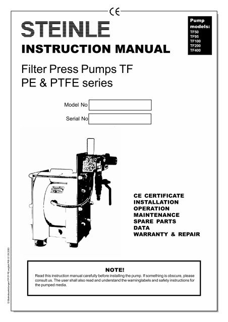
INSTRUCTION MANUAL<br />
Filter Press Pumps <strong>TF</strong><br />
<strong>PE</strong> & P<strong>TF</strong>E series<br />
Model No<br />
Serial No<br />
NOTE!<br />
Read this instruction manual carefully before installing the pump. If something is obscure, please<br />
consult us. The user shall also read and understand the warninglabels and safety instructions for<br />
the pumped media.<br />
Pump<br />
models:<br />
<strong>TF</strong>50<br />
<strong>TF</strong>95<br />
<strong>TF</strong>100<br />
<strong>TF</strong>200<br />
<strong>TF</strong>400<br />
CE CERTIFICATE<br />
INSTALLATION<br />
O<strong>PE</strong>RATION<br />
MAINTENANCE<br />
SPARE PARTS<br />
DATA<br />
WARRANTY & REPAIR
CHAPTER<br />
CE CERTIFICATE 3<br />
1 INSTALLATION 4<br />
1.1 Receiving inspection 4<br />
1.2 Storage 4<br />
1.3 Foundation 4<br />
1.4 Suction and discharge piping 4<br />
1.4.1 Turnable connections 4<br />
1.4.2 Connection of suction pipe 4<br />
1.4.3 Connection of discharge pipe 4<br />
1.5 Air connection 4<br />
1.5.1 Air treatment system 5<br />
1.5.2 Version <strong>TF</strong>F<br />
1.6 Muffler 5<br />
1.7 Example installation 5<br />
1.8 Scope of supply 6<br />
2 O<strong>PE</strong>RATION 7<br />
2.1 Health and safety 7<br />
2.1.1 Protection 7<br />
2.1.2 Environments in danger of explosion 7<br />
2.1.3 Air pressure 7<br />
2.1.4 Noise level 7<br />
2.1.5 Temperature hazards 7<br />
2.2 Before starting the pump 7<br />
2.3 Starting and operating 8<br />
2.3.1 Dry running 8<br />
2.3.2 Optimizing the pump lifetime 8<br />
2.4 Pump stopping 8<br />
3 MAINTENANCE 9<br />
3.1 Performance test 9<br />
3.2 Routine inspection 9<br />
3.3 Complete inspection 9<br />
3.4 Location of faults 9<br />
3.5 Dismantling the pump 10<br />
CONTENTS<br />
Page 2<br />
3.5.1 Before the dismantling procedure 10<br />
3.5.2 Mainparts 10<br />
3.5.3 Housing 10<br />
3.5.4 Center block 10<br />
3.6 Assembly of the pump 11<br />
3.6.1 Center block 11<br />
3.6.2 Suction and discharge connections 11<br />
3.6.3 Assembling of the main units 11<br />
3.6.4 Test run 11<br />
4 SPARE PARTS 12<br />
4.1 Spare part drawing <strong>TF</strong>50 - <strong>TF</strong>400 12<br />
4.2 Spare part list <strong>TF</strong>50 13<br />
4.3 Spare part list <strong>TF</strong>95/100 13<br />
4.4 Spare part list <strong>TF</strong>200 14<br />
4.5 Spare part list <strong>TF</strong>400 14<br />
4.6 Stocking recommendation 15<br />
4.7 How to order parts 15<br />
4.8 Pump code 15<br />
5 DATA 16<br />
5.1 Performance curves 16<br />
5.2 Dimensions 17<br />
5.3 Technical data 17<br />
6 WARRANTY & REPAIR 18<br />
6.1 Returning parts 18<br />
6.2 Warranty 18<br />
6.3 Warranty form 19<br />
INTRODUCTION<br />
The STEINLE <strong>TF</strong> filter press pump is very compact pump system, which can be installed directly at the filter<br />
press. The pumps are designed to be safe simple and easy to use and maintain. The construction is sealless and<br />
without rotating parts. The pumps are suitable for almost all different kinds of even aggressive slurries used by the<br />
industry today. It is air driven and needs no further equipment to control the flow rate when the pressure in the filter<br />
press rises up. Pressure regulator and needle valve are already installed at the pump.<br />
The pumps are based on the aproved Tapflo-pumps, which are exceptionally qualified for this application.<br />
With proper attention to maintenace, the <strong>TF</strong>-series will give efficient and trouble free operation. This instruction<br />
manual will familiarise operators with detailed information about installing, operating and maintaining the pump.
CHAPTER<br />
CE CERTIFICATE<br />
Declaration of conformity<br />
Machinery directive 89/392/EEC, Annex 2A<br />
STEINLE <strong>Industriepumpen</strong> declares that:<br />
Product name: Filter Press Pumps<br />
Models: <strong>TF</strong>…<br />
Is in conformity with the essential health and safety requirements and technical<br />
construction file requirements of the EC Machinery directive 89/393/EEC with<br />
amendments 91/368/EEC, 93/94 EEC and 93/68 EEC.<br />
Manufacturer: STEINLE <strong>Industriepumpen</strong><br />
Address: Varnhagenstr. 42<br />
D-40225 Düsseldorf<br />
Germany<br />
Düsseldorf, September 1st 2000<br />
Michael <strong>Steinle</strong><br />
Managing director<br />
Page 3
1 INSTALLATION<br />
CHAPTER<br />
1.1 Receiving inspection<br />
Although precaution is taken by us when packing and shipping, we urge you to carefully check the<br />
shipment on receipt. Make sure that all parts and accesories listed on the packing list are accounted<br />
forImmediately report any damage or shortage to the transport company and to STEINLE<br />
<strong>Industriepumpen</strong>.<br />
1.2 Storage<br />
If the equipment is to be stored prior to installation, place it in a clean location. Do not remove the<br />
protective covers from the suction, discharge and air connections which have been fastened to keep<br />
pump internals free of debris. Clean the pump thoroughly before installation.<br />
1.3 Foundation<br />
The pump is furnished with vibration absorbing rubber feet. They have an female thread to being fixed<br />
to a foundation. Make sure the foundation is able to absorb vibrations.<br />
It is essential for the operation of the pump to mount the pump with the feet in a downward direction<br />
(see sketch).<br />
1.4 Suction and discharge pipings<br />
Suction and discharge piping should be fully supported and anchored near to but independent of the<br />
pump. The piping to the pump should be a hose, to prevent undue stress and strain on the pump<br />
connections and the pipings.<br />
1.4.1 Turnable connections<br />
The suction and discharge connections are turnable 180°. This simplifies the assembling and installation<br />
considerably. If you wish to turn the connections, screw a threaded nipple into the connection<br />
and turn. Be careful so that the threads do not get damaged. On the larger models <strong>TF</strong>200 and <strong>TF</strong>400<br />
it will simplify if the housing nuts are slightly released while turning the connections.<br />
1.4.2 Connection of suction pipe<br />
Remember that the suction pipe/connection is the most critical point, especially if the pump is<br />
priming. Just a small leakage will dramatically reduce the suction capability of the pump. When<br />
connecting the suction pipe, following is recommended.<br />
1) For satisfactory operation, use reinforced hose or corresponding (the suction power may otherwise<br />
shrink the hose). The internal diameter of the hose should be the same as on the suction connection<br />
(at the bottom of the pump) to have best suction capability.<br />
2) Make sure that the connection hose - pump is completely tight, otherwise the suction capability<br />
will be reduced.<br />
3) Always use as short suction pipe as possible. Avoid air pockets which can arise with long pipings.<br />
1.4.3 Connection of discharge pipe<br />
For this connection it is only recommended a simple and positive flow connection. Use a hose or<br />
flexible piping (minimum one meter) between the discharge connection and any rigid fixed piping.<br />
Coil the hose at least one turn. All components (hose, pipe, valves etc) on the discharge piping must<br />
be designed for minimum PN 16.<br />
1.5 Air connection<br />
Screw the air hose into the air intake on the pressure booster on the pump with for example a<br />
bayonet coupling. For best efficiency, use the same hose diameter as the internal diameter of the<br />
connection on the air intake. The maximum air pressure for <strong>TF</strong>50-<strong>TF</strong>100 is 8 bar, for <strong>TF</strong>200-<strong>TF</strong>400<br />
6 bar. For the <strong>TF</strong>F version the maximum pressure is the half of above.<br />
Page 4
CHAPTER<br />
1 INSTALLATION<br />
1.5.1 Air treatment system<br />
The air valve is constructed for oilfree air. Lubrication of the air is not allowed. Maximum air pressure<br />
is 8 bar. As prevention purpose some sort of filtration of the air is recommended. Dirt in the air can<br />
under unfortunate circumstances be the cause of breakdown. Dry air is also essential. Ice may<br />
appear in the air valve if the air is humid.<br />
To facilitate the operation of the pump we recommend an air treatment system connected to the air<br />
supply. These components should be included:<br />
1) Regulator to adjust the air pressure<br />
2) Manometer to read the actual pressure<br />
3) Filter<br />
These components are included in Tapflos Air treatment system which can be ordered from STEINLE<br />
<strong>Industriepumpen</strong>.<br />
1.5.2 Version <strong>TF</strong>F with pressure transmission 1 : 4<br />
� The first pressure booster, which is supplied as a single part, has to be installed external. This<br />
booster is connected with the air supply.<br />
� Between this external booster and the booster mounted at the pump, the air connection hose<br />
has to be plugged in. Please leave at least a length 1m of the hose.<br />
� The end pressure of the pump has to be adjusted at the booster mounted on the pump.<br />
1.6 Muffler<br />
The plastic muffler for thr pressure booster and the metallic muffler for the pump are supplied as<br />
singel parts because of transport safety. These mufflers has to be screwed into the pump.<br />
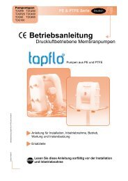
1.7 Example of installation<br />
Page 5
1 INSTALLATION<br />
CHAPTER<br />
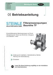
1.8 Scope of supply<br />
Page 6<br />
Muffler booster<br />
Pressure booster<br />
Pressure gauge (Option)<br />
Adjustment knob pressure<br />
Needle valve<br />
Ball valve<br />
Air connection<br />
Suction side
2<br />
CHAPTER<br />
O<strong>PE</strong>RATION<br />
2.1 Health and safety<br />
The pump must be installed according to local and national safety rules.<br />
The pumps are constructed for particular applications. Do not use the pump on applications<br />
different from that for which it was sold without consulting us to ascertain its suitability.<br />
2.1.1 2.1.1 Protection<br />
Protection<br />
In the interest of health and safety it is essential to wear protective clothing and safety goggles when<br />
operating, and/or working in the vicinity of STEINLE pumps.<br />
2.1.2 Environments in danger of explosion<br />
For use in environments in danger of explosion, the pump must be of conductive material and properly<br />
earthed. Follow the explosion safety rules applicable at the location for the pump. Consult us for<br />
further information. Incorrect installation or use may cause injury or death to personel in vicinity of the<br />
pump.<br />
2.1.3 Air pressure<br />
The maximum air pressure for STEINLE pumps is shown in chapter 1.5. Higher air pressure than 8<br />
bar can damage the pump and may cause injury to personel in vicinity of the pump.<br />
2.1.4 Noise level<br />
At tests, the noise level from a <strong>TF</strong> pump has not exceeded 80 dB(A). Under some circumstances, for<br />
example if the pump is operating under high air pressure at low discharge head, the noise can be<br />
inconvenient or hazardous for personel staying for long periods in vicinity of the pump. This hazard<br />
can be prevented by:<br />
- using suitable ear protection<br />
- lower the air pressure and/or raise the discharge head<br />
- lead the outcomming air from the place by connecting a hose from the muffler connection of the<br />
pump.<br />
- use elastomer valve balls EPDM or NBR instead of P<strong>TF</strong>E or stainless steel, provided that the<br />
elastomer is compatible with the pumped liquid.<br />
2.1.5 Temperature hazards<br />
Raised temperature can cause damage on the pump and/or pipings and may also be hazardous for<br />
personel in the vicinity of the pump/pipings. Avoid quick temperature changes and do not exceed the<br />
maximum temperature specified when the pump was ordered. See also general max temperatures<br />
based on water in chapter 5 "Data".<br />
2.2 Before starting the pump<br />
- Make sure the pump is installed accordning to the installation instruction (section 1).<br />
- Filling of the pump with liquid before start is not necessary.<br />
- When installing is new or reinstalled, a test run of the pump with water should be conducted to<br />
make sure the pump operates normally and does not leak.<br />
- Make sure that the maximum pressure for the pump and the piping is not exceeded.<br />
Page 7
CHAPTER<br />
2 O<strong>PE</strong>RATION<br />
2.3 Starting and operating<br />
- Open the discharge valve.<br />
- Note! Considering the suction capacity when air is still in the suction pipe, it is recommended<br />
to start with low air pressure/flow in the beginning. This is not necessary if the pump is<br />
filled with liquid before start.<br />
- When the pump has been filled with liquid, the air pressure/flow may be raised to increase the<br />
suction capacity of the pump.<br />
- The performance of the pump can be adjusted through the air supply by adjusting the needle valve<br />
and a pressure regulator. The performance can also be adjusted by normal flow control on the<br />
discharge side of the system.<br />
2.3.1 Dry running<br />
The pump may run dry without any problem for a shorter time. Dry running for a longer period causes<br />
an increase of wear due to the high stroke frequency.<br />
2.3.2 Optimizing the pump lifetime<br />
Running at full frequenzy (maximum air pressure/flow) continiously will cause premature wear of the<br />
components. As a general rule, we recommend to run at half of the maximum capacity of the pump.<br />
For instance, a <strong>TF</strong>120 pump should run continious maximum at 5 m³/h.<br />
2.4 Pump stopping<br />
When the filter press is filled and the maximum pressure is reached, the must be stopped by closing<br />
the air supply. Before the filter press is opended, the pressure has to drop down to 0.<br />
To stop the pump automatically, various solenoid valves are available.<br />
Stroke sensors can register the frequency of the pump. When the end pressure is reached, the<br />
pump moves slowly and a signal for stopping the filtration can be given.<br />
Page 8
CHAPTER<br />
3 MAINTENANCE<br />
3.1 Performance test<br />
When installation is new, a test run of the pump should be conducted. Gauge the capacity at specific<br />
air pressure/flow. This information is for use in checking performance as wear takes place. You will<br />
be able to set schedules for maintenance of the pump and to select spare parts to be kept on stock.<br />
3.2 Routine inspection<br />
Frequent observation of the pump operation is recommended to detect problems. A change in sound<br />
of the running pump can be an indication of weared parts (see below "location of faults"). Leaking<br />
liquid from the pump and changes of performance may also be detected. Routine inspections should<br />
be conducted when a malfunction is suspected.<br />
3.3 Complete inspection<br />
The intervals for a complete inspection depend upon the operation conditions for the pump. The<br />
characteristics of the liquid, temperature, materials used in the pump and running time decide how<br />
often a complete inspection is necessary.<br />
If a problem has occured, or if the pump is in need of a complete inspection, see later this chapter<br />
"location of faults" and "dismantling of the pump". You are of course warmly welcome to consult us<br />
for further help.<br />
Weared parts should be carried in stock, see chapter 4 "stocking recommendations".<br />
3.4 Location of faults<br />
Problem Possible fault<br />
The pump does not run The air pressure is to low<br />
The air connection is blocked<br />
Muffler is blocked<br />
Air valve is defect<br />
Dirt in the pump chamber<br />
Diaphragm breakdown<br />
The suction is bad Suction connection is not tight<br />
Suction connection is blocked<br />
Muffler is blocked<br />
Valve balls are blocked<br />
Valve balls are damaged<br />
The pump runs irregularly Valve balls are blocked<br />
Sealings are defect in air valve or center block<br />
Diaphragm breakdown<br />
Bad flow/pressure Pressurefall in incomming air<br />
Suction or air connection blocked<br />
Muffler is blocked<br />
Air valve is defect<br />
Valve balls worn out/broken<br />
Air in liquid<br />
Diaphragm breakdown<br />
Liquid leaks from the pump Screws on the housing not properly fastened<br />
Liquid comes out of the muffler Diaphragm breakdown<br />
Page 9
3 MAINTENANCE<br />
CHAPTER<br />
3.5 Dismantling the pump<br />
3.5.1 Before the dismantling procedure<br />
Be sure to drain all liquid from the pump. Cleanse or neutralize the pump thoroughly. Disconnect the<br />
air connection and then the suction and discharge connections.<br />
3.5.2 Mainparts<br />
3.5.3 Housing<br />
1) Pull out the air hose from the booster to the pump by pushing the ring on the fitting. Unscrew the<br />
nuts on one side of the housing and take the SS reinfoorcement sheet from the pump.<br />
2) Place the pump on the side that still has the nuts (the pump lays on the nuts) on a stable ground,<br />
for example a table.<br />
3) Carefully remove the "loose housing".<br />
4) Carefully lift up the suction and discharge connections. You have the center block and one of the<br />
housings with pin screws left.<br />
5) Upend the pump and carefully pull out the pin screws. Be careful with the diaphragms that easily<br />
can be damaged by the threads of the pin screws.<br />
The mainparts of the pump are now dismantled. The following is for dismantling the housing and<br />
center block in detail.<br />
1) Put the house wall with the flat side down on a plane surface that will not damage the housing, for<br />
example a table covered with cardboard.<br />
2) Take one of the pin screws. Screw it in the hole on the spacer sleeve and turn it as far as it is<br />
possible, until it lays upside down (180°) compared to the starting position. Lead the spacer<br />
sleeve carefully against the lower valve seat until it is free and can be put out. Please note that<br />
force never shall be used for dismantling. When the spacer sleeve does not turn, use a flat punch<br />
and push with slight hammer beats the spacer sleeve on one side till it turns.<br />
3) Stick something not pointed (for example a pin screw with one of the nuts on) into the hole for the<br />
discharge connection and press gently out the upper valve seat.<br />
4) Place one of the pin screws on the inside (behind) the valve ball stopper on the lower valve seat.<br />
Carefully pull out the valve seat in the housing.<br />
5) In order to remove the valve ball from the valve seat, use a pin screw and press carefully out the<br />
valve ball stopper and the valve ball will be free.<br />
3.5.4 Center block<br />
1) Press the diaphragms to their neutral position (both have the same distance to the center block).<br />
2) Hold one of the diaphragms and unscrew the other. Then pull out the remaining diaphragm with<br />
the diaphragm shaft.<br />
3) Place the center block on one of the housings. Observe that this is a faying surface, so be careful<br />
not to damage it. Place a piece of cardboard or similar underneath. Pull out the circlip carefully so<br />
it will not hurt you or disappear.<br />
4) Turn the center block. Pull out the other circlip.<br />
Page 10
3 MAINTENANCE<br />
CHAPTER<br />
5) Press carefully on the other air valve rear end in the same direction. The main piston and air valve<br />
housing will slowly come out. Observe that the brass is soft material and changes figure easy. If<br />
those details are deformed they must be changed, so handle thoose with care.<br />
The pump is now completely dismantled. Check all components for wear or damage and replace if<br />
necessary.<br />
3.6 Assembly of the pump<br />
3.6.1 Center block<br />
The center block is assembled in the same way as dismantling it but in opposite direction. Put the<br />
diaphragm with shaft into the center block. Screw the next diaphragm onto the shaft and fix the<br />
holes. Sometimes you have to turn the diaphragms a little back to get the holes fixed.<br />
3.6.2 Suction/discharge connections<br />
Always make sure that the o-rings are placed on the in/outlet before all assembling of pump.<br />
Special for pump with P<strong>TF</strong>E diaphragms:<br />
U-rings are placed on the pump housing. Put u-ring with open side up so you carefully can put the oring<br />
in the groove. Make sure you do not fold the inner edge of the u-ring.<br />
3.6.3 Assembling of the main units<br />
The housing is assembled in opposite order to dismantling:<br />
1) Turn the housing with the flat side up.<br />
2) Make sure all pin screws have one nut and one washer each. Nut should only be put on one or two<br />
threads.<br />
3) Put all the pin screws through the housing and then turn the housing so it rests on the nuts.<br />
4) Let the center block gently be put to the housing with screws through center block. Be careful<br />
that threads on screws do not damage the diaphragms when assembling.<br />
5) Place suction and discharge connections in their positions in the housing. Be careful not to<br />
damage the u-ring (P<strong>TF</strong>E model) and o-rings.<br />
6) Put the second housing onto the pin screws. Make sure that suction/discharge connections are<br />
in right direction and again be careful with the u-ring/o-rings.<br />
7) Fasten the nuts alternatingly by hand, with or without washers depending on how much of the<br />
thread comes out. When all nuts are fastened, turn them gently with a tool so that the pump gets<br />
closed. If some of the nuts were fastened without washer, unscrew thoose and put washers<br />
underneath. After a few weeks operation a follow up draft of the nuts is recommended.<br />
The pump is now ready for service and can be reinstalled in the system according to chapter 1 and<br />
2 (installation and operation).<br />
3.6.4 Test run<br />
We recommend you to conduct a test run of the pump before installing it to the system so no liquid<br />
gets wasted if the pump leaks or perhaps does not start according to wrong assembling of the pump.<br />
Page 11
4<br />
CHAPTER<br />
SPARE PARTS<br />
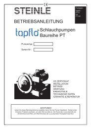
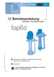
4.1 Spare part drawing <strong>TF</strong>50 - <strong>TF</strong>400<br />
Page 12
4<br />
CHAPTER<br />
4.2 Spare part list <strong>TF</strong>50<br />
Pos Description Material Qty Article No<br />
11 Housing <strong>PE</strong> 2 6-050-11<br />
P<strong>TF</strong>E 6-050-11-1<br />
12 Center block PP 1 6-050-12<br />
13 In/Outlet <strong>PE</strong> 2 6-050-13<br />
P<strong>TF</strong>E 6-050-13-1<br />
14 Pin screw AISI 316 6 6-050-14<br />
15 Diaphragm EPDM 2 6-050-15<br />
P<strong>TF</strong>E 6-050-15-1<br />
NBR 6-050-15-3<br />
16 Diaphragm shaft AISI 316 1 6-050-16<br />
17 Rubber foot NBR 4 6-050-17<br />
18 O-ring set (in/outlet) EPDM 4 6-050-18<br />
P<strong>TF</strong>E 6-050-18-1<br />
FKM (viton) 6-050-18-2<br />
19 Spacer sleeve <strong>PE</strong> 2 6-050-19<br />
P<strong>TF</strong>E 6-050-19-1<br />
20 Upper valve seat <strong>PE</strong> 2 6-050-20<br />
P<strong>TF</strong>E 6-050-20-1<br />
21 Lower valve seat <strong>PE</strong> 2 6-050-21<br />
P<strong>TF</strong>E 6-050-21-1<br />
22 Valve ball stop P<strong>TF</strong>E 4 6-050-22-1<br />
Pos Description Material Qty Article No<br />
11 Housing <strong>PE</strong> 2 6-100-11<br />
P<strong>TF</strong>E 6-100-11-1<br />
12 Center block PP 1 6-100-12<br />
13 In/Outlet <strong>PE</strong> 2 6-100-13<br />
P<strong>TF</strong>E 6-100-13-1<br />
14 Pin screw AISI 316 6 6-100-14<br />
15 Diaphragm EPDM 2 6-100-15<br />
P<strong>TF</strong>E 6-100-15-1<br />
NBR 6-100-15-3<br />
16 Diaphragm shaft AISI 316 1 6-100-16<br />
17 Rubber foot NBR 4 6-050-17<br />
18 O-ring set (in/outlet) EPDM 4 6-100-18<br />
P<strong>TF</strong>E 6-100-18-1<br />
FKM (viton) 6-100-18-2<br />
19 Spacer sleeve <strong>PE</strong> 2 6-100-19<br />
P<strong>TF</strong>E 6-100-19-1<br />
20 Upper valve seat <strong>PE</strong> 2 6-100-20<br />
P<strong>TF</strong>E 6-100-20-1<br />
21 Lower valve seat <strong>PE</strong> 2 6-100-21<br />
P<strong>TF</strong>E 6-100-21-1<br />
22 Valve ball stop <strong>PE</strong> 4 6-100-22<br />
P<strong>TF</strong>E 6-100-22-1<br />
SPARE PARTS<br />
4.3 Spare part list <strong>TF</strong>95/100<br />
Page 13<br />
Pos Description Material Qty Article No<br />
23 Valve ball EPDM 4 6-050-23<br />
P<strong>TF</strong>E 6-050-23-1<br />
NBR 6-050-23-3<br />
AISI 316 6-050-23-5<br />
PUR 6-050-23-7<br />
25 Muffler PP 1 6-050-25<br />
26 Air intake adapter Brass 1 6-050-26<br />
27 Circlip Phosph. br. 2 6-050-27<br />
30 O-ring NBR 6 6-050-30<br />
33 Plug <strong>PE</strong> 2 6-050-33<br />
P<strong>TF</strong>E 6-050-33-1<br />
36 Center block sealing <strong>PE</strong> 2 6-050-36<br />
37 Nut AISI 316 12 6-050-37<br />
38 Washer AISI 316 12 6-050-38<br />
43 O-ring (valve seat) EPDM 4 6-050-43<br />
P<strong>TF</strong>E 6-050-43-1<br />
FKM (viton) 6-050-43-2<br />
47 O-ring (back up for 36) NBR 2 6-050-47<br />
57 Nut cover <strong>PE</strong> 12 6-050-57<br />
61 Air valve complete 1 6-050-61<br />
70 Service Kit Booster 1 KTVBA1110<br />
Pos Description Material Qty Article No<br />
23 Valve ball EPDM 4 6-100-23<br />
P<strong>TF</strong>E 6-100-23-1<br />
NBR 6-100-23-3<br />
AISI 316 6-100-23-5<br />
PUR 6-100-23-7<br />
25 Muffler PP 1 6-100-25<br />
26 Air intake adapter Brass 1 6-050-26<br />
27 Circlip Phosph. br. 2 6-050-27<br />
30 O-ring NBR 6 6-050-30<br />
33 Plug <strong>PE</strong> 2 6-100-33<br />
P<strong>TF</strong>E 6-100-33-1<br />
36 Center block sealing <strong>PE</strong> 2 6-100-36<br />
37 Nut AISI 316 12 6-200-37<br />
38 Washer AISI 316 12 6-200-38<br />
43 O-ring (valve seat) EPDM 4 6-100-43<br />
P<strong>TF</strong>E 6-100-43-1<br />
FKM (viton) 6-100-43-2<br />
47 O-ring (back up for 36) NBR 4 6-100-47<br />
57 Nut cover <strong>PE</strong> 12 6-200-57<br />
61 Air valve complete 1 6-050-61<br />
70 Service Kit Booster for <strong>TF</strong>100 1 KTVBA2100<br />
for <strong>TF</strong>95 1 KTVBA1110
4<br />
CHAPTER<br />
4.4 Spare part list <strong>TF</strong>200<br />
Pos Description Material Qty Article No<br />
11 Housing <strong>PE</strong> 2 6-200-11<br />
P<strong>TF</strong>E 6-200-11-1<br />
12 Center block PP 1 6-200-12<br />
13 In/Outlet <strong>PE</strong> 2 6-200-13<br />
P<strong>TF</strong>E 6-200-13-1<br />
14 Pin screw AISI 316 8 6-200-14<br />
15 Diaphragm EPDM 2 6-200-15<br />
P<strong>TF</strong>E 6-200-15-1<br />
NBR 6-200-15-3<br />
16 Diaphragm shaft AISI 316 1 6-200-16<br />
17 Rubber foot NBR 4 6-400-17<br />
18 O-ring set (in/outlet) EPDM 4 6-200-18<br />
P<strong>TF</strong>E 6-200-18-1<br />
FKM (viton) 6-200-18-2<br />
19 Spacer sleeve <strong>PE</strong> 2 6-200-19<br />
P<strong>TF</strong>E 6-200-19-1<br />
20 Upper valve seat <strong>PE</strong> 2 6-200-20<br />
P<strong>TF</strong>E 6-200-20-1<br />
21 Lower valve seat <strong>PE</strong> 2 6-200-21<br />
P<strong>TF</strong>E 6-200-21-1<br />
4.5 Spare part list <strong>TF</strong>400<br />
Pos Description Material Qty Article No<br />
11 Housing <strong>PE</strong> 2 6-400-11<br />
P<strong>TF</strong>E 6-400-11-1<br />
12 Center block PP 1 6-400-12<br />
13 In/Outlet <strong>PE</strong> 2 6-400-13<br />
P<strong>TF</strong>E 6-400-13-1<br />
14 Pin screw AISI 316 8 6-400-14<br />
15 Diaphragm EPDM 2 6-400-15<br />
P<strong>TF</strong>E 6-400-15-1<br />
NBR 6-400-15-3<br />
16 Diaphragm shaft AISI 316 1 6-400-16<br />
17 Rubber foot NBR 4 6-400-17<br />
18 O-ring set (in/outlet) EPDM 4 6-400-18<br />
P<strong>TF</strong>E 6-400-18-1<br />
FKM (viton) 6-400-18-2<br />
19 Spacer sleeve <strong>PE</strong> 2 6-400-19<br />
P<strong>TF</strong>E 6-400-19-1<br />
20 Upper valve seat <strong>PE</strong> 2 6-400-20<br />
P<strong>TF</strong>E 6-400-20-1<br />
21 Lower valve seat <strong>PE</strong> 2 6-400-21<br />
P<strong>TF</strong>E 6-400-21-1<br />
22 Valve ball stop <strong>PE</strong> 4 6-400-22<br />
P<strong>TF</strong>E 6-400-22-1<br />
SPARE PARTS<br />
Page 14<br />
Pos Description Material Qty Article No<br />
22 Valve ball stop <strong>PE</strong> 4 6-200-22<br />
P<strong>TF</strong>E 6-200-22-1<br />
23 Valve ball EPDM 4 6-200-23<br />
P<strong>TF</strong>E 6-200-23-1<br />
NBR 6-200-23-3<br />
PU (polyurethane) 6-200-23-7<br />
AISI 316 6-200-23-5<br />
25 Muffler PP 1 6-100-25<br />
26 Air intake adapter Brass 1 6-400-26<br />
27 Circlip Phosph. br. 2 6-400-27<br />
30 O-ring NBR 6 6-400-30<br />
33 Plug <strong>PE</strong> 2 6-200-33<br />
P<strong>TF</strong>E 6-200-33-1<br />
36 Center block sealing <strong>PE</strong> 2 6-200-36<br />
37 Nut AISI 316 16 6-200-37<br />
38 Washer AISI 316 16 6-200-38<br />
43 O-ring (valve seat) EPDM 4 6-200-43<br />
P<strong>TF</strong>E 6-200-43-1<br />
FKM (viton) 6-200-43-2<br />
47 O-ring (back up for 36) NBR 2 6-200-47<br />
57 Nut cover <strong>PE</strong> 16 6-200-57<br />
61 Air valve complete 1 6-400-61<br />
70 Service Kit Booster 1 KTVBA2100<br />
Pos Description Material Qty Article No<br />
23 Valve ball EPDM 4 6-400-23<br />
P<strong>TF</strong>E 6-400-23-1<br />
NBR 6-400-23-3<br />
AISI 316 6-400-23-5<br />
Vulkollan 6-400-23-7<br />
25 Muffler PP 1 6-100-25<br />
26 Air intake adapter Brass 1 6-400-26<br />
27 Circlip Phosph. br. 2 6-400-27<br />
30 O-ring NBR 6 6-400-30<br />
33 Plug <strong>PE</strong> 2 6-400-33<br />
P<strong>TF</strong>E 6-400-33-1<br />
36 Center block sealing <strong>PE</strong> 2 6-400-36<br />
37 Nut AISI 316 16 6-400-37<br />
38 Washer AISI 316 16 6-400-38<br />
43 O-ring (valve seat) EPDM 4 6-400-43<br />
P<strong>TF</strong>E 6-400-43-1<br />
FKM (viton) 6-400-43-2<br />
47 O-ring (back up for 36) NBR 2 6-400-47<br />
57 Nut cover <strong>PE</strong> 16 6-400-57<br />
61 Air valve complete 1 6-400-61<br />
70 Service Kit Booster 1 KTVBA4100
4<br />
CHAPTER<br />
4.6 Stocking recommendation<br />
Even at normal operation some details in the pump will be worn. In order to avoid expensive breakdowns<br />
we recommend having a few spare parts in stock.<br />
Depending on the severity of the operation and the importance of not having a breakdown we offer two<br />
different spare part sets. When ordering a spare part set, the complete pump model number must be<br />
given to us (see this page "pump code").<br />
Spare part set No 1<br />
SPARE PARTS<br />
Qty Description Pos<br />
2 Diaphragm 15<br />
4 Valve ball 23<br />
1 Muffler 25<br />
4 O-ring set 18<br />
Page 15<br />
Spare part set No 2<br />
4.7 How to order parts<br />
When ordering spare parts, this should be included in your order to us:<br />
1) Model number of the pump (See name plate)<br />
2) Article number or pos number of the detail<br />
3) Description of the detail<br />
4) Quantity of the detail<br />
Qty Description Pos<br />
1 Spare part set No 1 -<br />
1 Diaphragm shaft 16<br />
2 Upper valve seat 20<br />
2 Lower valve seat 21<br />
2 Spacer sleeve 19<br />
4 Pin 22<br />
2 Circlip 27<br />
2 Center block seal 36<br />
4 O-ring valve seat 43<br />
2 O-ring 47<br />
1 Air valve complete 61<br />
1 Service Kit Booster 70<br />
4.12 Pump code<br />
The model number on the pump and on the front page of this instruction manual tells the pump size<br />
and materials of the pump components.<br />
Example: <strong>TF</strong> C 50 - P E U S<br />
1 = STEINLE Filter Press Pump <strong>TF</strong><br />
2 = Special executions:<br />
C= Pump in conductive (Ex-proof) material<br />
S = AISI 316 air valve<br />
3 = Pump Size<br />
1 2 3 4 5 6 7<br />
4 = Material of the pump:<br />
P = <strong>PE</strong> (Polyethylene)<br />
T = P<strong>TF</strong>E<br />
5 = Material of the diaphragms:<br />
T = P<strong>TF</strong>E<br />
E = EPDM<br />
N = NBR<br />
6 = Material of the valve balls:<br />
T = P<strong>TF</strong>E<br />
E = EPDM<br />
N = NBR<br />
S = AISI 316 stainless steel<br />
P = PU (polyurethane)<br />
7 = Optional material of in/outlets:<br />
S = AISI 316 stainless steel
5<br />
CHAPTER<br />
DATA<br />
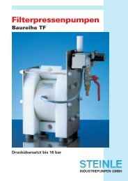
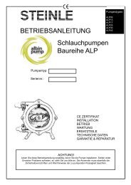
5.1 Performance curves<br />
The performance curves are based on water at 20°C. Other conditions such as higher viscosity and/<br />
or higher specific gravity or higher temperature will change the pump performance.<br />
Example:<br />
Perfomance curve <strong>TF</strong>50/95<br />
A flow rate of 6 m³/h is required and a pressure of<br />
12 should be achieved. A <strong>TF</strong> 100 (100 l/min = 6 m³/h)<br />
is recommended, which has to be supplied with 6 bar<br />
compressed air.<br />
Page 16<br />
When 16 bar should be achieved, the same pump<br />
must have an air supply of 8 bar. A <strong>TF</strong>F 100 is<br />
recommended, when 8 bar air pressure are not<br />
available. In this case only 4 bar air pressure are<br />
suitable.
5<br />
CHAPTER<br />
5.2 Dimensions<br />
G<br />
A<br />
D ruckseite<br />
Saugseite<br />
5.3 Technical data<br />
J<br />
M 8<br />
DATA<br />
Stecknippel<br />
N W 7,8<br />
A B C D E F G H J<br />
<strong>TF</strong> 50 150 166 264 360 245 36 130 140 1/2”<br />
<strong>TF</strong> 95/100 200 220 376 522 320 44 140 154 1”<br />
<strong>TF</strong> 200 270 316 446 652 450 68 210 250 1 1/2”<br />
<strong>TF</strong> 400 350 386 564 802 560 80 290 320 2”<br />
Page 17<br />
C<br />
max. suction lift Solid size Pressure Temperature Weight (kg)<br />
(mWS) max. (mm) max. (bar) max. (°C) <strong>PE</strong> P<strong>TF</strong>E<br />
dry filled <strong>PE</strong> P<strong>TF</strong>E<br />
<strong>TF</strong> 50 3 9 4 16 60 110 5 7<br />
<strong>TF</strong> 95/100 4 9 6 16 60 110 10 17<br />
<strong>TF</strong> 200 5 9 10 12 60 110 24 44<br />
<strong>TF</strong> 400 5 9 15 12 60 110 44 90<br />
H<br />
B<br />
F<br />
E<br />
D
CHAPTER<br />
6<br />
WARRANTY & REPAIR<br />
6.1 Returning parts<br />
When returning parts to STEINLE Industroiepumpen please follow this procedure:<br />
- Consult STEINLE for shipping instructions.<br />
- Cleanse or neutralize and rinse the part/pump. Make sure the part/pump is completely empty<br />
from liquid.<br />
- Pack the return articles carefully to prevent any damage under transport.<br />
Goods will not be accepted unless the above procedure has been complied with.<br />
6.2 Warranty<br />
STEINLE <strong>Industriepumpen</strong> warrants products* of it's own manufacture will be free from defects in raw<br />
material and manufacture under normal use and service for a period of not more than one year.<br />
STEINLE's obligation under this warranty being limited to repair or replacement of its products which<br />
shall be returned to STEINLE Industriepumepn. Follow the procedures above "returning parts". If a<br />
pump or part is received defected, report to STEINLE immediately. Parts returned to our company<br />
must have written authorisation from STEINLE. This warranty will not apply to any of our products<br />
which shall have been used other than for their intended use.<br />
* Even when products such as diaphragm pumps operate under normal conditions, some parts are subject<br />
to wear and may have to be replaced within one year. Examples of such parts in our diaphragm pumps are;<br />
diaphragms, valve balls, o-rings and gaskets etc. This warranty will not apply to these parts being subject<br />
to wear.<br />
Page 18
CHAPTER<br />
6<br />
6.3 Warranty form<br />
Company:<br />
Telephone: Fax:<br />
Address:<br />
Country: Contact name:<br />
E-mail:<br />
Delivery date: Pump was installed (date):<br />
Pump type: Serial No (stamped on the pump housing):<br />
Description of the fault:<br />
The installation<br />
Liquid:<br />
Temperature (°C): Viscosity (cPs): Spec. grav. (kg/m 3 ): pH-value:<br />
Contents of particles: %, of max size (mm):<br />
Flow (l/min): Duty (h/day): No of starts per day:<br />
Discharge head (mwc): Suction head/lift (m):<br />
Air pressure (bar): Quality of the air (filter, micron?, lubrication?):<br />
Other:<br />
WARRANTY & REPAIR<br />
Place for sketch of the installation<br />
Page 19
DISTRIBUTOR:<br />
Page 20<br />
STEINLE Industriepumen - Varnhagenstr. 42<br />
D - 40225 Düsseldorf, Germany<br />
Tel.: ++49-211-33 32 73 Fax: ++49-211-33 07 55<br />
www.steinle-pumpen.de