TF PE englisch - Steinle Industriepumpen GmbH
TF PE englisch - Steinle Industriepumpen GmbH
TF PE englisch - Steinle Industriepumpen GmbH

Create successful ePaper yourself
Turn your PDF publications into a flip-book with our unique Google optimized e-Paper software.
1 INSTALLATION<br />
CHAPTER<br />
1.1 Receiving inspection<br />
Although precaution is taken by us when packing and shipping, we urge you to carefully check the<br />
shipment on receipt. Make sure that all parts and accesories listed on the packing list are accounted<br />
forImmediately report any damage or shortage to the transport company and to STEINLE<br />
<strong>Industriepumpen</strong>.<br />
1.2 Storage<br />
If the equipment is to be stored prior to installation, place it in a clean location. Do not remove the<br />
protective covers from the suction, discharge and air connections which have been fastened to keep<br />
pump internals free of debris. Clean the pump thoroughly before installation.<br />
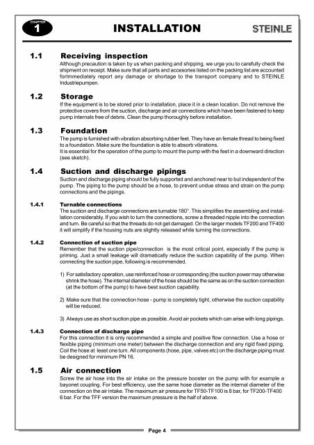
1.3 Foundation<br />
The pump is furnished with vibration absorbing rubber feet. They have an female thread to being fixed<br />
to a foundation. Make sure the foundation is able to absorb vibrations.<br />
It is essential for the operation of the pump to mount the pump with the feet in a downward direction<br />
(see sketch).<br />
1.4 Suction and discharge pipings<br />
Suction and discharge piping should be fully supported and anchored near to but independent of the<br />
pump. The piping to the pump should be a hose, to prevent undue stress and strain on the pump<br />
connections and the pipings.<br />
1.4.1 Turnable connections<br />
The suction and discharge connections are turnable 180°. This simplifies the assembling and installation<br />
considerably. If you wish to turn the connections, screw a threaded nipple into the connection<br />
and turn. Be careful so that the threads do not get damaged. On the larger models <strong>TF</strong>200 and <strong>TF</strong>400<br />
it will simplify if the housing nuts are slightly released while turning the connections.<br />
1.4.2 Connection of suction pipe<br />
Remember that the suction pipe/connection is the most critical point, especially if the pump is<br />
priming. Just a small leakage will dramatically reduce the suction capability of the pump. When<br />
connecting the suction pipe, following is recommended.<br />
1) For satisfactory operation, use reinforced hose or corresponding (the suction power may otherwise<br />
shrink the hose). The internal diameter of the hose should be the same as on the suction connection<br />
(at the bottom of the pump) to have best suction capability.<br />
2) Make sure that the connection hose - pump is completely tight, otherwise the suction capability<br />
will be reduced.<br />
3) Always use as short suction pipe as possible. Avoid air pockets which can arise with long pipings.<br />
1.4.3 Connection of discharge pipe<br />
For this connection it is only recommended a simple and positive flow connection. Use a hose or<br />
flexible piping (minimum one meter) between the discharge connection and any rigid fixed piping.<br />
Coil the hose at least one turn. All components (hose, pipe, valves etc) on the discharge piping must<br />
be designed for minimum PN 16.<br />
1.5 Air connection<br />
Screw the air hose into the air intake on the pressure booster on the pump with for example a<br />
bayonet coupling. For best efficiency, use the same hose diameter as the internal diameter of the<br />
connection on the air intake. The maximum air pressure for <strong>TF</strong>50-<strong>TF</strong>100 is 8 bar, for <strong>TF</strong>200-<strong>TF</strong>400<br />
6 bar. For the <strong>TF</strong>F version the maximum pressure is the half of above.<br />
Page 4