machine building & automation - Industrial Technology Magazine
machine building & automation - Industrial Technology Magazine
machine building & automation - Industrial Technology Magazine
- No tags were found...
You also want an ePaper? Increase the reach of your titles
YUMPU automatically turns print PDFs into web optimized ePapers that Google loves.
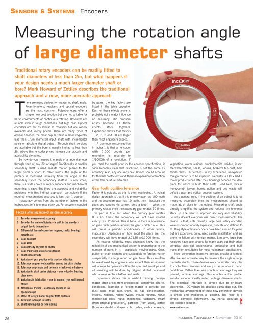
SENSORS & SYSTEMSEncodersMeasuring the rotation angleof large diameter shaftsTraditional rotary encoders can be readily fitted toshaft diameters of less than 2in, but what happens ifyour design needs a much larger diameter shaft orbore? Mark Howard of Zettlex describes the traditionalapproach and a new, more accurate approachThere are many devices for measuring shaft angle.Potentiometers, resolvers and optical encodersare the most common. Potentiometers offer asimple, low cost solution but are not suitable forharsh environments or continuous rotation. Resolvers arereliable even in tough conditions, but high cost. Opticalencoders are not as robust as resolvers but are widelyavailable and keenly priced. There are many types ofoptical encoder; the most popular have a small (typicallyless than 1/2in diameter) input shaft with incrementalpulse or absolute digital output. Through shaft versionsare available but the bore is usually limited to less than2in. Above this, encoder prices increase dramatically andavailability dwindles.So how do you measure the angle of a large diameterthrough shaft of, say, 3in or larger? Traditionally, a smallersecondary shaft is used and its motion geared to thelarger primary shaft. In other words, the angle of theprimary is measured indirectly from the angle of thesecondary. Since the secondary shaft is usually small,there is a wide choice of rotary encoders and mechanicalmounting is easy. But there are accuracy and reliabilityproblems with this indirect approach, particularly if therequired measurement accuracy is less than 1 degree.Inaccuracy comes from the number of factors in theindirect system’s tolerance stack up. For a system coupledFactors affecting indirect system accuracy1. Encoder measurement accuracy2. Encoder thermal coefficients – ie drift in the encoder’soutput due to temperature3. Differential thermal expansion in gears, shafts, bearings,mounts, etc4. Gear backlash5. Gear Wear6. Concentricity of gears on shafts7. Gear train/tooth strain versus torque8. Shaft concentricity9. Variation of gear position with shock or vibration10. Tolerance on gear tooth position around the pitch circles11. Tolerance on primary and secondary shaft centre distance12. Variation in shaft centre distance – due to load or bearingclearances13. Variations in lubrication – due to amount, type and thermaleffects14. Mechanical friction – especially stiction at lowspeeds/torque15. Effect of foreign matter on gear teeth surfaces16. Twist due to torque in shafts17. Shaft bending due to side loadingby gears, the key factors arelisted in the table opposite.Each of these effects alone isprobably not a major influenceon accuracy. The problemarises because all theseeffects stack together.Experience shows that factors1, 2, 3, 5 and 10 are largerthan most engineers expect.A common misconceptionin factor 1 is that an encoderwith 1,000 counts perrevolution is accurate to1/1000th of a revolution. Ifyou read the small print in the encoder specification, itsoon becomes clear that resolution is not the same asaccuracy. Also, any accuracy calculations should accountfor thermal coefficients and thermal expansion/contractionat the temperature extremes.Gear tooth position toleranceFactor 9 is notable, as this is often overlooked. A typicaldesign approach is that if the primary gear has 100 teethand the secondary gear has 10 teeth, then – because thegears are coupled (ie cannot jump a tooth) – when theprimary rotates once the secondary gear rotates 10 times.This part is true, but when the primary gear rotates0.37125 times, the secondary will not have rotatedexactly 3.7125 times. This is because there is a toleranceon gear teeth position around the gear’s pitch circle. Thiswill cause a periodic non-linearity. In other words,inaccuracy. Depending on how good the gears are, thesecondary will have rotated 3.7125 ±0.1000 times.As regards reliability, most engineers know that thereliability of any mechanical system is proportional to thenumber of parts in it – especially moving parts. Gear,pulley or chain systems are susceptible to foreign matter– especially in a large reduction gear train. This can oftenbe overlooked by engineers who expect their equipmentwill always be operated within the specified envelope andall servicing will be done by diligent, skilled personnelwho always replace baffles and seals.Experience shows this is wishful thinking. Foreignmatter often arises from unexpected, sometimes bizarre,conditions. Examples of foreign matter to consider aredust, sand, mud, rain, snow, ice, hail, condensation,insects, rodents, rodent waste, mould, fungus, roguemechanical tools, rogue mechanical fasteners, swarf(from original production), particles (from wear), coffee(from accidental spillage), cola, pollen, air-borne seeds,vegetation, water residue, smoke/cordite residue, insectfaeces/secretions, snails, worms, brake/clutch dust, hair,textile fibres. Far fetched? In my experience, unexpectedforeign matter is to be expected. Recently, a CCTV had amajor product recall after their housings became the idealplace for wasps to build their nests. Dead bees, bits ofhoneycomb, larvae, honey, pollen and bee waste willdefeat a gear and optical encoder system.As a general rule, if the position of an object is to bemeasured accurately then the measurement should bemade at, or close to, the object. Measuring shaft angledirectly simplifies the system and reduces the tolerancestack up. The result is improved accuracy and reliability.So why doesn’t everyone use direct measurement? Thereason is that, until recently, large bore rotary encoderswere disproportionately expensive, delicate and difficult tofit. Ring style optical encoders have been around for yearsbut are expensive, bulky, need careful installation and areprone to failure with foreign matter. Similarly, large boreresolvers have been around for many years but their price,complex electrical supply/signal processing and bulkmake them unsuitable for most mainstream applications.New generation inductive devices enable a simple,effective and accurate way to measure the angle of largediameter shafts. These devices work on similar principlesto contactless resolvers and are just as reliable in harshconditions. Rather than wire spools or windings they useprinted, laminar windings. This enables a low profile,annular encoder ideally suited to large diameter shafts.The electrical interface is simple due to on-boardelectronics – DC voltage in; absolute digital data out. Themechanical arrangement of these new generation devicesis simple and eradicates all gearing. The result is asimple, compact, lightweight, low inertia, accurateand reliable solution.www.zettlex.com26INDUSTRIAL TECHNOLOGY • November 2010


