underground storage tank practices and techniques: underground ...
underground storage tank practices and techniques: underground ...
underground storage tank practices and techniques: underground ...

You also want an ePaper? Increase the reach of your titles
YUMPU automatically turns print PDFs into web optimized ePapers that Google loves.
.?ITECHNIG2!UES FrNr) FRI?=%CT ICESFOR MAN#=bGING UN9ERGRClUNT)I3TQRt=+GETANKS-, I< ,“_ .,l...,__
. I/ZIYT-ECHNIGZUES CaNI PRClrCTICESFOR M6%NClrGING UNDERGROUNL)STClRi=bGET&NKSI .Weaver III, L. AlbertTECHNIQUES AND PRCSCTICES FOR MANAGING UNDERGROUND STORAGE TANKSrn”I,,First Edition 1986c 1986 by L. A. Weaver Company04411 rights reserved. No part of this publication may bereproduced in any form9 stored in a retrieval system, ortransmitted, in any form or by any means, electronic, mechanical,photocopying, recording, or otherwise, without the prior wlrittenpermission of the pub1 i sher,
3,),’IJ :!,,B. Permanent Closure..................................2IX. CONSENSUS STANDARDSA. American Petroleum Institute (API)Recommendations for Underground Storage Tanks.....1B. Underwriters Laboratories--1316Glass-Fiber-Reinforced Plastic Underground StorageStorage Tanks for Petroleum Products..............4C. Underwriters Laboratories--58 Steel UndergroundTank for Flammable <strong>and</strong> Combustible Liquids........6D. ASTM St<strong>and</strong>ard Specification forGlass-Fiber-Reinforced Polyester UndergroundPetroleum Storage Tanks...........................8E. National Fire Proctection Association--30Installation of Underground Tanks................10F. National Fire Protection Association St<strong>and</strong>ardProcedures For Cleaning or Safeguarding SmallTanks <strong>and</strong> Containers.............................1 4G. NFPA Fire Proctection H<strong>and</strong>book...................1 5X. CORROSION THEORYA. Deterioration <strong>and</strong> Corrosion ..................... ..l8. Theory of Corrosion ............................. ..lC. Factors Influencing Corrosion of Metals ........ ...2D. Metals Affected By Corrosion ................... ...4E. Types of Corrosion ............................. ...6F. Corrosive Environments ......................... ...9XI. RCRA TANK REQUIREMENTSA. Design of Tanks ................................. ..lB. Inspections .................................... ...2C. Closure ........................................ ...3D. Special Requirements for Ignitable or Recatives . ..3E. Special Requirements for Incompatible Waste .... ...3F. Special Requirements for Certain Hazardous Waste ..4G. Tanks .......................................... ...4H. General Operating Requirements ................. ...4I. Waste Analysis <strong>and</strong> Trial Tests .................. ..SJ. Inspections ..................................... ..SK. Closure ........................................ ...5L. Specific Part B Information Requirements ....... ...6I a.XII.XIII.CONGRESSIONAL HOUSE RECORDA. Notification <strong>and</strong> Certification .................. ..lB. Release Detection, Prevention, <strong>and</strong> Correction ... ..lC. Approval of State Programs ..................... ...2D. Inspections, Monitoring <strong>and</strong> Testing ............ ...2E. Federal Enforcement ............................ ...2F. Federal Facilities ............................. ...3G. State Authority ................................ ...3H. Key Definitions ................................ ...3I. Studies ........................................ ...4UNDERGROUND STORAGE TANK SERVICES
XI.APPENDICESA. Confined Space Entry ProcedureB. Flammable <strong>and</strong> Combustible LiquidsC. EPA Notification FormD. EPA Contract Report on Spill ReleasesE. EPA Proposed Regulations for UndergroundStorage Tanks
The following chapter-by-chapter summary provides an overview ofthe material contained in this manual. Some of the chapters canpossibly be read as separate units; however, to obtain thegreatest benefit from the manual r the entire manual should firstbe read especially before attempting to apply any of the remediespresented.Many of the environmental <strong>and</strong> economic issues concerning leaking<strong>underground</strong> <strong>storage</strong> <strong>tank</strong>s in the United States3 including vitalstatistical information on the costs <strong>and</strong> methods of cleanup:, whereleaks occur <strong>and</strong> how to avoid them:, <strong>and</strong> current regulations arediscussed in Chapter I. This chapter also discusses specialproblems of <strong>underground</strong> <strong>storage</strong> <strong>tank</strong>s such as groundwatercontamination) <strong>and</strong> corrosion.Chapter I I deals with the legislation concerning <strong>underground</strong><strong>storage</strong> <strong>tank</strong>s. This chapter defines regulated substances3 owners<strong>and</strong> operators, <strong>and</strong> releases. chapter II also lists the piarts ofthe five RCKA provisions including interim prohibition3 thenotif ication program, the regulatory programs the state program7<strong>and</strong> the inspect ion <strong>and</strong> enforcement program. This chapter alsolists which <strong>tank</strong>s are excluded from regulation.Chapter I I I presents the methods <strong>and</strong> prodedures for <strong>underground</strong><strong>tank</strong>: instal lat ion. The areas addressed in chapter III includesite selection <strong>and</strong> its preparation7 excavation size <strong>and</strong> depth rdewater ing proceduresY testing <strong>and</strong> inspection prior toinstallation9 h<strong>and</strong>ling:. bedding <strong>and</strong> backfill for fiberglass <strong>and</strong>steel <strong>tank</strong>s? dry hole-wet hole installationsP anchoring7 pavementopenings <strong>and</strong> cover y <strong>and</strong> finally post-installation testing <strong>and</strong>inspection. Included in the discussions are the recommendedvalues needed for each application.Corrosion control:. which is a major factor in controlling <strong>tank</strong>:leaks is the focus of chapter IV. This chapter discusses howcorrosion occurs <strong>and</strong> how to protect against it ‘through methods ofinternal <strong>and</strong> external corrosion protection. Interior protectionconsists primarily of protective films, lining <strong>and</strong> coating!, <strong>and</strong>fill pipe protection. Exterior protection is accomplished by acombination of exterior coating for steel <strong>tank</strong>s? <strong>and</strong> cathodicprotection. The use of fiber-glass-reinforced plastic <strong>tank</strong>s isa 1 so d i scussed .Chapter V overviews the methods <strong>and</strong> procedures fur testing<strong>underground</strong> <strong>storage</strong> <strong>tank</strong>s <strong>and</strong> piping systems for lea!::s. The <strong>tank</strong>::test methods include pneumatic testing:, hydrostatic- HeathPetro-tite? J-tube manometer) Sunmack leak detector z laser-beam?<strong>and</strong> Arco HTC detection systems. Pipe1 ine testing proceduresinclude suction piping tests <strong>and</strong> discharge 1 ine test. Alao Ldiscussed in this chapter are methods of inspection <strong>and</strong> checkingfor water in <strong>tank</strong>s.PREFACE1
The methods involved in leak detection are reviewed in chapter VI.This chapter includes sections on early warning leak detectionsysteki 9 area wide surveillance, recovery we1 ls;r overf i 11prevention systems, <strong>and</strong> transfer spill prevention systems. Thekey factors of each system or method along with a description ofthe necessary sensing devices are included.The various materials <strong>and</strong> methods used for lining <strong>underground</strong><strong>storage</strong> <strong>tank</strong> systems, to prevent the spread of leaking materialare important considerations in managing <strong>underground</strong> <strong>storage</strong><strong>tank</strong>s. Factors such as compatibilityY environmental, <strong>and</strong>legislative ccbncerns are discussed!, together with the use<strong>and</strong> instal lat ion of various containment materials such asclay 1 iners;, synthetic membrane 1 inersY soi 1 sealants? corrcretevaults-s:, <strong>and</strong> double-walled <strong>tank</strong>s. These issues are reviewed inchapter VI I.Chapter VI II concerns the ab<strong>and</strong>onment <strong>and</strong> removal procedures for<strong>underground</strong> starage <strong>tank</strong>s. These procedures are necessary toprevent envirunmental <strong>and</strong> health prublemss <strong>and</strong> accidents fromincompati,ble materials7 <strong>and</strong> intrusion. The three primarymanagement captions discussed in this chapter include temporaryc losure) ab<strong>and</strong>ctnmen t in p 1 ace Y <strong>and</strong> removal for reuse or disposal.Chapter IX discusses the consensus st<strong>and</strong>ards far <strong>underground</strong><strong>storage</strong> <strong>tank</strong>s as set forth by the American Petroleum Institute(API)s Underwriters Labaratories (UL) !, American Society forTesting <strong>and</strong> Materials (ASTM) !, <strong>and</strong> the National Fire ProtectionAssociation (NFF’A). These st<strong>and</strong>ards cover many aspects of<strong>underground</strong> <strong>storage</strong> <strong>tank</strong>s P from construction <strong>and</strong> installation toab<strong>and</strong>onment <strong>and</strong> disposal .Chapter X presents an overview of the mechanisms by whichcc~rrc~sian occurs <strong>and</strong> the metals mast susceptible to cclrrosiveattack. The theory of corrasian is detailed in this chapter. Allunderst<strong>and</strong>ing of the material presented will aid in underst<strong>and</strong>ingthe st<strong>and</strong>ards <strong>and</strong> safe <strong>practices</strong> presented in other chapters.The RCRA <strong>tank</strong> requirements that exist prior to the promulgation ufrules <strong>and</strong> regulations specifically far <strong>underground</strong> <strong>storage</strong> <strong>tank</strong>sare presented in Chapter XI. These are from the federal RCRAst<strong>and</strong>ards that were in effect as of March 1986. There may bestate st<strong>and</strong>ards that are also effective. To be sure7 check: withthe appropriate state agency for coverage.Chapter XII includes information from the Congressional RecordPart II-NC
proper entry. The second appendix provides an clvervi-ew offlammable <strong>and</strong> combustible liquids. Since many of the materialscontained in an <strong>underground</strong> <strong>storage</strong> <strong>tank</strong> are either flammable orcambustible, an appreciation of the risks <strong>and</strong> classification offlammables <strong>and</strong> combustibles is essential. The third areapresented in the appendices is the EPA notification form forundergrcaund <strong>storage</strong> <strong>tank</strong>s. Notice that the form, NOTIFIC:ATION FORUNDERGROUND STORAGE TANKS, is a North Carolina form. Individualsis other states should consult with EPA to determine who theenforcing authority is in a given state tu secure th appropriateform.PREFACE3
I, EN’VIRONMENTAL f=+NL) ECONOMICISSUESSPECIAL PROBLEMS OF UNDERGROUND STORAGE TANKSGroundwater contamination is a major environmental issue of the1930s ‘I said the Environmental Protection Agency (EPA>. Anestimated 117 million Americans -- more than half the nation’spopulation -- could be affected by chemicals leaking into thenation’s water supply. More than half of the country depends ongroundwater for drinking. The other half relies on surfacewater. About 95 percent of al 1 rural households use groundwater.Leaking <strong>underground</strong> <strong>storage</strong> tan1::s is a major source ofgroundwater contamination. More than 200 substances have beendetected in groundwater. An estimated 29 percent of the drinkingwater supplied from groundwater to large cities is contaminatedwith volatile organic chemicals. These <strong>tank</strong>s store a range ofliquids7 including gasol i ne, hazardous <strong>and</strong> toxic chemicals,,fuels7 process chemicals <strong>and</strong> diluted wastes. There are anestimated 2.5 - 5 million <strong>underground</strong> <strong>tank</strong>s in the United States.As many as half contain gasoline.Lighter products? such as gasoline, can travel more quick:lythrough the soil than heavier substances, making them moredifficult to recover initially. Cleanup at l<strong>and</strong> surface can besimple <strong>and</strong> effective, but once the spill moves into thesubsurf ace Y recovery is more difficult <strong>and</strong> expensive, Qui c 1:: work::can prevent groundwater contamination. While about half of thewater systems drawing from groundwater provide chlorinationtreatments, this is ineffective for chemical contaminants.Internal <strong>and</strong> external corrosion, punctures or cracks? ages soilconditions <strong>and</strong> improper installation -- any of these can resultin a leaking <strong>tank</strong>. But corrosion is the major factor contributingto leaks in steel <strong>tank</strong>s. A fraction of the more than two million<strong>underground</strong> gasoline <strong>storage</strong> <strong>tank</strong> systems are constructed ofcathodically protected steel or fiberglass. Most <strong>tank</strong>s areunprotected steel <strong>tank</strong>s3 highly susceptible to corrosion.The typical design life is 15-X) years. New <strong>tank</strong>s are designedfor corrosion resistance <strong>and</strong> are made of fiberglass or havedouble liners. However F an estimated one mi 11 ion <strong>underground</strong><strong>tank</strong>s are more than 16 years old.Underground leakage is essentially a shallow groundwater problem.The spilled substances immediately saturate the soil. Thehydrogeologic characteristics at the spill site need to beexamined in order to determine the route the spill wi 11 take whenit reaches the water table. In many cases, the spilled pr-oductflows in the direction of least resistance. The water tablefollows the same direction as the topography. - Groundwater movessl owl y -- from 5 to 50 feet per year, by some estimates. Sincecontaminants move in fan-like directions, there is little1ENVIRONMENTAL AND ECONOMIC ISSUES I:
i\ i
dispersion. It is important to underst<strong>and</strong> that hazardous 1 iquidsdo not biodegrade or decompose. Chemical or biological chiangesoccur 51 owl y . Volumes of contaminants can enter groundwater <strong>and</strong>go unnoticed for years. When a substance leaks <strong>underground</strong>, itwill be a hazard until it is removed.If the average leaking <strong>underground</strong> <strong>storage</strong> <strong>tank</strong> leaks one gallonper day I 100, 000 tanlr:s
are connected electrically, <strong>and</strong> a consequent I ass of metal ionsat the anode area results in ccwrQsicm.Fiberglass <strong>storage</strong> <strong>tank</strong>s are a popular solution because they areessentially corrosion-proof <strong>and</strong> require little maintenance.I-bWeVer 7 they can crack, if not installed properly. Fiberglass<strong>tank</strong>s cannot prevent the problem af leaks that occur in piping.An estimated 60 percent of <strong>underground</strong> leaks occur in pip:i ng.Leaks in piping can be a problem even with double-walled <strong>tank</strong>installations. There is no protection where the pipe meets the<strong>tank</strong> <strong>and</strong> where the pipe curves to form an elbow. Double wallprotection is not as common as liner protection because of theabsence of protection at vital joints. A liner covers all areas?assuring better protection at the joints <strong>and</strong> less leakagE.Some companies are installing secondary containment systems.There feature flexible, chemically resistant liners. The!se 1 i nersprovide a backup to cantain chemical leakage until the system canbe repaired or replaced.C. RE6ULATIOiISLeaking <strong>underground</strong> <strong>storage</strong> <strong>tank</strong>s are dif f i ct~l t for regulatoryagencies to control. Toxic waste dumps are usually concentratedin a 5pecific place. Underground <strong>storage</strong> <strong>tank</strong>s can be anywhere.Some are in use -- others ab<strong>and</strong>oned.To date, few state <strong>and</strong> local governments have confronted theissue of leaking <strong>underground</strong> <strong>storage</strong> <strong>tank</strong> systems. New York <strong>and</strong>California are the only two states requiring secondarycontainment.The EPA has established guidelines giving state <strong>and</strong> localauthorities a basis +or regulating <strong>tank</strong> installation, monitoring<strong>tank</strong> safety, <strong>and</strong> when necessary, assessing pal luters for thecleanup of damaged water supplies.When an <strong>underground</strong> leakage is detected or reported, consult ahydrogeologist, or ground-water special iot. Recovery programs maybe complex <strong>and</strong> time-consuming. It is best to seek expert help atthe beginning.-7“..~ .JENVIRONMENTAL AND ECONOMIC ISSUESI
II, LEGISLcrrlTXCJN f=%NI) UNDERGROUNr)S-l-OReGE,TIlrN)c=STHREAT OF GROUNDWATER CONTAMINATION PROMPTS NEW LAWA. HISTORY OF THE LEGISLATIMIRecent Leaking Underground Storage Tank (LUST1 legislation greatlyaffects <strong>tank</strong>: regulation. On November 8, 1984, President F?eagansigned the “Hazardous <strong>and</strong> Solid Waste Amendments of 1984. “ Thenew laws will become effective during a six-year period thatbegan in May, 1985.In 1983, a Senate subcommittee discussed groundwatercontamination <strong>and</strong> leaking <strong>underground</strong> <strong>storage</strong> <strong>tank</strong>s as a primarysource of environmental <strong>and</strong> economic damage, Hy some estimations,more than 3.5 million buried <strong>tank</strong>s may exist. The <strong>tank</strong>s mlaycontain carcinoaene materials or volatil hat could e>:pl ode attP=urfassaturatedsoi 1. Fuel is the most common ofcontained substances with by-products of the chemical industry aclose second. Drqanic cleaning solvents routinely used inmanufacturing are also stored in <strong>tank</strong>s.The Environmental Protection Agency (EPA1 estimates 1CK),CK~C~ <strong>tank</strong>sare leaking <strong>and</strong> another 350,000 are expected to leak in the nextfive years. The American Petroleum Institute said 40 percent. to75 percent of al 1 <strong>underground</strong> <strong>tank</strong>s are leaking now or will beshortly.EPA’s LUST program m<strong>and</strong>ates:(B A mas5ive <strong>tank</strong> registration programQ) Federal technical st<strong>and</strong>ards for new <strong>and</strong> existing <strong>tank</strong>s5 State LUST programs <strong>and</strong> grants@ Federal inspection <strong>and</strong> enforcementCB! Studies <strong>and</strong> reports to CongressLegislation relating to leaking <strong>underground</strong> <strong>tank</strong>s is coming fromall government levels, including local, state <strong>and</strong> feder_al.Industry will be regulated at evercaste disposal phase, fromthe <strong>tank</strong> installation to the discovery of contamination,BJNDERfiROUND STORAGE TANKS DEFINEDA "regulated substance" is defined in two sections:1. Any substance defined in section 101(14) of the ComprehensiveEnvironmental Response, Compensation, <strong>and</strong> Liability Act of 1980(but not including any substance regulated as a hazardous wasteunder subtitle G).2, Petroleum, including crude oil or any fraction thereof whichis liquid at st<strong>and</strong>ard conditions of temperature <strong>and</strong> pressure (601LEGISLATION AND UNDERGROUND STORAGE TANKS II_ _, _. . _ - -.:-
.- . . ., ._-degrees Fahrenheit <strong>and</strong> 14.7 pounds per square inch absol ut.el .1. OWNERS AND OPERATORSAn <strong>underground</strong> <strong>storage</strong> <strong>tank</strong> wner is legally defined as aryer son who owns an undersround <strong>storage</strong> <strong>tank</strong> used for the<strong>storage</strong>Luse, or diswnsinq of requlated substances9 <strong>and</strong> anyperson who owned s;kx <strong>tank</strong> immediately before the discontinuationof it5 use.An operator is described as a oerson in control of, or havingresponsibility for, the daily operation of the <strong>underground</strong><strong>storage</strong> <strong>tank</strong>.The owner <strong>and</strong> operator are generally separate entities whenreferring to petroleum <strong>tank</strong>s. In an industrial environment, theowner <strong>and</strong> operator are usually in the same corporation.2. RELEASESRe_lease refers to any spilling, leaking, emittinq, discharqinq,escaping? 1 each-r rfl‘-pn=~ . - “‘IFfrom an ~lnrlernround <strong>storage</strong> <strong>tank</strong>:into groundwater 5 surf ace water or subsurf ace soi Is.RCRA SUBTITLE ISubtitle I under RCRA has five provisions that deal withUnderground Storage Tanks. The provisions have similar areas ofresponsi bi 1 i ty <strong>and</strong> authority. RCRA’s Underground Storage Tank:(UST) Frogram provides an in&x.,im Prohibition on theinstallation of <strong>underground</strong> <strong>storage</strong> <strong>tank</strong>s for petroleum <strong>and</strong>hazardous products, unless the <strong>tank</strong>s meet ‘certain requirements.Second 7 the program implements a nationwide notif ication programfor existing <strong>tank</strong>s. This affects thous<strong>and</strong>s of <strong>tank</strong> owner&-Z%-distributors across the country as well as the sellers ofregulated products. Third, the program provides a regulatoryprogram for the development of performance st<strong>and</strong>ards for new<strong>tank</strong>s. Fourth, the UST Program permits authorized stateprograms to operate in lieu of the federal regulations. EZachstate program must be as stringent as the federal program.: Theprogram provides for the inspection of <strong>tank</strong>s <strong>and</strong> enforcementof these federal st<strong>and</strong>ards.The entire <strong>underground</strong> <strong>storage</strong> <strong>tank</strong>: program is unique to EEFA inthat it deals with stored product <strong>and</strong> not only regulated wastes.1. INTERIM PROHIBITIONThe first area is a pv the a=+allation of <strong>tank</strong>=that do npt meet certain minimum requirements. The Prohibitionstipulates that all tanC::s newly placed in the ground <strong>and</strong>intended to contain petroleum <strong>and</strong> other hazardous materialsmust be designed, constructed, <strong>and</strong> installed to prevent leaks,.= .1LEGISLATION AND UNDERGROUND STORAGE TANKS II2
N@000person may i nstall an LIST unless:The <strong>tank</strong> will prevent of the stored substances due tocorrosi.on or structural failure for the operational life of a<strong>tank</strong>The <strong>tank</strong> is cathodically protected agmion; ordesigned to pr or threatening release .,of the‘-stgred substances orThe material used in the construction of the <strong>tank</strong> is compatible-stance to be storedThe prohibition also covers old <strong>tank</strong>s which are newly installed.Only exception to the Interim Prohibition on installing <strong>tank</strong>swithout corrosion protection is where soil is noncorrosive.Penalty for non-compliance to the provision is a fine of up to810,000 per day per <strong>tank</strong>.The Interim Prohibition was effective May 7, lS85 <strong>and</strong> will remainin effect until new <strong>tank</strong> st<strong>and</strong>ards are issued. The EPA expectsthese st<strong>and</strong>ards in 1987.2. NOTIFICATION PHQGRWIThe new RCRk calls for a notification program which affectedthous<strong>and</strong>s of <strong>tank</strong> owners. It requires actions by distributorsof regulated substances, sellers of <strong>tank</strong>s, <strong>and</strong> owners of <strong>tank</strong>staken out of operation within the past 10 years but still in theground V as well a5 owners of operational <strong>tank</strong>s.The designated state or local agency is to receive notification<strong>and</strong> not the EPA.Implementationschedule:o May 1985, state governors designated state agencies to receive.notifications.o On November 8, 1985, EPA promulgated notification forms which -require infomation on the ages size, type, location, <strong>and</strong> usesof <strong>tank</strong>sa From December 8F 1983 through June 8, 1987, any. person whodeposits regulated substances in an <strong>underground</strong> <strong>storage</strong> <strong>tank</strong>must inform the <strong>tank</strong> owner of the requirements to notify thestate agencyo By May EJ9 1986,, owners of existing UST had to submitnotification forms to the appropriate state agencyo By May 8, 1986, owners of UST taken out of operation afterJanuary lt 1974, but still in the ground? had to submitnotification formso Since May 1986, owners of newly installed UST must notify thestate agency within 30 days after bringing the <strong>tank</strong> into useo In 1987, EPA expects to issue new <strong>tank</strong> regulationsLEGISLATION AND UNDERGROUND STORAGE TANKS II
Thirty (30! days after EPA issues new <strong>tank</strong>: performance st<strong>and</strong>ardsse1 lers c:f <strong>underground</strong> <strong>storage</strong> <strong>tank</strong>s must inf arm purchasersof the notification requirements.EPA published notification forms along with names of stateagencies designated to receive them in the November 8, 198:sFederal Register.T3 . REGULATORY PROGRAMEPA must develop <strong>and</strong> promulgate performance st<strong>and</strong>ards for new<strong>tank</strong>s, including but not limited to design, construction,installation, release detection, <strong>and</strong> compatability.Regulations require owners <strong>and</strong> operators to:- have methods for detecting releases- keep records of the methods- take corrective action in response to relea5e5- report releases <strong>and</strong> corrective actions taC::en- provide for taking <strong>tank</strong>s out of service- provide evidence of financial responsibility for correctiveacti on takenSt<strong>and</strong>ards for new <strong>tank</strong>s <strong>and</strong> regulations concerning leakdetection/prevention <strong>and</strong> corrective action for petroleum isexpected by February l?S? <strong>and</strong> August 1987 for hazardous.chemicals.4. STATE PROGRAMBy May 1987, states may apply to EPA for authorization to operatean UST program. State programs must include all the regulatoryelements of the federal program <strong>and</strong> proi/ide for adequateenforcement. After a 1 to 3 year grace period, state requirementsmust be “no 1 es5 stringent” than federal requirements.5. INSPECZTION AND ENFOHCEMENTOffenders are subjected to civil penalties to up to $l(:),OOO per<strong>tank</strong> each day of non-compliance.TanI::s excluded from the statute are:- farm or residential <strong>tank</strong>s of l,lCK) gallons or less capacityused for storing motor fuel for noncommercial purposes- <strong>tank</strong>s used for storing heating oil for consumptive use on thepremises where stored- septic <strong>tank</strong>s- pipelines (including gathering lines) regulated under- the Natural Gas Pipel.ine Safety Act of 1968 (49 U.S.C. App.1671, et seq. 1 the Hazardous Liquid Pipeline Safety Act of1979 (49 U.S.C. App. 2061, et seq.), or an intrastatepipeline facility regulated under state laws. ” .,~4LEGISLATION AND UNDERGHOUND STORAGE TANKS II
- surface impoundment, pit, pond, or lagoon- storm. water ar waste water ccrllection syc.tem- flow-through precess <strong>tank</strong>- liquid trap or ar;saciated gathering lines directly relatedto oil or gas production <strong>and</strong> gathering operations, or<strong>storage</strong> <strong>tank</strong> situated in an <strong>underground</strong> area !such arj abasement, cellar5 mineworking, drift, shaft, or tunnel) ifthe <strong>storage</strong> <strong>tank</strong> is situated upon or above the surfacc2 elf thefloorLEGISLATION AND UNDERGROUND STORAGE TANKS II
j ra!SI--iil.ri,-t!^i3I.95a.3ID9.
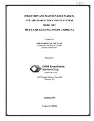
III, -r#=aNK INSl-CSl-t#=%TIONMETHODS AND PROCEDURESPoor installation <strong>and</strong> mish<strong>and</strong>ling of <strong>storage</strong> <strong>tank</strong>s <strong>and</strong> equipmentbefore installation can result in leaks. Avoiding this possibilityfrom the outset can reduce the chances of leakage <strong>and</strong> costlycleanup. The most prevalent installation errors’ include:o damage to protective coatings of steel <strong>tank</strong>so use of corrosive backfill materials (both or either mistake canlead to accelerated corrosion.of <strong>underground</strong> steel <strong>tank</strong>s)o structural damage to <strong>tank</strong> materials during transportation<strong>and</strong> installationo poor <strong>tank</strong> anchoring in high groundwater areaso poor foundations, lack of bedding, or improper compactionof backfillFailure to properly level a <strong>tank</strong> during installation can lead tocreation of air pockets in the <strong>tank</strong> during its use, preventingaccurate measurement of inventory losses <strong>and</strong> <strong>tank</strong> leaks.Poor <strong>tank</strong> installation can lead to <strong>tank</strong> settling, <strong>tank</strong> floatation,or deflection of <strong>tank</strong>s -- any of which can result in damage to<strong>tank</strong> or piping.Major <strong>tank</strong> manufacturers warrant their <strong>tank</strong>s against failure onlyif they are installed <strong>and</strong> used in accordance with manufacturer”5instructions.A. SITE SELECTIOMMany <strong>storage</strong> problems are due to poor site conditions <strong>and</strong>incorrect design. The American Petroleum Institute (API)Publication 1615, Installation of Underground Petroleum StorageSystems, is a guide for engineers, marketers <strong>and</strong> contractors inthe design of <strong>underground</strong> gasoline service station systems. Otherhelpful st<strong>and</strong>ards regarding installation include NFPA 30 (19) <strong>and</strong>the New York Sate Department of Environmental Conservation(NYS-DEC) manual. This manual covers st<strong>and</strong>ards for bulk <strong>storage</strong> ofhazardous liquids.B. PREPARING THE INSlALLATION SUEUnderground <strong>tank</strong>s must be located outside the bearing pressureof structural footings so as not to receive foundation loads.Tanks should be located no closer than 10 feet to a building toavoid footing pressures, undermine existing structure foundations<strong>and</strong> other construction problems.API installation requirements identify <strong>tank</strong> clearance,excavation depth, <strong>and</strong> anchoring <strong>and</strong> backfilling requirements.General examples include:INSTALLATION1III
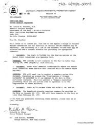
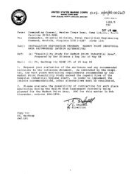
ELEtlENTS DF AN UNDERGROUND STORAGE T&NK INSTALLATIONflUERCTl I PREUCUT~~N DEVICEVAPORECOVERY LINEEXCAVATION x k%PEA BRAVEL 4OR SAND FILLI/;;H-’ L PRODUCT DELIVERY L.INEAUTOnkTICSHUTOFFVALVEEWGTMN HALLS AND - SUiREROED PUHP MSEHBLYFLOORS OF IHPERVIOUS MTERIAL
a at least six inches; <strong>and</strong> 12 inches in all horizontaldirectionso a minimum <strong>tank</strong> clearance of 12 inches in all horizontaldirections0 in areas not subject to traffic, cover depth should be aminimum of 24 inches, or not less than 12 inches plus areinforced concrete slab not less than four inches inthicknesso where <strong>tank</strong>s are subject to traffic, cover depths are aminimum of 36 i nchesj, or not less than 18 inches of well-tampedmaterial plus at least six inches of reinforced concrete oreight inches of asphaltic concrete1. EXCAVATION SIZEThe excavation should be large enough for the <strong>tank</strong> plus a minimum:clearance of 24 inches between adjacent <strong>tank</strong>s, <strong>and</strong> between <strong>tank</strong>sides <strong>and</strong> ends <strong>and</strong> the banks of a hole. This is for stable soilsituations where shoring is not required to maintain a verticalwall from top to bottom. The space wi 11 be large enough. to al lowtamping of backfill <strong>and</strong> to properly cushion the <strong>tank</strong>.In unstable soi 1 I, muck, peat or dry s<strong>and</strong>, a ho1 e equal to 1 1.12the diameter of the <strong>tank</strong> being installed is usually necess.ary.2. EXCAVATION DEPTHTank burial depth depends on:.* L,/.,*,=,. .a.,V,“.,_i. _o type of <strong>tank</strong> (steel, fiberglass reinforced, etc. 10 local regulationso type of finished surface to be applieda soil conditionso topography0 suction pumping lift requirementThe excavation depth is generally equal to the minimum depthplus one <strong>tank</strong> diameter.For atmospheric <strong>tank</strong>s of steel construction, <strong>tank</strong>s may be burieddeeper but in no case should the burial depth be such that thestatic head imposed on the bottom of the <strong>tank</strong> exceeds 10 psig withthe fill pipe or vent pipes filled with liquid, unless the <strong>tank</strong> isdesigned for higher pressure service.Atmospheric <strong>tank</strong>s of fiberglass reinforced plastic constructionmay also be buried deeper but the depth of cover must not exceed84 inches (7 feet) over the <strong>tank</strong> top.’7.J . DEWATERING THE EXCAVATIONDewatering may be necessary in areas of high groundwater or wheresurface runoff leads to accumulations of water in the excavation,j ,* 2INSTALLATIONIII
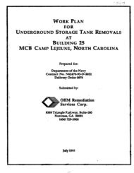
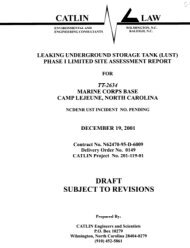
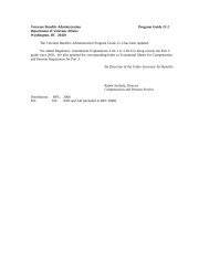
PRE-ENGINEERED UNDERGROUND STORME TANKVENT LINEDIELECTRIC BUSHINGS / /FLOAT VENT VALVEPRODUCT DELIVERY LINE ACCESS MNMYALEAK DETECTOR ONMTHODICALLY-PROTECTED,EPOXY COATED STEEL TANKSTRIKER PLATEIcHONITORIN6 HETERSACRIFICIALWELLCOt!PAClED BED OF,SAND OR 6RlVEL
duringinstallation.Cne or a combination of these methods can be used to dewater a5i te:i . Water can be al lowed to flow into an excavation <strong>and</strong> pumpedout from sumps or ditchesii. The water table can be lowered before excavating, usingeither wells, wellpoints or ejectorsiii. Cutoff walls of slurry or grout can be installedFactors influencing the choice of a dewatering procedure,ekcluding cost, are:a nature of the soilo area groundwater hydra1 ogyo size <strong>and</strong> depth of the excavationo proposed method of excavation <strong>and</strong>, if necessary, wallsupporto proximity of existing structureo construction schedule or required duration of dewateringoperationsC. TESTINB AND INBPECTION -- PREINSTKLBTIDNIt is recommended that all <strong>tank</strong>s be tested before shipment. Whenthe <strong>tank</strong> arrives? it is recommended that the <strong>tank</strong> be cleaned ofdirt clods, visual ly inspected <strong>and</strong> pressure tested aboveground atthe site before installation. A good test includes pressurizingthe <strong>tank</strong> to 5 psi, soaping all joints, seams <strong>and</strong> fittings, <strong>and</strong>monitoring for pressure drop <strong>and</strong> bubbles. This method isinexpensive <strong>and</strong> could detect a potential problem.D. HANDLINGIt is important not to drop, h<strong>and</strong>le with sharp objects?, drag orroll the <strong>storage</strong> <strong>tank</strong>. Protective coatings of steel <strong>tank</strong>s orfiberglass shells of <strong>tank</strong>s can be damaged. It is necesssjary torepair a damaged <strong>tank</strong> coating or shell according to manufacturer’sinstructions.The right way to move a <strong>tank</strong> is to lift it, using lifting lugsinstalled by the manufacturer. Slings, cables or chains should notbe used around the <strong>tank</strong>.E. BEDDING AND BACUPIUIBBNever place an <strong>underground</strong> <strong>storage</strong> <strong>tank</strong> directly on a concreteslabs, timbers;, beams or cradles.All new <strong>underground</strong> installations are recommended to include asecondary containment system, a well monitoring well <strong>and</strong> a wellfor recovering lost product.,^,WINSTALLATION3III
1. EEDDINS AND EACMFILL MATERIALSFiberglassTanI::sFiberglass reinforced plastic CFRF’I <strong>underground</strong> <strong>tank</strong>s rece:iveup to 90 percent of their structural support from the bacI::,f ill <strong>and</strong>bedding used. Bedding <strong>and</strong> backfill for FRF <strong>tank</strong>s should be eitherpea gravel or stone/gravel crushings. Pea gravel must be a cleannaturally rounded aggregate with a mix of particle sizes w:ithdiameters not less than l/8 inch or more than 314 inch.Stone/gravel crushings should be washed <strong>and</strong> free flowing, withangular particle sizes not less than I/8 inch nor more than 1.12inch, Pea gravel <strong>and</strong> crushed stone compact readily when p.laced inexcavations. This feature makes them good foundation materials.Backfill material must have no particles passing no. 8 sieve. Thematerials must be dry <strong>and</strong> free of ice <strong>and</strong> snow. Backf i 11 withfrozen lumps is not acceptable. When the lumps melt, they canproduce spaces in the backfill.The material supplier should be required to certify thebackfill <strong>and</strong> bedding material meets those specifications. Ifappropriate material is not available, the <strong>tank</strong> manufacturer or aprofessional engineer should be questioned for information on theuse of lightweight aggregate cement slurry or other alternativematerials <strong>and</strong> proper installation procedures for each.SteelTanksTanks should be set on firm foundations, surrounded with atleast 6 inches of noncorrosive inert material z such as clean s<strong>and</strong>or gravel, <strong>and</strong> well-tamped in place.Backfill for steel <strong>tank</strong>s is typically a clean, noncorrosive,porous material such as clean washed s<strong>and</strong> or gravel. Backfillingoperations are important to the life of the installation. Thebackfill must be well-compacted to avoid stressjon the <strong>tank</strong>. Peagravel or crushed stone/gravel as recommended for fiberglass <strong>tank</strong>sis preferred but a uniform clean s<strong>and</strong> or self-compacting gravelwhich is free of rocks, clay, loam9 or cinders is acceptable.2. DRY HOLE INSTALLATION., m.,,)1. ..wWhen the secondary containment barrier <strong>and</strong> a 12 inch (minimum)compacted bedding is installed, the <strong>tank</strong> should be carefullyplaced on the bed <strong>and</strong> checked again to ensure that it is free ofdirt clods.The <strong>tank</strong> should be leveled <strong>and</strong> 12 inches of backfill placed alongthe bottom of the <strong>tank</strong> by h<strong>and</strong> shoveling <strong>and</strong> tamping to ensurethat the <strong>tank</strong> is fully <strong>and</strong> evenly supported. A board <strong>and</strong>long-h<strong>and</strong>led probe can be used to penetrate backfill <strong>and</strong> move itto fill any voids. It is particularly important to work voids freeat the ribs <strong>and</strong> caps of fiberglass <strong>tank</strong>s. To check if voids have.a- 4INSTALLATIONIII
adding a thicker surface (cover> slab. The overburden weight holdsdown the <strong>tank</strong>.Anchor i ng The TankAnchoring consists of strapping the <strong>tank</strong> to a reinforcedconcrete anchor pad buried underneath 12 inches or more orbedding, or strapping it to reinforced concrete deadmen laid alongeach side <strong>and</strong> paral la1 to the <strong>tank</strong>. The weight of the concrete <strong>and</strong>the overburden on top of the slab or deadmen provides the neededhold-down force. The sizes of concrete reinforcement bars, slab ordeadmen I positioning, <strong>and</strong> strapping requirements depend on thesize of the installation <strong>and</strong> the soil conditions. They should bedesigned in accordance with accepted engineering <strong>practices</strong> <strong>and</strong>installed according to manufacturer”s recommendations.4t a minimum, anchor slabs should be 8 inches thick <strong>and</strong>extend 18 inches beyond the ends of the <strong>tank</strong> <strong>and</strong> vertical tangentline of the <strong>tank</strong>. Deadmen should be a minimum of 12 inches by 12inches <strong>and</strong> extend 12 inches beyond the ends <strong>and</strong> vertical tangentline of the <strong>tank</strong>. Anchor bolts should be embedded in the slab <strong>and</strong>coated with epoxy to prevent corrosion.AnchorStrapsPositioning anchor straps is important. The straps must beuniformly tight <strong>and</strong> spaced so the load is evenly distributed. Onfiberglass <strong>tank</strong>s all anchor points in the bottom of <strong>tank</strong>excavation should be spaced a distance equal to the <strong>tank</strong> diameterplus 1 foot from the point in the bedding directly under the<strong>tank</strong>’s center line. Straps must be aligned on the rib designatedby the manufacturer, not between them.-..7On steel <strong>tank</strong>s, straps sho,uld be separated from the <strong>tank</strong> by a,pad made of inert material’. The pad should be at least two i'6cheswider than the hold down straps. This prevents scratches in thecoating <strong>and</strong> electrically isolates the <strong>tank</strong> from-the straps <strong>and</strong>anchor l Neoprene or asphalt-impregnated expansion joint materialis common1 y used.F, PAVEMENT OPENIneS.^eb.,Any part of the excavation which has an opening or fitting that isconnected to the <strong>tank</strong> must be protected from traffic <strong>and</strong> theinfiltration or collection of water from precipitation, Thisprotection should extend the full thickness of the pavement.Fittings or accessways extending through pavement openings must beraised at least one (1) inch above grade (the pavement surf ace).The pavement must slope upward to the edge of the opening.. Thisprevents drainage of precipitation into the <strong>tank</strong> or <strong>tank</strong>excavation.,-.,-a There are, in many si tuati on5, spaces under pavement openings for,.,sINSTALLATION6III
pump access or imbiber bead pockets. The walls in these spaces aretypically made of materials such as square metal framing, claytilesi, or a section of culvert pipe. In these instances, the spacewall must never touch the <strong>underground</strong> <strong>storage</strong> <strong>tank</strong>. It isrecommended that a minimum gap of three inches be maintainedbetween the <strong>tank</strong> <strong>and</strong> the bottom of the space wall to preventabrasion of the <strong>tank</strong> or coatings.H. COVER AND PAVEHEMTThe last installation step is to place a compacted backfill, a 10millimeter {minimum thickness) polyethylene water barrier, <strong>and</strong> aconcrete or asphalt slab on top of the <strong>tank</strong>. This cover materialshould be the same material as that used for backfilling. The slab<strong>and</strong> polyethylene underlayment are recommended even if trafficloads are not anticipated. They provide a safety factor against<strong>tank</strong> flotation, prevent water from entering the excavation, <strong>and</strong>safeguard against vehicle <strong>and</strong> equipment traffic loads which mayaccidentally pass over the <strong>tank</strong>. Normally, at sometime in the2%year lifetime of a <strong>storage</strong> facility, traffic will pass overthe installation.1, TESTING AND INSPECIUNIf the <strong>tank</strong> is accidentally dropped or damaged during construction,it is important to test for tightness. As a minimum, a tightnesstest is conducted before installation, after installation, but beforebackfilling, or at the conclusion of construction (when paving <strong>and</strong> allpipes <strong>and</strong> pumps have been installed).1. TIGHTNESS TESTSIf the test is conducted before backfilling, the most commonmethod is to soap the <strong>tank</strong>, all fittings, seams <strong>and</strong> dents <strong>and</strong>inspect for bubbling when the <strong>tank</strong> is pressurized to 3 psi. Largefiberglass <strong>tank</strong>s (over 25,WO gallons capacity) should bepressured to ‘5 psi. To observe pressure losses, air gauges shouldbe monitored for one hour. Tank manways <strong>and</strong> the end cap’s offiberglass <strong>tank</strong>s should not be approached while under pressure.If the <strong>tank</strong> has been installed, but the product has not been putin, the <strong>tank</strong> may be pressurized with air as above, It should bemonitored for pressure loss. This is the only time the <strong>tank</strong> may besafely air pressure tested. Air pressure testing is intrinsicallyinaccurate. It is only effective for discovering gross leakage.Double-walled <strong>tank</strong>s can be readily checked for tightness bymonitoring the annular space between the inner <strong>and</strong> outer wall byvacuum or pressure.Precision testing is recommended before a <strong>tank</strong>: is placed inservice. This helps protect both the <strong>tank</strong> buyer <strong>and</strong> theinstaller.,.,,.mINSTALLATION7III
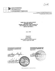
ELEHENTS OF AN UNDERGROUND PIPING SYSTEH.STORAGE TIINK VENTTRACTOR KSEHBLYTRNK FILL CV 4NDDROP TUBE ADAPTERSHUTOFF VALVEPIPEL INESUBRRGED TMNSFER PUHPSI;W6 JOINT AT ACHANGE OF DIRECTIONIII. , .~ . . .-. ‘. -1
What at-e some of the i;iiizrc? preval ent i ~stal 1 ati on @rr-6~t:-sregarding USTs?What are the API requirements concerning i nstal 1 ati on”?How can dewatering be accomplished?What bedding <strong>and</strong> hackf i 11 t-eyui t-ements are needed f car:!.”A) Fi berg 1 ass TanksP) Steel Tank::sHow does wet ho1 e ins.ta.1 1 ation differ from dry ho1 ei nstal 1 at. i on?Why <strong>and</strong> how is a tightness test performed?
IV, CORROSION CONTROI-SOURCES, SOLUTIONS AND CATHODIC PROTECTIONTank deterioration from corrosion is an important issue -'- it canbe a hazard to the environment. The source of corrosion may beinternal or external , The resulting leak can cause fire?e xp 10s i on r or environmental contamination. If internal corrosionis the cases there is the potential for product contamination.About nine percent of all <strong>tank</strong> leaks are the result of internalcorrosionz according to an American ~e~rC~leum Institute (API 1survey. It is important that whenever steel <strong>tank</strong>s are used!,internal corrosion is considered <strong>and</strong> preventative measuresapplied..*-..aAs the number of <strong>underground</strong> <strong>tank</strong>s increase, corrosion pi-fob lemsincrease. The cost of repairs or replacement of process <strong>and</strong>utility piping? hydraulic elevators7 electrical groundingnetworks7 electric power cables> Steel foundation piles3 <strong>storage</strong><strong>tank</strong>s> <strong>and</strong> other facilities can eventually affect ‘plant profits.Modern corrosion control <strong>practices</strong>, such as the use of engineeredcoating systems <strong>and</strong> the application of cathodic protection9 whencombined with proper design <strong>and</strong> material, can help eliminatecorrosion leaks <strong>and</strong> reduce plant operating costs.A. CHENICIIL IIIID BIOLOGICAL CORRO6ION CAUSESThe elements that contribute to corrosion on the inside of <strong>tank</strong>sare water3 oxygen <strong>and</strong> bacteria. The construct ion <strong>and</strong> use of the<strong>tank</strong> may be other sources of damage.1. WATERAn electrolyte is a liquid (such as waterjs paste or gas thataids the conduction of electricity. Corrosion from exposure toelectrolytes can occur on the outside surface of <strong>tank</strong>s. The soilinwhich <strong>tank</strong>s are buried is also an electrolyte. Soil <strong>and</strong>groundwater near an <strong>underground</strong> steel <strong>tank</strong> can act as anelectrolyte. By enhancing the flow of electrons in the electricalfield? the so i 1 <strong>and</strong> groundwater can create the conditions neededfor corrosion to occur.Water can enter the <strong>tank</strong> in different ways. For examplez it canenter from the product contained by the <strong>tank</strong>. It can also enterthe <strong>tank</strong> in the form of condensation. Atmospheric air can enterwhen the stored product is removed. Humidity is another source ofcondensation on the sides or crown of the <strong>tank</strong>. Condensation canOCCUt- on the <strong>tank</strong> walls.2. OXYGENFor internal corrosion to occurs oxygen must be present. It isc1”-\CORROSIONPROTECTION1
drawn into the <strong>tank</strong> through the vent when the product is removed.Water <strong>and</strong> oxygen in the <strong>tank</strong>: can form a generally uniformenvironment if they do not contain impurities. They may not causecorrosion of the metal. Uniformity is one reason why interalccirrosion is less prevalent than external corrosion. The <strong>tank</strong> ‘sexterior is sC\b ject to different soil types in the backfill. Thisvaried environment causes corrosion of the surface.3. BACTERIABacteria in <strong>storage</strong> <strong>tank</strong>s can feed on the <strong>tank</strong> bottom waters inaddition to hydrocarbons. The products of bacterial growth canset up localized corrosive conditions that cause severe pittingof metal surfaces.B. I’IECRARICAL SOURCES BF INTERNRL CBRRBBIBRInternal corrosiun has been found directly under the fill pipewhen a gauging stick is used tu measure the depth of the <strong>tank</strong>contents. Continued impact of the stick can the <strong>tank</strong> bottom canbreakdown any prcttective film that has developed on the bottom.The acticin exposes the bright metal continuously <strong>and</strong> leads toconcentrated carrosion. The continued pressure of incoming fuelon the bottom under the fill pipe also tends ta remove anyprotective film.Another factor can generate’ corrosion. Filling <strong>and</strong> emptying a<strong>tank</strong> affects the amount of oxygen <strong>and</strong> condensation to beexpected. When a thin film or ai 1 rust product bui Ids up on the<strong>tank</strong> bottumr corrosion can be reduced considerably. Also, if the<strong>tank</strong> bottom is smooth <strong>and</strong> the <strong>tank</strong> is installed in a slope-, waterwill collect at one end <strong>and</strong> may easily be removed.With flat <strong>tank</strong> battom surfaces9 it may be difficult to removewater from the level bottom surface. Eventually, dents <strong>and</strong>irregulaties in the bottom surface develop <strong>and</strong> provide pocketswhere water collects. .These imperfections <strong>and</strong> any impurities <strong>and</strong> slight metallurgicaldifferences such as welds, combined with oxygenated waters create lcarras ion .C. INTERRRL CORROSION SULUTIUNS1. PROTECTIVE FILMSA natural protective film can help reduce the possibility ofinternal corrosion. The film occasionally fco-ms as the <strong>tank</strong>bottom rusts* The film can be damaged if a foreign object getsinto the <strong>tank</strong> or in the area under the fill pipe. Pittingcorrosion occurs at these damaged points because the exposedmetal will be anodic <strong>and</strong> corrode relative to the entire <strong>tank</strong>bottom surf ace.2CORROSION PROTECTION IV: “-. - . ,
-s-B2. LINING AND COATINGOne of the best forms of protection against internal cclrrosion isa coating or 1 ining . On new <strong>tank</strong>s7 epoxy or urethane cctatings maybe used. These coatings are more difficult to use on existing<strong>tank</strong>s> because they require careful surface preparation beforeapplication.The most common method of lining an existing <strong>tank</strong> is with glassfiber. This is siometimes done when internal corrosion has beenfound but the <strong>tank</strong> is considered tu be worth saving..Glass fiber linings have to be properly applied <strong>and</strong> the surfaceproperly prepared. Tank corrosion occurs in areas where ,the1 ining breaks free of the <strong>tank</strong>.3. FILL PIPE SOLUTIONThere are two solutions to reduce corrasiun under the fill pipe.The installation of a striker plate below the fill pipe is onemethod. The plate prevents the gauging stick from striking the<strong>tank</strong> bottom <strong>and</strong> eliminates the mechanical abrasion from thegauging stick. Some <strong>tank</strong> manufacturers offer a shield under thefill pipe. The shield is attached tu the fill pipe <strong>and</strong> preventsthe gauging stick from striking the <strong>tank</strong> bottom. The shield alsc~diverts the incoming fuel Y reducing pressure on the <strong>tank</strong> bottom.4. CATHODIC PROTECTIONSacrificial zinc ribbons are placed in the <strong>tank</strong> bottom. 11 i ret tcurrent is made to flow from the zinc to the <strong>tank</strong> bottom:,overcoming the corrosion current. This is the same pratectic*nthat is often used on the exterior of piping, hydraulic elevatorcylinders? <strong>and</strong> <strong>tank</strong>s. This method is discussed in more detail inthe following section.5. FIBER-GLASS-REINFORCED PLASTICFRP <strong>tank</strong>s cummunly used for fuel <strong>and</strong> other hydrocarbon <strong>storage</strong>rrepresent an economical solution to corrosion problems.Although FRF’ <strong>tank</strong>s are immune to cccrrosianr they are not immune todamage. Fai lures in these <strong>tank</strong>s? reported in a 1981 API survey onglass fiber <strong>tank</strong>s? were the result of improper h<strong>and</strong>ling c1.f the<strong>tank</strong> I puncture by the gauging stick V <strong>and</strong> punt ture by construe t ionequipment. Proper h<strong>and</strong>1 ing during installation guards againstdamage.0. ~nlMlIC PRUKCTIONCathodic protection is widely used in industry to controlcorrc~sian of <strong>underground</strong> structures. In cathodic protection, adirect current is discharged into the electrolyte (ssoil) -fromspecial anodes <strong>and</strong> is picked up on the structure to be protected.II ,~,j This structure becomes the cathode of a new corrosion ccl 1..,,a,.3CORROSION PROTECTION IV
\!I!!!!!!s-Gt+H+!!!!!!!!!!!I!I!!!!III!IIIMI!\ .._Iv. . , ,..
_ ._. ., ._ ._ _. ,_ “. , __ . -..,.._. “,. .---. --.-Because corrosion occurs only at the anode, the special anode incathodic protection is sacrificed to protect the buried structure.The anodes are inexpensive ta replacer especially when comparedto the structure itself. If properly designed? anodes can have alife of 10 to 30 years or mare.1. GALVANIC SYSTEMIn this system, an anode9 usually made of magnesium or zinc> isplaced adjacent to the structure <strong>and</strong> connected to it with a wire.Because of the potential difference between the anode <strong>and</strong> thestructure $ a battery (corrasion cell) is created <strong>and</strong> currentf 1 COWS from the anode through the soi 1 to the structure. Theanodes can seldom produce more than 0.1 amp each. The galvanicsystem is usually installed when relatively small amounts ofcurrent are required. Typical applications are small-diameterbare piping, coated structures? domestic <strong>and</strong> industrial hot waterheaters3 heat exchanger water baxess sewage lift stations!, <strong>and</strong>structures in congested areas where large currents might affectcl ther structures. Galvanic anodes are usually distributed alonga r around the strut ture they pro tee t .2. IMPRESSED CURRENT SYSTEMImpressed currents are frequently used fur large-diameter piping?bare pipe such as cast-iron fire water mains, cross-country1 ines:, water <strong>storage</strong> <strong>tank</strong>s r hydraulic cyl inders (elevators9hoists) <strong>and</strong> <strong>tank</strong> farms. This system is more flexible than thegalvanic system. Anode beds usually last 20 to 30 years. Theimpressed current cathodic protection system with anodes9 usuallyconstructed of high-silicon cast iron or graphite? are cclnnectedtu a rectifier c&r other source elf direct current? <strong>and</strong> wired to thepro tee ted strut ture. Protective currents as high as severalhundred amperes can be impressed from such installatictns. Theimpressed current system is more flexible than the galvanicsystem. Greater effects un foreign structures are to be expectedwith the impressed current system? but these can be clearedthrough routine procedures.3. LIMITATIONSIn complex structures such as <strong>tank</strong> farms <strong>and</strong> pumping stations!,one structure may shield another from protective current. Adistributed anode systems? is often used to overcclme this problemsbut occasionally structures are sc~ close together that nothingcan be done.Consideration should be given tu the fact that cathodicprotect ion may affect structures ather than those beingprotected. Interference problems may develop in industrial plantswith a variety of <strong>underground</strong> structures unless the protect ionsystem is properly designed. Many structures may not beelectrically continuous with each other. Different b<strong>and</strong>s may he,CORROSIONPROTECTION4IV
IllPRESSED CURRENT CATHODIC PROTECTION TYPICAL CONFI6URATIONTEST BOX \llBOND WIREIPIISSTIVE HEADERCABLE-NEGATIVE BOND.-^*AIv, ,. _ ,, _ _ ., . .~“‘, ‘..
.-VWCE?S~d\-y to prevent stray current damage.Excessive cathodic protecticen can damage some metals? notablyaluminum <strong>and</strong> lead. These metals3 cal led amphctter ic 3 carrode underhighly alkaline conditions (pH greater than 8). Cathodicprotection causes an increase in pH around the protectedstrut ture. Flmphoteric metals can be adequately protected.However- f sufficient extra protective currents because of a largeincrease in pH! may cause those metals to corrode9 even thoughthey are protected. Protection systems must be specificallydesigned <strong>and</strong> monitored when dealing with items such as aluminumpipe <strong>and</strong> lead sheath cable.Cathodic protection is not an instant leak: stopper. Afterprotection is in place, there may be further leaks before anaticeable reduction in failures is noted. There are 1 ikely to bepits that have penetrated the pipe wall. A pressure surge mightcause the remaining wall to rupture. Hecause of corrosionproducts in the buttom of the pit) protective current may notreach into the depths of the pit. Carrosion wil 1 continue unti 1penetrationoccurs.Poor workmanship during cathodic prcltection can lead to problems.With impressed current z a nick in the wire insulation9 a poorlycoated splicer or a damaged anode connection will allow currentto discharge from the defect!, causing rapid failure. Wiring up arectifier backwards would be disastrclus. Excavations can breakwires. If the wires are not properly galvanized7 this can resultin additional problems. Galvanic anodes must be properly attachedto the structure to be effective. Careful inspection duringinstallation is essential.4. MA I NTENANCECathodic protection systems require proper maintenance.kect if iers need cccnstant power <strong>and</strong> require regular inspect ion. Itis recommended that plant personnel check the autputs monthly <strong>and</strong>make adjustments as needed. Galvanic anodes require 1 i tt leattention9 other than annual inspection.Any changes or additions to the <strong>tank</strong> may need changes in thecathodic protection. A corrosion engineer should be censul tedwhen the work is contemplated.An annual inspection of cathodic protect ion by a corrc~sialnengineer is recommended. The inspection includes a generalexamination of the system3 plus tests to check the adequacy ofprotection <strong>and</strong> uncover malfunctions.E. IXHODICRLLY PROTECTEP STEEL TANKSCarbon steel is the most cclmmcans mast versatile <strong>and</strong> least: costlymetal used in industry. It is two-thirds the weight of lead <strong>and</strong>three times heavier than aluminum. Carbon steel may be heated <strong>and</strong>CORROSIONPROTECTION5iIV
cooled to mak::e it stronger- <strong>and</strong> more flexible? <strong>and</strong> galvanized(coated with zinc) to improve its cclrrc#siCtn resistance. Themechanical properties of carbon steel are influenced by thecarbon content./I *_1,-".mibidThere are different types of carbon steel -- structural <strong>and</strong>pressure vessel steels. There are only small metallurgicaldifferences between these types of steel. The importantdifferences are in the quality of the steel.There are a number of st<strong>and</strong>ards <strong>and</strong> specifications fctr carbonsteel in various fclrms, such as in the form of bars? pipe <strong>and</strong>plate. The American Society for Testing <strong>and</strong> Materials (ASTM)publishes specifications on many materials of cc~nstructianincluding carbon steels. The American Iron <strong>and</strong> Steel Institutealso issues specifications on a variety of carbon <strong>and</strong> allaysteels.1. COATED STEEL TANKSInterior coatings are often called <strong>tank</strong> linings. Coatings <strong>and</strong>linings are generally applied at the factory for shop-assembled<strong>tank</strong>s. Follow <strong>tank</strong> manufacturers’recommendations when a coatingis required since improper selection can lead to an early failure<strong>and</strong> product contamination. Avoid damage when installing the<strong>tank</strong>.2. GALVANIC PROTECTIONCathodic protection reduces cir eliminates corrc8sion of a metallicstructure in contact with corrosive soi 1. It is recommended toapply an electric current to the structure which is greaterin strength <strong>and</strong> opposite in direction tu the current causingcorrosic?n.Galvanic cathodic protection uses sacrificial anodes, cc~mpused ofmaterials.such as magnesium or zinc:, in electrical contact withthe metal structure ta be protected. The anodes are attached to -the surface ccf the protected material (<strong>tank</strong> or pipe) in the soilar other electrolytic sc~lution. The required current is generatedby corrosian of the sacrificial mode.The amount of electric current required to protect the <strong>tank</strong>:: isdetermined. Soil resistivity is determined in carder to determine .type <strong>and</strong> size of anode(s) required to protect the <strong>tank</strong>. The lifeexpectancy of the <strong>storage</strong> system is also important in determiningthe number <strong>and</strong> types ccf anodes required.Magnesium anodes are the must cc~mmon type of sacrificial anode.Zinc anodes may alsca be used in soils with resistivities lessthan 1 (XK) ohm/cm . Because of its higher driving voltage:.magnesium can be used effectively in sails with resistivities upto 3300 ohm/cm. On well-coated structures3 it can be used up to10 :, WK) ohm/cm or more .CCIRROSION PROTECTION IV
.From both an ecanomic <strong>and</strong> engineering st<strong>and</strong>point3 it is best ttTatgalvanically protected <strong>tank</strong>s be coated. Bare <strong>tank</strong>s need moreelectric current <strong>and</strong> a larger number of sacrificial anodes thancclated <strong>tank</strong>s.It is important to test cathodic protection periodically. Thiswill ensure the system is operating properly <strong>and</strong> will providelong-term protection. The current from anodes may fai 1 because ofanode deterioration or broken lead wires. Changes in undergraundcclnd i t ions ar coating deterioration can also change protectivecurrent requirements. Measure <strong>tank</strong>-to-soil potentials <strong>and</strong> anodeoutput annually to ensure proper operation of the system.To ensure electrical continuity of the system7 provide bond wiresbetween <strong>tank</strong>s when several <strong>tank</strong>:s are installed <strong>and</strong> acrctse;flexible pipe joints. Do not rely on screwed piping to provideelectrical continuity.Examples of pre-engineered? galvanically protected steel <strong>tank</strong>sinclude the Sti-P3 <strong>tank</strong> <strong>and</strong> the ST-10 <strong>tank</strong>. These are st<strong>and</strong>ardsteel <strong>tank</strong>s with three levels of corrosion protection: c:athudicprotection; a protective coating <strong>and</strong> electrical isolation.High-potential magnesium anodes are permanently attached ta theheads of each <strong>tank</strong> to provide a flow of protective current. InSti-P3 <strong>tank</strong>s? anodes are packaged in a special moisture-holdingmaterial which improves conductivity <strong>and</strong> current flow fromanodes. Coal-tar epoxy or urethane coating is the secondprotective component in these systems. The third component iselectrical isc~lation. This protects the <strong>tank</strong>s against straycurrents that could otherwise reach them through pipingconnect ions. If internal carrosion is a concern? striker plate?internal welding or internal zinc strips which serve assacrificial anodes are an caption. If the stored product is notcompatible with steel 9 an internal lining of compatible materialshould be appl ied.3. IMPRESSED CURRENTS FOR STEEL TANKSThe impressed current cathodic protection method uses a directcurrent provided by an external source. The current is passedthrough the system by use bf non-sacrificial anodes such ascarbon r nun-currodible alloys, or platinum. These anodes areburied in the grc~und or suspended in the electrolyte <strong>and</strong>connected to the positive terminal of the external power supply.Tanks <strong>and</strong> other structures to be protected are connected to thenegative side of that power supply.Impressed current cathodic protection systems are frequently used .at service stat ions. Cathodic protection systems are especiallyapplicable far <strong>storage</strong> situations in highly corrosive scli 1s.Because of the large power supply (electric current 1 provided bythese systems!, they are used ta protect bare as well as c:oat.ed<strong>tank</strong>s.7CORROSION PROTECTION IV
A big advantage of impressed current is that short circuits canbe avercome more easily than with sacrificial anode systems. Thishelps installation3 especially when electrical continuity must beinsured between two or more <strong>tank</strong>s. Disadvantages of these systemsare high power consumption <strong>and</strong> greater chance of electricalinterference on foreign structures.Periodic testing is necessary. Current may fail because ofrectifier malfunction or interruption of power. The system shouldbe tested according to manufacturer’s instructions <strong>and</strong> ad justedas needed. Once per year? the <strong>tank</strong>-to-soil potential should bemeasured to check the adequacy of protection <strong>and</strong> determine ifrectifier adjustments are needed.wT7n8CORROSION PROTECTION IV
iiim-h1%‘3?:!IB.:::g-3.iii:E:3ID L’Incl. wiiiCl. 2,-k.i:irl .:..n wtn i-Ja. ._ ‘j !aI-J.3
u, TC1NK T-ES-T-INGMETHODS FOR LOCATING TANK LEAKSIf an <strong>underground</strong> leak is undetected, one or more of the followingproblems may develop:o the leaking substance or its vapors may find their way intebasements of nearby’ buildings. If the substance is flammableor reactive, it may create a fire or explosion hazardo the leaking substance can seep into sewer r;ystems, thu.5spreading the contamination $0 other areas, often far awayfrom the leak sourceo the leak:ing substance or its .vapors can seep into thegroundwater f contaminating drinking water suppliesTank leaks should be detected early before they have a cha.nce tospread <strong>and</strong> cause extensive damage. Regular testing <strong>and</strong> in:spectionsof <strong>tank</strong> <strong>and</strong> pipino are ways to ensure leaks are prevented, ordetected early if they should occur.b, TANK TESTING HETHODSTests are conducted to determine the tightness of <strong>underground</strong>starage <strong>tank</strong>s <strong>and</strong> piping for the following purposes <strong>and</strong>conditions:o routine inspections <strong>and</strong> maintenanceo suspicion of leak due to stock inventory losseso when leak monitoring indicates ground contamination, an:d thecause is not'determined from surf ace observationo when there is an accumulation of water in the <strong>tank</strong>0 following constructionThe tests typically include filling the <strong>tank</strong>: with a fluid? usuallywater I or air until reaching a certain pressure <strong>and</strong> observing if a1 ass of f 1 ui d or pressure occurs due to an ex i sting 1 eak.A variety of methods may be used to detect leaks <strong>and</strong> determinetightness of a tan!:: <strong>and</strong> its associated piping. Each method hasits applications <strong>and</strong> limitations.1. PNEUMATIC TESTINGAir pressure (pneumatic) tests can be performed when: (1)non-flammable liquids are stored; (2) water or other suitableliquid is unavailable; <strong>and</strong> 13) water in the <strong>tank</strong> may contaminatethe product stored. St is best to avoid air testing if the <strong>tank</strong>is badly corrcded. Low-pressure <strong>storage</strong> <strong>tank</strong>s 23~; well a5atmospheric <strong>tank</strong>s can be tested with this method. Low-pressure<strong>tank</strong>s are tested at slightly higher pressures depending on theirdesi gn.TANKTESTING1v
-“..,The primary disadvantage of pneumatic tests i c; that they arenot sensitive enctuuh to detelzt slow leaks. Their preci si c!n islimited by the readings of a stick gauge <strong>and</strong> the amount of productin the <strong>tank</strong>.2. HYDROSTATIC (STANDPIPE) TESTINGHydrostatic tests involve pressurization of a <strong>storage</strong> systemby connecting a st<strong>and</strong>pipe to a completely filled <strong>tank</strong>::. Anadditional head is placed on the <strong>tank</strong> by filling the st<strong>and</strong>pipe,generally to an elevation such that a pressure of 5 psi is exertedat the bottom of the <strong>tank</strong>. A leak is detected by obset-viny? a dropof the liquid level in the st<strong>and</strong>pipe. The amount ef the l.eak canbe determined by measuring this level drop.This test ic, useful where it i s desired to test an<strong>underground</strong> <strong>storage</strong> <strong>tank</strong> <strong>and</strong> its connected piping for grossleaks.-7.-, = HEATH FETRO-TI TE TANK GND LINE TEST I NG SYSTEMSI Kent -Moore Test !This method is a hydrostatic test that cempensatez fortemperature, pressure <strong>and</strong> viscosity variation. This enabl.es leaksas small as 0.05 gal/hr. to be easily detected. The test requiresexerting a pressure head on the <strong>tank</strong> by means of a st<strong>and</strong>pipefilled with the same liquid stored in the <strong>tank</strong>. A pump circul at-esthe 1 iquid to produce a uniform temperature throughout the <strong>tank</strong>.Temperature changes are precisely measured to account forexpansion <strong>and</strong> contraction of the liquid. Volumetric measurementsare correspondingly adjusted for changes in temperatures. Bycomparing the product added or drained with the volumetric changesanticipated because of temperature changes;, it is possible todetect a leak as small as 0.05 gal /hr.For <strong>storage</strong> systems with submerged pumping, the Kent-Mooretest must be run separately on the <strong>tank</strong>:: <strong>and</strong> on the piping for goodresults.The Kent-Moore test requires several hours for completionwith accurate results. Because af the extensive shut-down timerequirements <strong>and</strong> the level of skill involved, the Kent-Moore testis relatively expensive to perform.4. J-TUBE MANOMETER TESTThe J-Tube is a manometer-type instrument capable ofmeasuring very small drops in product level caused by tan,kleakage. The J-tube leak detector wi 11 detect leaks that causevariations in <strong>tank</strong> product level as small as Ct.02 inches.Advantages cf the J-tube, field-tested by Texaco, are:ej.w: 0 relative ease of transport, assembly <strong>and</strong> operationp-12TANK TESTING v
it does not intensify e.xistinq leaks or create new leaks?since no hydraul ic or air pressure is usedaccuracy is a function of the time span of the test. l-he te5tcan measi!re major leaks in a short time period <strong>and</strong> minorleaks in a longer time periodit does not require a contractor crew to operate <strong>and</strong> no <strong>tank</strong>truck de1 i very i s requiredseveral <strong>tank</strong>s can be tested simultaneously<strong>underground</strong> <strong>tank</strong> T piping <strong>and</strong> dispenser openings need not besealedOne disadvantage of the J-tube leak detector is that it willnot detect leaks above the product 1 eve1 in the <strong>storage</strong> <strong>tank</strong>,5. SUMMARK LEAK DETECTION TESTThe Sunmark Industries Leak Lokator is a system capable ofdetecting <strong>and</strong> measuring volume changes in <strong>underground</strong> <strong>storage</strong>systems. It was principally developed for use on gasoline <strong>storage</strong><strong>tank</strong>s but could be used for other liquid <strong>storage</strong> systems as we1 1 mThe equipment is capable of differentiating between piping leaks<strong>and</strong> <strong>tank</strong> leal::s.Ea5ic equipment consists of a sensor, an analytical balance, <strong>and</strong>a chart recorder. The sensor is an open top, hollow tube filledwith the liquid contained in the <strong>tank</strong>. It is suspended fromthe analytical balance <strong>and</strong> partially submerged in the <strong>tank</strong>::1 i qui d. The liquid level in the <strong>tank</strong> changes.. This change ofmass displacement measured by the analytical balance is anindication of volume changes within the <strong>tank</strong>. The chart recorderprovides a graphical representation of volume change versus time.6. LASER-EEAM LEAK DETEGTI @NSRI International, a California-based research <strong>and</strong> .development company, is developing under contract to AF’I a.nexperimental device for detecting leaks. The device operates byaiming a laser beam down into the <strong>underground</strong> <strong>tank</strong>. Upon strikingthe liquid surface, the beam is reflected back to a detector whichcomputes the liquid level in the <strong>tank</strong>. A change in liquid: leveldL!ring the test indicates a leak in the <strong>tank</strong>. Tests perf olrmed todate.indicate it is capable of detecting changes in liquid; levelin the order of microinches. The threshold of detection has notyet been establ i shed.7. ARGO LEAK TESTThe Arco HTC Storage Tank Leak Tester uses a float <strong>and</strong>light-sensing system to detect volume changes in <strong>underground</strong><strong>storage</strong> <strong>tank</strong>s <strong>and</strong> their distribution lines. The system can be usedfor any 1 iqui d whose density can be measured. It is unaffected bytemperature changes that occur in the <strong>tank</strong> during the test.Measurements can only be taken when the <strong>tank</strong> is inactive <strong>and</strong>contains between 70 <strong>and</strong> 82% of its volume (M-75% of liquidTANK TESTING
..^IN-TANK TESTING SYSTEH/HANHOLE FOR PROBE ACCESS- FILLER RISER PIPELIQUID LEVELPROBEDETAILMNHOLEl-l
. ..^ -depth).This leak:: tester consists of a float that is positioned ata particular depth in the tan!:: <strong>and</strong> a detector that is usua.llyattached to a support rod.The primary drawback of this test procedure is that itmust be conducted with the <strong>tank</strong>:: 66-76X f ull . Thus Y it is notpossible to detect leaks in the upper 25% of the <strong>tank</strong>.8, PIPELINE TWIN6 PROCEDURESNFPA 30 St<strong>and</strong>ards require that all pipelines for <strong>underground</strong><strong>storage</strong> systems be tested prior to being covered, enclosedor placed in use. These st<strong>and</strong>ards require either hydrostatictesting, pneumatic testing, or an approved equivalent.1. SUCTION PIPING TESTIf the pump used in moving the liquid is aboveground, thesupply pipe operates under a suction head <strong>and</strong> certain pumpingcharacteristics indicate either a leaking check:: valve or a leakingpipe. If there is a leak, air will enter the pipe as liquid drainsback into the <strong>tank</strong> through the check valve or through a pipe leakinto the ground. The presence of air will be indicated by theaction of the pump in the first few seconds of operation after anidle period. If the pump is equipped with a meter <strong>and</strong>cost/quantity display device such as is found in a gasolineservice station, pumping of air is indicated by the display wheelsskipping or jumping.Other signs of air in the suction line are:o the pump is running but not pumping liquido the pump seems to overspeed when first turned on <strong>and</strong> thenslow down as it begins to pump liquido a rattling sound in the pump <strong>and</strong> erratic liquid flowindicates air <strong>and</strong> liquid are mixedIf the pumps do not exhibit the symptoms of a leak as describedabove but there is still reason to suspect a pipe lea):, or9 if acomplete system check has been performed <strong>and</strong> it is now necessaryto isolate <strong>and</strong> check the piping system, individual pipe runs maybe isolated <strong>and</strong> pressure tested.2. DISCHARGE LINE TESTINGPumps are often located in the <strong>tank</strong>, or rarely, just abovethe <strong>tank</strong> but remote from the dispensing devices. The pipie to thedispensing equipment operates under pressure. A leak in this linecan cause rapid loss of pressure after the pump is. turned off.-*To hold pressure at the dispenser end, shut off valve at base ofthe dispens.ers or close any upstream hose. The pump end can be*.a.\TANKTESTING
sealed c?f f by setting the check <strong>and</strong> r-e1 ief valves in the head ofthe pump * The ct-leck valve i 5 readi 1 'y acce55.i bl is i ri the manhol iIover the pump. Most are equipped with a screw ur bolt supplied furthe specific purpose crf positively seating these valves far- linecheck::i ng. A pressure guage should be installed in the line. Apressure difference of 5 psi per minute indicates a probable1 eak ./-a 3sc. PHYSICAL INSPECTIIJNPhysical inspections detect existing leaks in the <strong>tank</strong> or itsassociated piping, <strong>and</strong> prevent sudden failure of the <strong>tank</strong> hyperforming certain tests that determine its tightness <strong>and</strong>structural strength. Fhysical inspections include the external aswell as internal inspections that can be performed on undergrc?und<strong>storage</strong> systems.1. INSFECTIONS PRIOR TC! EACKFILLINGThese physical inspections range from srjap tests, whichinvolve soaping down a pressuri zed <strong>tank</strong> <strong>and</strong> check:ing fc!r lea!::s(huhhlesf, to more detailed internal <strong>and</strong> el:ternal non-destructivetests such as ultrasonic teE.ts? spark tests, <strong>and</strong> deflecticmmeasurement5.Deflertien measurements can be performed internally onfiberglass <strong>tank</strong>s or any other flexible <strong>underground</strong> <strong>tank</strong>:: thatdepends an the strength of the underlying sail for structuralsuppurt . Such measurements could be made ta evaluate thestructural strength <strong>and</strong> integrity of <strong>storage</strong> system campcnents,Deflection can easily be measured prior tee piping installation butmight require excavation afterward.Other testing <strong>techniques</strong> such as ultrasqnic tests, acousticemissions tests? spark tests <strong>and</strong> the use of radiation-typeinstruments may be used to internal1 y ur externally inspect <strong>tank</strong>spriGr tG backfilling.w_*i2. INTERNAL INSPECTION OF INSTALLED TANKSUnless <strong>underground</strong> <strong>tank</strong>s are contained in an accessiblevault ? external vi sual inspect i ons are not pussi hl e wi thoutunearthing the <strong>tank</strong>. Internal inspections may he perfarmed if the<strong>tank</strong> is equipped with a manhole. Ultrasonic <strong>and</strong> radiatitx-typetests may be used in these cases. Spark tests may be used in <strong>tank</strong>sthat da not cantain flammable or combustible materials.^-,Caution should be taken when entering a <strong>tank</strong> because internal<strong>tank</strong> inspection is hazardcxts. The <strong>tank</strong> should be emptied <strong>and</strong>gas freed. It should also be washed <strong>and</strong> cleaned prior to enteringthe <strong>tank</strong>. A breathing apparatus <strong>and</strong> fire-resistant Clothingshould he worn upon entering a <strong>tank</strong> that ctlntained flammablematerial.TANK TESTING v
Failure tG find a leak:: by the follawing tes.ts does nc?t indicatethat the <strong>tank</strong> is leak free. But if it does reveal a leak, amGre canclctsive test is unnecessary. _Many <strong>tank</strong>s develop leaks in a narrow h<strong>and</strong> along the bettclm..This is because small amclunts Gf water condense nut af mostliquids, <strong>and</strong> settle at the bGttGm cltf the <strong>tank</strong>: to cause internalcorrosion. The prnhlem is of ten aggravated by gauge sti CC::‘%hitting the <strong>tank</strong>: hottam <strong>and</strong> causing localized corrosiilsn <strong>and</strong> leaksunder the fill pipe. Washing may also occur cinder the f i 11tube. IncGming liquid may be able to flush a thin film ofcGrrc3siGn off the steel 7 further exposing it ta more curro~aion.To test for these leak::s, mak::e a prclbe by driving a f inishi nq nai 1intG the end G+ a gauge stick leaving about 3/4 inch prc&ruding.The gauge stick is then used ta check fGr a hGle in the <strong>tank</strong>bottom under the fill pipe by probing or “feeling” the bo,ktamwith the nail head. The test requires a 1 ittle technique that isquickly learned <strong>and</strong> has been quite successf c!l .Leaks along the hattom can he detected by a simple test ofmeasuring a drap in liquid level. The test requires adding waterta the <strong>tank</strong> <strong>and</strong> gauging the level with finding paste. It is notconclusive, but the test will reveal the existence af large leaksin the <strong>tank</strong> bottom. This methad can he used with petraleum <strong>and</strong>other lighter-than-water 1 iquids. The test canncst be used if thegrcrcindwater table is higher than the liquid level.4. CHECKING FOR WGTER IN TANKSThe <strong>tank</strong>’s water content can he determine when gauging the <strong>tank</strong>bath during de1 i ver-i es <strong>and</strong> ir:ventary checks by using a waterfinderpaste smeared on the bottom partian of the gauge stick.fin unaccountable increase in the water level may indicate a <strong>tank</strong>::1 eat:: 7 especially if the increase cxcurs after a heavy rain.Before concluding the presence of water is due to a faulty <strong>tank</strong>,the fill cap, its seal9 <strong>and</strong> other connections should be checkedto insure that they are praperly in place.Water presence may also he detected using a water detector. Thedevice sounds an alarm when it ccrmes into contact with the waterlayer inside the <strong>tank</strong>. The depth af the water layer can beaccurately measured by raising the probe until the alarm stGps.If a significant amount af water is detected (above the pumpsuction pipe), the <strong>tank</strong> should be tested far leaks= Pump cut <strong>and</strong>treat the contaminated water as required by lacal law or pumpinto a <strong>tank</strong> truck for prGper off-site disposal.5. INSF’ECTION OF CXTHODIC Fl7lLTECTI!X’J SYSTEMS CHEC.KING FOR WATERIN TANKSWhen the <strong>tank</strong> (Irr associated piping is equipped with cathcldic6TANK TEST I NG V
protecti on s inspect i on <strong>and</strong> maintenance of the cathocdi c pt-Gtecti orisystem is. es.sential if it is to $Lcnctiorl prGper1.y <strong>and</strong> providelong-term protection. In the cacrp -- of impressed current systems.current may f ai 1 berause of anode deteri orati Gn? broken leadwi re5* rectifier malfunction Gr interruption of power. Impressedcurrent rectifiers should be checked monthly <strong>and</strong> adjusted asneeded. Monitor the output of rectifiers with a voltage Grcurrent i ndi cator I At least once a year, tak::e <strong>tank</strong>-to-soi 1measurements to check the adequacy of protecti on <strong>and</strong> determineif any rectifier adjustments are needed.Gal vani c anode systems must he periodically tested. Measurementsof <strong>tank</strong>-ta-sail potential <strong>and</strong> anode outputs should be made at1 east annual 1 ys although there are no electrical components tomaintain. So-call ed “maintenance free” gal vani c systems aresusceptible to the same failures as other galvanic systems, Onboth systems a potential 0.85 volts <strong>tank</strong>-to-soi 1 is cons.idered tobe adequate protectian.TANKTESTING7V
REFERENCE5/a,
What are some hazards 12-i: leaking US'Y's.List <strong>and</strong> describe 7 <strong>tank</strong> testing methods=Li 5.t at-jtj cjescy-i he 2 pipeline testing methods.
VI w LEAK f)ETECTIC3NTANK MONITORING AND SPILL PREVENTIONSystem monitoring includes early warning lea!:: detection sgstemsthat provide continuous surveillance for leaks <strong>and</strong> spills.Area-wide survei 1 lance methods may be used to investigate orpinpoint the source of a spill or leak.System testing refers to special equipment <strong>and</strong> methods not partof normal operations. Testing determines whether a <strong>tank</strong> or pipesystem is leaking at a particular time,A. EARLYARNING LEAK DETECTION SYSTEMEarly warning leak detection systems provide conti nuoussurvei 11 ante for the presence of a leak: or spi 11 jl Most commorr 1. v Iused types are:o Inventory monitoring Ialso called inventory control)o Interstitial monitors in double-walled <strong>tank</strong>s0 Systems that monitor the <strong>storage</strong> <strong>tank</strong> excavation. Thesetypes of systems include observation well? U-tubes, <strong>and</strong>wire grids. The types of leak sensors include thermalconductivity sensors, electric resistance sensors, <strong>and</strong>gas detectorsi.INVENTOl?~CONTROLRegular inspection of visible parts of the product h<strong>and</strong>lingsystem <strong>and</strong> prompt recognition of leak conditions are importqit.Evidence of leakage from buried tant::s <strong>and</strong> pipelines can begathered from inventory control records <strong>and</strong> from abnormaloperation of pumping equipment. Fol lowing are the obvioussymptoms of leaks:- Product loss in a <strong>tank</strong> when a product is not dispensedusually indicates a leaking <strong>tank</strong>. It might also indicatefaulty accounting or metering of the product3 theft, orextreme temperature change.- Increase in water in an <strong>underground</strong> <strong>tank</strong> if groundsurrounding it is saturated. Water may leak into the<strong>tank</strong> instead of product leaking out. A leaking gaugeor fill cap should be examined <strong>and</strong> made watertightbefore cuncluding the <strong>tank</strong> is at fault.- Increasing differences between the amount of productreceived <strong>and</strong> dispensed may indicate a meter calibrationproblem, theft, or a leak: in <strong>tank</strong> or piping.- Where fill boxes are located remotely from the <strong>tank</strong>s,large differences appearing consistently between amountsinvoiced <strong>and</strong> <strong>tank</strong> gauges after deliveries may indicate aleak in the remote fill line. Test the line.“*-em1LEGK DETECTION VI
- Hesitation in the delivery from a st<strong>and</strong>ard dispensingpump rna,y indicate a, leak in %he suction piping. It ma.‘+al so be caused by a leaking foot valve or in warmweather ., vapor 1 oc k .- In a remote pumping system9 meter spin without productdelivery may indicate a leaking pipe.- Gasoline odcr in spaces below ground adjacent to <strong>tank</strong> maybe evidence of <strong>underground</strong> 1 eaks whether in <strong>tank</strong> orpiping. The odors may also be evidence of product spi 1’1sduring product delivery <strong>and</strong> <strong>tank</strong> filling.It is important to notify peopl e responsible for maintaining theequipment if '~OLI observe any of these symptoms. Attempting tocorrect the condition is not recommended. The operation m’ay behazardous <strong>and</strong> require special equipment. In some locations, cx3lyspecial licensed mechanics can work on <strong>storage</strong> equipment.Factors limiting the accuracy of inventory control as a leak:detection method include:1.1 Product thermal expansi on. Fl uctuati ons i n temperature canlead to expansion p contracti on ‘I evaporation <strong>and</strong>.s'orcondensation of the stored product. This affects inventorymonitoring results.2) Errors associated with faulty reading of dip stickmeasurements.3) Errors associated with resolution in meter readings. Al 1meters have aA associated level of error, typically on theorder of 0.5X of the level of resolution of the meter.Inventory control Y carefully carried out, is the first defenseagainst 1 eaks.i. ? INTERSTITIAL MONITORING IN DOUBLE-WALLED TANKSfin early warning monitoring technique characteristic ofdouble-walled <strong>tank</strong>s involves monitoring space between inner <strong>and</strong>outer walls of the <strong>tank</strong>, using either fluid sensors or pressuresen s.or s . Use pressure sensors to monitor <strong>tank</strong>s that either have avacuum drawn in the space between wal Is, or have that spacepressur i z ed. Failure of either the inner or outer wall is.detected by 1 oss of vacuum or pressure. Fluid sensors3, oln theother h<strong>and</strong> f would be located between the <strong>tank</strong> walls to detect thepresence of a liquid due to failure of the inner wall (detectingstored product) or the outer wall (detecting water).3. TANK EXCAVATION MONITORING SENSORSTank excavation monitoring systems are aimed at detecting a spillor lea!:: before the contamination spreads beyond the <strong>tank</strong>excavation or its immediclte surroundings. The leak or spi 11sensing mechanisms that may be used in <strong>tank</strong> excavation monitoringsystems include thermal conductivity sensors, electricalresistivity sensor5! gas detectors <strong>and</strong> sample analysis.LEAK DETECT I ON VI
FIBERGLASS-REINFORCED PLASTICDOUBLE-MLLED TANK WITHBUILT-IN LEAK DETECTIONDIPiTICKFILLING TUBE&--- VENTILATION/==ILEVELFLOAT VALVE -/+$I?73--.-w--buLEAKAGEWARNINGSYSTENlINNER TANKTANK LEVEL INDICATORVI
- Thermal conducti vi ty sensors. Thermal conducti vi t--y sel~~~.or~.detect changes in the thermal conductivity of their surlroitrjdingenvironment to determine if a leak or spill has occurred, J-h ac.m ___type5 of sensors can be used in wet or dry applications (i.e.areas of either low or high groundwater), <strong>and</strong> are particularlyapplicable for the detektion of hydrocarbons such as gasoline,gasohol, fuel oils3 alcohols, <strong>and</strong> trichloroethylene.- Electrical resistivity sensors. Systems employing this leakdetection technique rely on the change in resistance in a wiredue to exposure to the stored product to indicate the presenceof a leak or spill. The key to systems of this type is the useof wires or wire coatings thaf are highly susceptible todegradation when exposed to stored product. Bare steel wiresmay be used in acid <strong>storage</strong> areas or bare aluminum wires may beused in areas storinq caustics. If the stored liquid is notcorrosive to metals, the wires must be coated with a degradablematerial, such a5 rubber coatings in areas storing aromaticsolvents. The wires in turn are connected to an electricalsensing device that passes a current through them to evaluatetheir electrical properties. Any degradation of the wire or iti;coating results in a signif icant chanqe in the circuitresistivity, indicating the existence ctf a product lea!:: orspill.- Gas detectors. Gas detectors are available to detect a larqenumber of combustible <strong>and</strong> non-combustible qases <strong>and</strong> vapors.These types of devices are generally appl icable in areas ofpermeable soil 'or trackfill, where gases <strong>and</strong> vapors are 1 i kelyto migrate easily. Gas detectors are particularly applicablein instances where the stored praduct is highly volatile <strong>and</strong> the<strong>storage</strong> area (excavation) is relatively dry (free ofgroundwater) .- Sample collection. This involves collecting samples from awell in the excavation area. Sample collection is an accuratebut expensive method of leak:: detection that is applicable inareas of high qroundwater where direct qroundwater contaminationis of concern. Sample analysis is perf armed by such <strong>techniques</strong>as mass spectrometry <strong>and</strong> gas chromatography. Sample collectionis an intermittent as opposed to a continuous monitorinqtechnique. Sample cannot be collected 24 hours a day, 365 daysa year.4. TANK EXCAWTION MONITORING SYSTEMSThere are several types of leak monitoring systems which m.ay beemployed using leak sensors or detection <strong>techniques</strong> describedabove to detect leaks in or around <strong>underground</strong> <strong>tank</strong>: <strong>storage</strong>areas. These system types include:- Wire gridsThis leak detection system uses electrical resistivity sensorsin a wire grid located either within or just outside thecontainment region (just inside or outside the containment areasynthetic liner). The wire grid is connected to a mini-LEAKDETECTION
computer that continuously monitors the electrilzal propertiesof each wire in the arid. If a leak: occurs7 the mini-computer c<strong>and</strong>etermine which wires in the grid have had their electricalproperties altered, thereby identifying the location <strong>and</strong> extent ofthe leak. One drawback:: is that this system is susceptible to beingdisabled by a spill,- Observation wellsObservation we1 1 s are most common1 y us.ed in areas of hiqhgroundwater I where the <strong>underground</strong> <strong>tank</strong> is 1 i kely to beanchored in qroundwater during normal operation. The we1 1s usemany types of leak sensors to provide continuous leaksurveillance.- U-tubesA U-tube typically consists af a 4-inch diameter ischedule 40:)PVC pipe. It appears to offer an economical method formonitoring <strong>and</strong> recovery of leaks <strong>and</strong> spills at underqroundinstallations. When installed without an underlying imperviousliner it functions on the assumption that a leak will trickledownward along the exterior surface of the tan):: <strong>and</strong> drip off thevery bottom directly into the U-tube. These systems ar’z mosteffective in areas of low qroundwater, where it is unlikelythat the <strong>tank</strong>:: will be exposed to qraundtiater during nor!maloperation. U-tube install ations can be used in conjunctionwith observation wells in areas where the qroundwater tablelevel is known to fluctuate to a level above the bottom of thestoraqe excavation,B. AREA-YIDE SWEllLANCE NEllUtDSThese methods investigate or pinpoint the source of a known leakor spill.i alI. DYES AND TRACERSUs;e dyes <strong>and</strong> tracers to track down a source of qroundwatercontami nation. The technique injects a strong dye or tracingmaterial into a <strong>storage</strong> <strong>tank</strong>: suspected of being the source ofcontamination <strong>and</strong> monitoring the point where contamination wasfirst discovered for the appearance of the dye or tracer.Available dyes <strong>and</strong> tracers include organic <strong>and</strong> fluorescent dyes,metallic tracers, ultraviolet tracers, <strong>and</strong> radioactive tracers.:..-a2. MONITORINS WELLS“.“,.
tlONITORIN6 WELLGRADESENSORS#TER TABLECOVENTIONAL UNDERGROUND TANK-vPERMETER OF WASTE DUNPWATERINDUSTRIAL WClSTE DUHPNONITORING WELLSECONDARY \UNDERGROUND TlNK WITHIN A CONTAINRENTVI
- The monitoring well samples a very small part i;a point) of thesoi 1 or qroundwater thereby 1 i miting i tE. representatives to thequality (3-f the soi 1 or groundwater in the immediate vicinity ofthe well- The extraction of well samples may be difficult because of thetightness of the geological formation or the depth of thegroundwater.- Determination of the groundwater flow rate <strong>and</strong> direction areprerequisites to determining the placement of qroundwat,ermonitoring wells.- Groundwater flow rates are extremely slow (typically varyingfrom one foot per day to much lessi), resulting in acorresponding slow change in water quality at a particular well.This phenomenon could require data collection over lonq periods.of time (months or years).Types of Site Data Needed to Design an Appropriate GroundwaterMoni torinq F'r-oqramGeuloqic:o surface qeoloqy (topography <strong>and</strong> tvpe/depth of overburde!n>o litholoqy af aquifer0 type of geology formation (local stratigraphy?Hydroqeologic:o depth to water tableo water-like contoursa thickness of aquifer(s)o relative hydraulic heads, if more than one aquifero annual precipitationo aquifer permeability <strong>and</strong> porosityGeochemical:o background water qualityo chemistry of geologic formationo presence of other sources of chemical or biologicalcontaminationC. RECOVERY WELLSRecovery wells may be used to recover oil or any other hazardousliquid that has been spilled <strong>and</strong> is floating on the qroundwatertable. Such wells are located to take advantage of naturalgradients or induced gradients in the groundwater table indrawing out the contaminated water.Consider these factors when establishing a recovery well program:o the required pumping rate to recover product from theqroundwaterLEAK DETECT I ONVI
U-TUBE INSTALLATIONOBSERVATION WELLOVERFILL PREVENTION DEVICE WITHEXTRACThBLE TEE TO GRADE\
D.n the establishment of a we1 1 network:: that ensurefz. adequatecoverage cf the spi 11o the prevention af soil contamination during recoveryaperationso existing environmental <strong>and</strong> public health st<strong>and</strong>ards which willbe used to determine when spill recovery aperations have beencompleted satisfactorilya the required depth of the recovery well0 gecjlcrgic formation(3 required well diameterOVERFILL PREVENTION SYSTEM FOR UNDERGROUND STORAGE TANKSk good <strong>underground</strong> <strong>tank</strong>:: overfill prevention system wouldinclude the fallowing basic elements: 1) a level sensing devicethat monitors <strong>and</strong> indicates the liquid level in the <strong>tank</strong>::; 2) analarm to alert the operatar af an impending overfill condition;<strong>and</strong> 3 1 an autc?matic shut-off device that stops the flow af theproduct when the <strong>tank</strong> is full.Werfill protection is accomplished by measuring <strong>and</strong>contralling the level of liquid in a <strong>tank</strong>. A partial system rrra’yinclude only a gauge which indicates liquid height in the <strong>tank</strong>. Asuphisticated system could include autamatic flaw control system<strong>and</strong> a backing audible high level alarm to warn the operator crfemergency conditions.Cs gcrrocl averfill system prevention system includes:a Level sensing deviceu Level indicating deviceo High level alarmo Automatic shut-off control systema Interlocking of the unloading process <strong>and</strong> the overfillprevention system 5~3 that loading cannat taI::e place ifthe overfill prevention system is inoperativec) Bypass prevention SC) that the overfill prevention systemcannot be overridden by the operatar.1. LEVEL SENSING DEVICESThere are a variety of level sensing devices fordetecting liquid levels in bulk <strong>storage</strong> <strong>tank</strong>s. The devices senseliquid characteristics, such as capacitance or thermalconduct i vi ty, or operate on buoyancy, differential pressure <strong>and</strong>hydrostatic head principles. Devices uperating on these commonprinciples are generally independent of product flaw rate,pressure <strong>and</strong> temperature. Level sensing devices include:a f 1 oat-actuated devi cesa di spl aced devicesCI hydrostatic head s:ensGrs0 capacitance sensorsa ultrasonic devicesLEAK lDETECTION VI
SPILL CATCHHENT BASINcFILL CAPRREXISTIM NANHOLECDNTIIINED SPILLIRECOVERABLEr-REPLACERBECARTRIDGE WITHIWBIBER BEADS ALLOWSWRTER TO PASSDOWN ON CONTACTWITH SPILLAGE
FLOAT VENT VALVES
0 optical deviceso thermal conductivity sensors2. HIGH LEVEL ALARMSOverfill alarms may be visual or audible instrumentswhich are remotely mounted. Audible alarms may be the pre+erredalarm because they do not require visual monitoring, When several<strong>tank</strong>s are being monitored in the same control' room, individualwarning lights are usually provided for each <strong>tank</strong>. Ideally, anaudible alarm included in the systems could alert an operator thatone of the <strong>tank</strong>s is overfilling.7.i . AUTflMCiTIC SHUT-OFF CCINTRDLSAutomatic shut-off control systems work:: with levelsensing devi ces. to:11 prevent <strong>tank</strong> overfilling by shutting off <strong>tank</strong>loading pump at a preset high level21 prevent damage to the <strong>tank</strong>:: unloading pump by5hutting it off at low level3.1 operate various flow valves to control productflow. These control systems receive a signal fromthe level sensing device which is transmittedelectrically or pneumatically to the control system.Pneumatic devices require a regulated supply ofclean <strong>and</strong> dry instrument air, generally at 20pounds per square inch (psi>.E.. TRANSFER SPILL PREVENTION SYSTEMSSpill prevention during transfer operations is accomplished byusing couplings equipped with spring loaded valves whichautomatically block flow when the hoses are disconnected. Theseinclude quick-disconnect couplings equipped with ball valves <strong>and</strong>dry-disconnect couplings. Emergency shut-off valves may al so beprovided in the product transfer line to stop flow in case offire.LEAKDETECTION7VI
SINGLE-PUHP RECOVERY SYSTEHTWO-PUHP RECOVERY SYSTEHVI
j-q :,E?ciInventory controlInkersti ti al i%mi tori rigTan I:: Ex c avat i onHow are the f 011 owing used f of- area-wide survei 11 ante?Dye5 <strong>and</strong> TracersPloni torina We1 1sWhat are the fact.ors i ni;ol vi ng a recovery we1 3 program’?What are the necessary elements of s. good ilverf il 1 prevention!S.;iS.tE?i?i?VI
)?>aVI I m TANK LININGLEAP:: CONTAINMENT SYSTEMSUnderground spill or leak containment systems represent thesecond line of defense against propagation of soil or groundwatercontamination. They can also act to enhance the effectiveness ofearly warning leak monitoring systems by confining the leak:: orspill until detection is possible.“-4. C5NTAINNENT N#iTERIALSTechnology used to contain <strong>underground</strong> spills <strong>and</strong> leaksconsists of establishing a barrier around the <strong>storage</strong> <strong>tank</strong> so thatany leaked liquid does not have a free path to escape from the<strong>storage</strong> area. Barrier materials used for containment include:o Liners with low soil permeability (clay)o Synthetic membrane liners0 Soil sealants? such as soil cement or bentonites0 Concrete vaultso Double-walled <strong>tank</strong>sIt is best to include a liquid removal <strong>and</strong> monitoring system aspart of secondary containment. The containment floor should besloped to a sump fPom which a sample can be taken for analysis todetermine if product is leaking from the <strong>tank</strong>. If the secclndarycontainment does not have an impervious cover, remove accumul atedrainwater which percolates to the liner by siphoning, pumping orvi a an <strong>underground</strong> drainage system. The water is consideredcontaminated <strong>and</strong> must receive proper treatment after being drainedoff.Selection of the proper containment material depends an:o the type of material being storedo local environmental conditions0 legislative requirements1. COMPATIBILITYCompatibility with the liquid being stored is important, Theliner material must maintain its integrity <strong>and</strong> impermeability whenexposed to the stored product.2. ENVIRONMENTThe environment is a factor in determining the type ofcontainment liner required. Where a <strong>storage</strong> facility is locatednear or above an aquifer, for example, select <strong>and</strong> installcarefully the containment liner.-7.J . LEGISLATIVE CONCERNSTANKLINERS1VII
INTERIOR LININ6 OF STEELUNDERGROUND STORAGE TANKS1 l/Z’ X l/Z’ BOLT\CLIPSHELLNUT & WASHER\COATING HATERML\\STEEL COVER PLATEYITH COVER BOLTED IN PLACECROS SECTIONVII
Legislation requirement5 are of ten based on local environmentalconditions. Containment systems are effective only as long as theyremain intact. Disruption of clay liners or soil sealants by treeroots, or the ripping of synthetic liners during h<strong>and</strong>ling can leadto ineffective leak or spill containment.B. CLAY LINERS‘ ma1. CHEMICAL AND PHYSIC.AL F'ROPERTIESClays are often considered the first alternative for storagle<strong>tank</strong>:: containment5 because of their availability. Clays are’relatively inexpensive liner materials that can be extremelyeffective for <strong>tank</strong> <strong>storage</strong>. These materials can also beeffectively used as liners for pipe trenches.., -_(Cla.ys are complex minerals that have a wide range ofcompositions <strong>and</strong> properties. Changes in compositian are due toseveral factors, including:o weathering when exposed to airo leaching of components when exposed to groundwater orother solutions;* .-o ion exchange, or the replacement of ions in the clay withother ions of similar charge, when exposed to substancessuch as. water containing acids, alkalis, or dissolvedsalts+s(_lj a destabilization when exposed to some organic solventsOther factors that influence the perfarmance of clay linersinclude: (1) compatibility with the stored product; (2) thethick:ness of the clay liner; 132 the shrink-swell potential. of theclay; (4) the plasticity of the clay; <strong>and</strong> (5) the moisturecontent, density, <strong>and</strong> degree of compaction of the clay. Select aclay material for a particular application based on suitabilitytests by a soils engineer or’s soils chemist.I_. 2.DESIGN AND INSTALLATION REQUIREMENTSDrain <strong>and</strong> stabilize the excavation before installing a clayliner. Lay a bottom layer in place <strong>and</strong> compact using a steel wheelroller. The bottom layer must be at least C, inches deep. Depthsof 2 to 4 feet are not uncommon. When the 1 ayer is 6 inchesthick, apply it in stage5 to ensure proper compaction. The degreeof compaction depends on the composition of the soil itsel+, its claycontent, density <strong>and</strong> moisture content. The installation o*F clayliners can be a complex operation requiring a trained contractorto ensure high levels of quality control.C. SYNTHETIC RERBRAWE LINERS1. CHEMICAL AND PHYSICAL PROPERTIESTANK LINERS VII
SYNTHETIC LINER INSTALLATION GRADE FOR STORAGEOF HEAVIER-THCIN-WATER LIQUIDS IN AREA OF H16H GROUNDWATERGROUNDWATERSYNTHETJC LINERVII
a-,*SYNTHETIC LINER INSTALLATION FOR STORAGE OF LIGHTER-THAN-WATERLIQUID IN ARE4 OF H16H GROUNDWATERJr6RADEFRP TMKSYNTHETIC L .INERe,-*EXCAVATION B&if /VII
Synthetic membrane liners are pc3lymerir materials,pmanufactured in sheet form, that are spread over <strong>tank</strong>: excavationwalls c)r floors to contain a leak: ar spill. The advantages ofthese types u-f liners are:o they contain a wide variety of liquids with minimum 1~s:~through seepageo they have high resistance to bacterial deteriaratisna they have high resistance to chemical attack(3 they are relatively eccsnomical to install <strong>and</strong> maintaina they are readily installed for many applicationsPisadvantages of the synthetic membrane liners are:o they are vulnerable to attack f ram azctne <strong>and</strong> ul travi c31 etlight (sunlight) when compared ta other types of linersa they have limited ability to withst<strong>and</strong> heavy lclads~1 they are susceptible to laceration, abrasion, <strong>and</strong>punctureo they $are prane tc=l crack::ing a low temperatures, <strong>and</strong>stretching <strong>and</strong> distortion at very high temperaturesSynthetic polymeric membranes most commonly used to containchemical <strong>and</strong> petroleum products are:o pctlyvinyl chloride (PVC.1o polyethylene ci-ilorinated polyethylene (CFE)CJ chlorasulphonated polyethylene (CSFE or hypalon)o oil-resistant polyvinyl chloride (C!RFVC)a ethylene proylene diene monomer (EFKWi)o butyl rubber <strong>and</strong> neopreneDuPont has developed a praprietary elasticized polycllefincalled 55110.2. DESIGN AND INSTALLATION REC.!UfREMENTSInstalling a liner is as important to the overall successof the application as material selection. Liner installation is asomewhat complicated task that should be performed by a qualifiedcontractor, paying attention ta important details. Some Df thesedetails include:a. Compact the base of the excavation to prevent settlingunder the liner <strong>and</strong> <strong>tank</strong> after they are in useb. Stabilize the slope of the excavation to avoid thecollapse after the liner has been installedc. Finely finish the base <strong>and</strong> sidewall areas. Remaveal 1 racks, rubble <strong>and</strong> debris which could puncture thelining. Place s<strong>and</strong> layers above <strong>and</strong> below the membranetc further prevent punctures <strong>and</strong> f aci 1 i tateunderdrainage. Soil sterilization with a herbicide maybe considered in cases where vegetation may propagate-Do not apply the herbicide indiscriminately.TANKLINERS3VII
d. Garef ul 1 y pl ace <strong>and</strong> seam (bond :I 1 iner according tomanufacturer ’ 5 speci f i cations,Membrane liners are commonly used in high groundwaterareas, but can be used in other instances;. When the storedmaterial is lighter than water, in&al 1 the 1 iner around the sidesof the excavation perimeter extending down beneath the groundwater1 eve1 s The groundwater acts as the bottom containment for any leakor spill.When the material stored is heavier than water, installthe liner under the <strong>tank</strong> along the excavation base as well asalong the sidewalls to prevent liquid from migrating outside theexcavation area. With the liner under the <strong>tank</strong>, drain the bottomliner cover area before closing. An observation well to a lowpoint of the membrane can confirm liner integrity. The exc:avationmust have an impervious cover to prevent flooding of the li,nedarea.Use membrane liners as wrappers around <strong>underground</strong> <strong>storage</strong><strong>tank</strong>s. Polyethylene wrappers have been used to enclose steel<strong>tank</strong>s. Corrosion can occur under the wrapper if groundwater errtersthe space between the <strong>tank</strong> <strong>and</strong> wrapper through a tear or otherimperfection. Also, the wrapper is not adequate for use withcathodic protection for steel <strong>tank</strong>s.Points to Consider' During Liner Placement- Use a qualified installation contractor having experiencewith membrane liner installation, preferably the generic:type of liner being installed.- Plan <strong>and</strong> carry out a qua1 ity control program which willensure the liner <strong>and</strong> installation meets specification.Document inspectian for review <strong>and</strong> recordkeeping.- Install during dry, moderately warm weather if possible,.- The excavation base <strong>and</strong> wall should be firm, smooth <strong>and</strong> freeof sharp rocks <strong>and</strong> debris.I..0, SOIL SEALANTS1. SOIL CEMENTChemical And Physical CharacteristicsSoil cement is a compacted mixture of Portl<strong>and</strong> cement,water <strong>and</strong> selected in-place soils. The result is a low strengthPortl<strong>and</strong> cement concrete with greater stability than naturalsoils, Permeability varies with the type of soil used. A moregranular soi 1 produces a more permeable soi 1 cement*Most soils can be treated with cement. These are theexcepti ens:- Highly organic soi1 retards cement hydration because of4TANK LINERS VII
absorption of calcium ions.- Glean well-graded gravels <strong>and</strong> crushed rock are sometimesunsui tab1 e because of shrinkage problem.- Clays can be unsuitable because of the difficulty ofincorporating a fine cement powder into a wet, plasticclay <strong>and</strong> because soil properties are nat significantlyaffected.- Saline soils are unsuitable, but this can be overcome byincreasing the cement content.Aging <strong>and</strong> weathering characteristics of soil cements aregoody especi.ally when exposed to wet-dry <strong>and</strong> freeze-thaw cycles.There is some degradation when it is exposed to highly acidicenvironments, but soil cements can resist moderate amounts ofalkali, organic matter <strong>and</strong> inorganic salts. k deficiency of soilcement as a liner material is its tendency tu crack <strong>and</strong> shrink ondrying. Severe cracking <strong>and</strong> deterioration may also result if thecement mixture content is too high.Following are the features of soi 1 cement design <strong>and</strong>installation:- F'reparation of the base <strong>and</strong> walls is extremely important.Properly finish the base <strong>and</strong> wall, <strong>and</strong> we1 1 -moi sten beforeplacing the concrete to prevent the liner from drying tooquickly.- Concrete mixes ‘should be plastic enough to consolidatewell, but not stiff enough to slip on side slopes.- Froperly cure the liner.2. EENTONITES1 -.r,CHEMICAL AND PHYSIG4L CHARACTERISTICSEentonites are naturally occurring inorganic swel.ling clays whichare typically chemically treated, <strong>and</strong> are marketed under varioustrade names. Mixtures of soil <strong>and</strong> chemically treated bentonitesmay be used to line excavations for <strong>underground</strong> <strong>tank</strong>s <strong>and</strong> containspills. When bentonite is mixed with a s<strong>and</strong>y soil <strong>and</strong> saturatedwith water, the granular bentonite particles in the soil tswellto fill the voids with a tough leather. This forms an impermeablebarrier. Eentonite can swell up to 15 times its dry bulk valumewhen used in this way. Untreated bentonites are generally not aseffective when used as soil sealants <strong>and</strong> are more susceptible todegradation, particularly if the water used to wet the materialduring installation contains a high concentration of dissolvedsalts, acids, or alkalis. Bentunites are also subject todestabilization when exposed to some urganic solvents.Design find Installation RequirementsDrain <strong>and</strong> stabilize the excavation before installing a bentoniteliner. The mixture of soil <strong>and</strong> bentonite is then used to line thebottom of the excavation. Wet the mixture to saturation, <strong>and</strong>TANKLINERS5VII
compact using a wobble wheel or steel wheel roller. Incrtal 1 the<strong>tank</strong> according to manufacturer’s recommendations <strong>and</strong> backf i 11 theexcavation with more clay./soi 1 mixture. Foil ow the‘ manuf ac:turer7 5recommendations as to the percent of clay <strong>and</strong> soil, the amount<strong>and</strong> quality of water used for wetting, <strong>and</strong> the degree ofcompaction required. The mixture varies f but usually consiists ofone part bentonite <strong>and</strong> three parts clean uncontaminated soil.iE. CONCRETE VMLTSConcrete vaults are secondary enclosures consisting of conc:retewalls <strong>and</strong> a concrete bottom slab upon which a <strong>tank</strong>: is fastened.The vault system may include a cover.The vaults may contain one, or more than a dozen <strong>tank</strong>s. Somevaults have an open interior so <strong>tank</strong>s can be physicallyinspected. Others are filled with a bedding of s<strong>and</strong> whichprovides structural support for the <strong>tank</strong>s. When vaults are anopen design, the interior <strong>tank</strong>s are supported structurally oncradles. Typically, the vault contains a sloped floor <strong>and</strong> a sumpinstalled with ,a monitoring probe <strong>and</strong> a product recovery pump.Concrete by itself is not an effective liquid barrier. Leak::sthrough concrete occur in the vapor phase. Concrete wi 11 passvapors of many chemicals after only two days of exposure., s.Coatings to maC::e concrete impermeable are effective but there isno universal concrete coating for all chemicals9 weather! <strong>and</strong>moisture conditions. Coatings will peel, crack or wex (intraffic areas) over time. In areas of wear, succes5ive layers ofcoatings’ are color-coded to show wear patterns...sPutting a vapor barrier around the outside of the vault is commonpractice. Concrete vaults must be carefully designed <strong>and</strong>constructed -- joints may leak:: or the walls <strong>and</strong> floor may crack.. 1.when exposed to freeze -thaw cycles for extended periods or ifsettling of the <strong>tank</strong> occurs. Goncrete vaults are m<strong>and</strong>atory in NewYork City for the <strong>underground</strong> <strong>storage</strong> of gasoline <strong>and</strong> other, I.-/ fuel 5,F, DOUBLE-WALLED TANKSThese <strong>tank</strong>s are essentially a <strong>tank</strong> within a <strong>tank</strong> (jacket) with avacuum or pressurized space between the inner wall <strong>and</strong> outer wall aLeaks due to internal or external corrosion can be detected byloss of pressure or vacuum. Because double-walled <strong>tank</strong>s provideboth two wall protection <strong>and</strong> monitoring of the interstitia:l(annular! space, they are well suited far storing highly tizxicchemicals or for storing materials in sensitive environmentalareas-.A number of firms are producing double-walled <strong>tank</strong>s? some with twowalls of steel <strong>and</strong> an outer layer of h<strong>and</strong>ed fiberglass; somewith a complete outer shell or steel <strong>and</strong> epoxy coating, <strong>and</strong> othersTANKLINERSbVII
: fVAULT SYSTEII CONTMNHENTHONITORIN6 I SMPLING PROBEFILL TUBEJGROUNDWIITER
,.v>: ,with just a double bottom ta prcvide protection where corrosi ori i c;usual 1 y most severe. These <strong>tank</strong>s will be used mare in the futurebecause of their high degree of environmental protectian.,ylcll6. RELINE6 TANKSIn-place <strong>underground</strong> steel <strong>tank</strong>s may be relined internallyprovided the <strong>tank</strong> is not badly corroded. This is a common practicefar extending the life of a steel petroleum starage <strong>tank</strong>. Thedesign engineer makes certain the lining material is compatiblewith the stored product, if considering relining a <strong>tank</strong> whichstares a non-petrol cum product. It is recummended to consultqavernment regulations to determine whether this prartice i,sacceptable.Interior relining is passible withaut unearthing the <strong>tank</strong> tryentering the manhole. If the <strong>tank</strong> is not equipped with a manhole,install ane before relining the <strong>tank</strong>. Eefare entering the <strong>tank</strong>!,empty <strong>and</strong> free it of taxic ar flammable vaporsj. Prior to reliningcompletely remave the existing lining <strong>and</strong> praperly prepare thet an 1:: . Plug hales <strong>and</strong> s<strong>and</strong>blast the surf ace to etch a pattern fargood b<strong>and</strong>ing .The combination of external cathodic protection with internallining provides a reasanably law cast safeguard system farexisting steel <strong>tank</strong>s. It is also useful as a repair technique fara leaking steel tai7k in generally goad c<strong>and</strong>itian. Relining workmust only he performed by qualified specialists..~_,.U”‘ _-TANKLINERSVII
List <strong>and</strong> dec.cr i be the three factors cciiicerni ng mzl,ter-i aIselection.What factors af.fect the compositicfr! i2f clay’?What 2.1-e the advantages <strong>and</strong> disadvantages af syrrtheticmembrane 1 i ners?What are the most i irqortant f actot-5 concerning 1 i nc.i;-placement3VII
IILFIII, ARFrNDCJNMENT FrND REMC3Vt=%LCLOSURE OF UNDERGROUND STORAGE TANKSThe use of proper procedures for the temporary or permanentclosure of <strong>underground</strong> <strong>storage</strong> <strong>tank</strong>s is important for severalreasons:- Substance left in <strong>tank</strong> bottom (below the withdrawal line) canleak out, leading to environmental contamination <strong>and</strong> healthhazard problems.- Empty <strong>tank</strong>s left in place may be used for illegal <strong>storage</strong> ofdisposal of hazardous wastes.- Improperly closed <strong>tank</strong>s may be accidentally filled with amaterial incompatible with previously stored material,- Accidental intrusion in the ab<strong>and</strong>oned <strong>tank</strong> site may occrx.Children playing near an ab<strong>and</strong>oned gasoline <strong>tank</strong> where acasually discarded 1 it cigarette or match can lead todisaster.- A <strong>tank</strong> may be reused in a sensitive application, such as foodproduct <strong>storage</strong>, without being properly cleaned <strong>and</strong>decontaminated.- Empty <strong>tank</strong>s may collapse.- An empty, forgotten <strong>tank</strong> could pose a long term threat, such asexplo5ion, if the site is excavated.Options for temporary or permanent closure of an <strong>underground</strong><strong>storage</strong> system are:1) Temporary closure: the <strong>tank</strong>: <strong>and</strong> piping system are empt:ied <strong>and</strong>sealed so as to be “temporarily out of service. '12) Ab<strong>and</strong>onment in place: the <strong>tank</strong> <strong>and</strong> piping system are emptied<strong>and</strong> sealed <strong>and</strong> <strong>tank</strong> is filled with an inert material.P ".13) Removal for reuse or disposal: the <strong>tank</strong> <strong>and</strong> piping system areremoved from the ground after being emptied.4. TEHPORARY CLOSUREUnderground <strong>storage</strong> tanI::s may be considered temporarily closed or*‘temporarily out of service" if: 1) they are idle <strong>and</strong> in {soundcondition, <strong>and</strong> will return to service; 2) they are awaitingab<strong>and</strong>onment in place; or 3) they are awaiting removal from theground. Normally, these are <strong>tank</strong>s returned to service within twoyears? or scheduled for ab<strong>and</strong>onment or removal within 9~:) days---,mTemporary closure <strong>practices</strong> include procedures to:o remove product from <strong>tank</strong>I”, o cap lines leading into the <strong>tank</strong>0 secure <strong>tank</strong> against tamperingAJBJNDONMENT1VIII
The best product removal method is to pump out the residual.product <strong>and</strong> fill the <strong>tank</strong> with water containing a corrosionrxc. m inhibitor. This minimizes the -pos5ibilitv of a leak developingwhile the tani: lies dormant. The method is necessary whereballasting is required to keep the <strong>tank</strong> in place due to a highs.a*x groundwater table. When the <strong>tank</strong> is returned to servile, there isa problem with proper disposal of the large volume ofcontaminated water. The water can be transported away from the,.,..“. location by a licensed hauler only. It must be dispo5ed 01:according to air <strong>and</strong> water pollution regulations.If water fill is not used <strong>and</strong> the stored product wasnon-flammable, it is recommended .to remove all product from the<strong>tank</strong>. For flammable liquids, leave a sufficient quantity (aboutfour inches) of product in the <strong>tank</strong> to en5ure a 5aturated vaporspace. The space reduce5 the possibility of vapor explosions.Specific information should be obtained on residual volume amountsto ensure saturated vapor space from 1 iquid manufacturer.The following items should be considered when ab<strong>and</strong>oning a <strong>tank</strong>:-n x- Menitor the physical integrity of <strong>tank</strong>s during temporary orpermanent closure procedures.- Ensure product spills do not occur-.- Ensure the possibility of explusions of product vapors c)r fire5are minimized br eliminated.- Ensure to the extent possible that prajected future uses of thesite <strong>and</strong> surrounding environs are not adversely affected.When the <strong>tank</strong>’s future use is different from or incompatible withthe cement use, product removal <strong>practices</strong> alsu include procedure5tc! wash down <strong>and</strong> rinse the <strong>tank</strong>.All fill lines, gauge lines <strong>and</strong> product line5 leading to the<strong>tank</strong> should be capped during temporary closure to prevent casualor accidental use. k concrete cap can be poured over the +illline. The cap can later be tapped out with a hammer. To preventcasual or accidental use, turn off all power servicing pumpsconducted to or mounted in the <strong>tank</strong>. Vent lines should be kept openin the case of flammable liquids to prevent the accumulation <strong>and</strong>pressurization (due to high temperatures) of explosive vapors.It is recommended that locked caps or concrete caps be used onall plugged lines to secure the temporarily closed <strong>tank</strong> againsttamper i ng . The <strong>tank</strong> area should then be isolated with a lockedfence.-? 3, PERNbNEWl CLOSUREDetermine whether to ab<strong>and</strong>on a <strong>tank</strong> in place or remove it +orreuse or disposal . This decision depends on several factot-5? suchas age <strong>and</strong> condition of the <strong>tank</strong>, -its salvage value, <strong>and</strong> itspotential .for reL1s.e. Federal regulations may require removal.ABANDONMENTVIII
Other-Tankfactors:Locationf-low deep the <strong>tank</strong> is buried <strong>and</strong> soil type in which it is buried willaffect the ease <strong>and</strong> cost of <strong>tank</strong> removal. Consider the potential fordamage to concrete or asphalt traffic surfaces <strong>and</strong> nearbyutilities.Projected Use of Site After ClosureIf site plans call for development that involves excavation orregrading to the level of the <strong>tank</strong>, it’s likely the <strong>tank</strong> w.ill beremoved.Cost <strong>and</strong> Avai labi 1 i ty of Labor <strong>and</strong> EquipmentThe proximity of the disposal site can greatly affect the cost of tani::removal. Tank transportation costs can be prohibitive, mal.::ingab<strong>and</strong>onment in place the best option.F'roximi ty of Pisposal SiteThe proximity of the disposal site can affert <strong>tank</strong> removal cyst. Tan ktransportation costs could be prohibitive. Ab<strong>and</strong>onment in place may bthe best option.RegulatoryRequirementsLocal laws or ordinances may require <strong>tank</strong>: removal.1. AEANDaNMENT IN PLACEAb<strong>and</strong>onment in place, or on-site closure of <strong>underground</strong> <strong>tank</strong>sincludes:o removing all producto disconnecting all plumbing <strong>and</strong> controlso filling the <strong>tank</strong> with an inert solid 5ctch as s<strong>and</strong>, gravel orconcrete. This prevents subsidence of the ground above the<strong>tank</strong> if <strong>and</strong> when the <strong>tank</strong>. corrodes or otherwise deteriorates.o capping all fill line, product lines, vent lines, etc. toprevent future entry into the <strong>tank</strong>2. TANK REMOUALTank removal includes these procedures:o Removing all liquid producto Disconnecting <strong>and</strong> capping all plumbing <strong>and</strong> controls.o Temporarily plugging all <strong>tank</strong> openings except for a,..,, l/E! inch hole for ventingo Removing the <strong>tank</strong> from the groundo Freeing the <strong>tank</strong> of all flammable or toxic vapors/il “*ABANDONMENT;5VIII
o Transporting the <strong>tank</strong> from the siteMake a sufficient number of holes in a <strong>tank</strong> that is disposed of.This discourages future use of it as a container for some edibleproducts that would be contaminated by residual deposits of thematerial previously stored in the <strong>tank</strong>.If the <strong>tank</strong>: is to be reused, ensure the <strong>tank</strong> is properly cleaned<strong>and</strong> the <strong>tank</strong>:?5 future use is compatible with the past use. Forexample, a <strong>tank</strong> that stored gasoline must not store a productused for human or animal consumption or a product that reactsadversely with gasoline.AEkNDONMENTVIII
!J- i-,ID3Iii!I!!1.;,...!--ICl-:.ac:!:Iiii;-:::;jiiiT!ainIT..j
API, UL, ASTM, AND NFPA STANDAfmSSeveral organizations have recommendations regarding <strong>underground</strong><strong>storage</strong> <strong>tank</strong>s which have been accepted <strong>and</strong> practiced by industry<strong>and</strong> the public. These consensus groups have provi deC gui de1 i nesin areas sickch as installation, testing, cleaning? ab<strong>and</strong>onment,cathodic protection <strong>and</strong> others. The principle AF’I, NFPA, ASTM,<strong>and</strong> UL St<strong>and</strong>ards are reviewed in this section with particlAlarattention given to major areas of the st<strong>and</strong>ards, The individualst<strong>and</strong>ardr should be consulted for detailed guidance.A. ANERICAN PETROLEUH INSTITUTE (API) RECOMENDATIONS FORUNDERGROUND STORAGE TANKSi. INSTALLATIONInstallation of Underground Petroleum Storage Systems iAP1 l&15!addresses sL\ccessfLrl installatiun <strong>practices</strong>, <strong>tank</strong> selection,location, installation <strong>and</strong> testing, Tank: s.el ecti Iun cunsi dersthe material required for <strong>tank</strong>:s future service, capacity <strong>and</strong>dimensions. API addresses the distance a <strong>tank</strong>:: should be froma building, amount of maneuvering required <strong>and</strong> proper drainage.Installation requirements include <strong>tank</strong> excavation, clearance<strong>and</strong> burial depth in traffic <strong>and</strong> non-traffic areas. Backfillingoperations, water ballasting, product ballasting <strong>and</strong> anchoringare also addressed by the API. Testing requirements vary withstate <strong>and</strong> local regulations. AFI states when tests can beperformed. API also covers selection, installatiun <strong>and</strong> testingof piping for <strong>underground</strong> <strong>storage</strong> <strong>tank</strong>s;. Vent piping dimensionsare given, Information i s provided on equipment i ncl udi ng sucti onpumping I remote or submerged pumping <strong>and</strong> <strong>tank</strong> f ittinqs.2. CATHOPIC PRC!TECTIf)NCathodic Protection of Underground Petroleum Storage Tanks <strong>and</strong>Piping Systems lAF1 1632) covers two methuds for providingcathodic protection to buried steel petroleum <strong>storage</strong> <strong>and</strong>dispensing systems. Its intent is to provide information specificto steel structures buried at service stations such as motor fuel<strong>storage</strong> <strong>tank</strong>s <strong>and</strong> delivery piping, waste oil <strong>tank</strong>s? heating oil<strong>tank</strong>s <strong>and</strong> automobi le 1 if ts. Information presented for servicestations may not be applicable to buried <strong>tank</strong>s, <strong>and</strong> piping I-tsedfor other purposes. This publication serves as a gctide to thoseinterested in cathodic protection. Specific cathodic protectiondesigns are not given.7..2 * LINING OF EXISTING TANKSRecommended Practice for the Interior Lining of Existing SteelUnderground Storage Tanks (API i&31> recommends minimumrequirements for the interior liriing of existing steel?,%-2x1CONSENSUS STANDARDS IX
undergroufid <strong>tank</strong>s used for the s.torage of petrol Eum-based motnrfuelE. <strong>and</strong> middle distillates. It addresses requi t-rments,procedures <strong>and</strong> operating conditions. Methods for gas-freeing<strong>tank</strong>s, removing sediment <strong>and</strong> cleaning interior surfaces of’ steel<strong>tank</strong>s are included. API advices that al 1 wari:: be accompli shed inaccordance with the applicable federal, state, <strong>and</strong> localrequirements <strong>and</strong> accepted safety st<strong>and</strong>ards.The interiur lining process can be used to repair certain corruded<strong>tank</strong>s or to protect <strong>underground</strong> steel <strong>tank</strong>:s from internalcorrosi on. The lining is not intended to replace the structuralstrength provided by the steel tanI:: shell ur prevent futureexternal corrosion.The following are addressed by API in this publication: t an kisolation, removal of 1 iquid product, removal uf flammable! gas,testing flammable vapor concentrations, opening the <strong>tank</strong>, enteringthe <strong>tank</strong>, sludge removal 7 <strong>tank</strong> inspection, application of liningR<strong>and</strong> <strong>tank</strong> closing.4. ABANDONMENT (37 REMOVAL @F TANKSRecommended F’ractice for Ab<strong>and</strong>onment ur Removal of UsedUnderground Service Station Tanks
Evidence af leaks can be detected with good inventilry contrill.AFI lists .the obvious symtoms of leaks.Spillage losses can cIccur iuring receipt uf product if truck hoseconnectians are not made properly at truck or fill box.Frocedctres for reduction ef controllable losses are discussedincluding daily procedures at opening or clc35ing of bil.sine55, <strong>tank</strong>gaging, sales records, <strong>and</strong> procedure for receipt of product before<strong>and</strong> after de1 i very.Appendices A through E provide important inventory control data.o Appendix A provides a sample inventory recordo Appendix E covers the procedure for testing accuracy ofgasoline-dispensingmeterso Appendix G 1 i sts 1 eai:: i nvesjt i gati on procedureso Appendix D covers the gaging procedure for <strong>underground</strong>horizontaltanC::so Appendix E lists the water-gaging procedure6. GLEANING TANKSGleaning Petroleum Storage TanC::s
Tani::EntryThis section addresses:o Testing for Entry, To>: i c Subst antes <strong>and</strong> Oxygeno Entry Permito Additional PrecautionsWorking In The TankThis section addresses:o Ventilation0 Retestingo Removal of SludgeFiepairsThis section addresses;:o Hot Work F’ermitso Additional Precautions for Daing Hot Wcrk:o Gold Work in Tanl::so Other WorkGas Freeing And Gleaning Liquified Petroleum Gas Storage TanksThis sectian addresses:o Preliminary Precautions <strong>and</strong> Preparationsu Type of Gas-Freeing Procedure to be Usedo Liquid Hemoval by Water Floodingo Depressuringo Blindingo Vapor Freeingo Gas Removal by Water Floodingo Preparation for EntryB. UNDERWRITERS LABORATORIES -- 1316OASS-FIBER-REINFORCED PLASTIC UNDERGROUND STORME TANKSFOR PETROlElM PRODUCTSThe following requirements cover spherical or horizontalcylindrical, atmospheric-type <strong>tank</strong>s of glass-fiber-reinforcedplastic (FRF). These are intended for the undergruund <strong>storage</strong> ofpetroleum-based f 1 ammabl e <strong>and</strong> combctsti bl e 1 i qui ds.The requirements do not cover <strong>tank</strong>s for use with alcohol oralcohol -blended fuel s.The <strong>tank</strong>s are intended for installation <strong>and</strong> use in accordance withthe St<strong>and</strong>ard for the Installation of Oil-Burning Equipment,ANSI/NFFA 31? the Flammable <strong>and</strong> Combustible Liquids Code,ANSI /N&PA 20 , <strong>and</strong> the manufacturer’s instructions.CONSENSUSSTANDARDS4 Ix
Requirements. dc! not cover optional accessories for these <strong>tank</strong>s7such as heatinq crlils or hotwells;. They do not apply tocc*mpartmented<strong>tank</strong>s.1. CONSTRUCTIONInformation is provided on attaching lugs to <strong>tank</strong>s for the purposeo.f lifting the <strong>tank</strong>.Suggested pipe connections <strong>and</strong> bonding are given for lifting a<strong>tank</strong>.Information is given on the location of <strong>tank</strong> openings forcylindrical <strong>and</strong> vertical <strong>tank</strong>s. Exceptions are included.Practices for closing a <strong>tank</strong> opening are provided that protectthreads <strong>and</strong> keep out foreign matter while the tan!:: is in s.torageor in tran5it.UL 1316 specifies that connections for a vent pipe openingshould not be placed in a manhole cover al though excepti ens areg i veri aTanks must have vent-pipe fitting sizes. Dimensions for thefitting sizes are included hy UL.Location <strong>and</strong> type of manholes are discussed by UL.UL 1316 specifies that the <strong>tank</strong>s must have a deflection steelplate. Dimensions for these plates are given.2. PERFORMANCEThere are a number of tests available to test a <strong>tank</strong>’sperformance. It is not necessary to use the same sample in eacho.f the tests. If a manufacturer produces a line of cylindrical<strong>tank</strong>s that differ only in shell length, the longest <strong>tank</strong> may betested to represent the entire line. For a line of spherical<strong>tank</strong>s that differ only in diameter, test only the largestdiameter <strong>tank</strong>.The time <strong>and</strong> values for <strong>tank</strong> pressuri zation are covered by theleakage test. Procedures for strength of pipe fitting tests <strong>and</strong>bending moment tests are included in the performance st<strong>and</strong>ards.__Other tests procedures described by UL 1316 include:o Strength of Pipe Fittings Testso 13ending Moment0 Leakageo Water-load Testo External Pressure Testo Internal Pressure Testo Immersiono Immersion-Test LiquidsCONSENSUS STANDARDS Ix
0 Impact72 . MANUFAGTUR INS AND F’RODUGT I ON TESTSLeakageTestsTest each <strong>tank</strong> as a routine production-line test, for leakage. Ifthere is a leak, repair <strong>and</strong> retest the <strong>tank</strong>.Internal Vacuum TestAn equation is provided to determine if each <strong>tank</strong> withst<strong>and</strong>s,without rupture9 an internal part i al vacuum.Exception: A lower internal vacuum may be used if the lowervalue, applied to the <strong>tank</strong> above ground, is representative of thespecified value applied to the buried <strong>tank</strong>.MarkingAll marC::ings are permanent, such as paint or paper 1 ahel spimbedded in clear resin on the outsi de surf ace of the <strong>tank</strong>.Each <strong>tank</strong> should be legibly marked with the manufacturer”s name ora distinctive marking identifying it as the praduct of aparticular manufacturer. If a manufacturer produces <strong>tank</strong>s at morethan one factory, mark each <strong>tank</strong> distinctively to identify it asthe product of a particular factory.Necessary information is provided for each <strong>tank</strong> to be markedproperly.If a <strong>tank</strong>: has a steel deflection plate under only one opening,the opening must be marked to indicate that dipstick measurements.are made only at that location.InstallationInstructionsKeep two copies of the manufacturer '5 installation instructionswith each <strong>tank</strong>. One of the copies should be embed in clear resinon the outside of the <strong>tank</strong>. .Installation instructions include:1) the methad of intended lifting, including the intendeddistribution of the load between the fittings if more than onefitting is provided21 backfill is either pea gravel or compacted, clean dry s<strong>and</strong>?as specified by the manufacturerC. UNDERWRITERS LABORATORIES -- 58STEEL UNDERGROUND TANK FOR FLAMABLE AND COHSUSTIBLE LIRUIDSCONSENSUS STANDARDS Ix
,%ll1These requirements include horizontai atmespher i c-type stelzl<strong>tank</strong>s intended for <strong>underground</strong> <strong>storage</strong> of flammable <strong>and</strong>combustible liquids.The <strong>tank</strong>s are intended for installation <strong>and</strong> use in accordancewith the St<strong>and</strong>ard filr the Installation of Oi I.-Piirning Equipment,NFF‘A 31, <strong>and</strong> the Flammable Combustible Liquids Code, NFF’Fi30 ~ af the National Fire F’rotection Association.Tanks covered by the requirements are cylindrical <strong>tank</strong>s whichare fabricated, inspected <strong>and</strong> tested for leakage before shipmentfrom the factory as completely assembled vessels.Capacities, dimensions <strong>and</strong> construction details are addressed bythis UL code.1. DIMENSIONS.-a ^Capacities, dimensions, <strong>and</strong> metal thickness are addressed by thiscode with selected chart references including sections @nmaterials, steel thickness <strong>and</strong> shell seams...v.,Materials,.v..*UL 5S specifies that a <strong>tank</strong> be constructed of commercial qualityuncoated or galvanized steel of good welding quality using onlynew materi al mRecommendations are given on determining the thickness of steel byusing the micrometer.Information on heads <strong>and</strong> head joints <strong>and</strong> their diameters isi ncl uded..,.,-. ..a-*(CompartmentTanksEul kheads of compartment <strong>tank</strong>s are constructed so that leakagethrough the joints is directed to the outside of the <strong>tank</strong> ratherthan from one compartment tu another. A single burl khead c!f acompartment <strong>tank</strong> is fabricated of one piece of material <strong>and</strong> maybe flat or dished. A bul khead of a double bul!::head <strong>tank</strong> isfabricated of not more than two pieces. Dimensions of bulkheadsare provided as well.UL 33 addresses pipe connections. Pipe-connecting fittinqs aremade of steel of a good welding quality. Conditions for locationof a <strong>tank</strong> opening in the shell are included.. I/"2. MAMUFACTURING AMIS PHODUCTIS)N TESTSEach <strong>tank</strong> 7 before painting, is tested by the manufacturer <strong>and</strong>proved tight against leakage, according to the internal airpressure tests <strong>and</strong> the hydrostatic test..d>%.CONSENSUSSTfiNDARDS7M
If there are leaks during the test? UL recommends that the <strong>tank</strong> beinade tight by welding <strong>and</strong> retesting. Glso each compartment of acompartment <strong>tank</strong>::s should be tested for leakage.Each tani:: must be marked with the name of the manufacturer or adistinctive marking, which may be in code? indentifying it as aproduct of a particular manufacturer.If a manufacturer produces <strong>tank</strong>:s at more than one factory!, each<strong>tank</strong> must have a distinctive marking to identify it as the productof a particular factory.%No+ie: References charts <strong>and</strong> illustrations are addressed by UL58.D, ASTH STANDARD SPECIFICATION FUR GLASS-FIBER-REINFORCEDPOLYESTER UNDERGROUND PETROLEUN STORAGE TANKS1. MATERIALSThe ASTM st<strong>and</strong>ard addresses materials for use of Glass-Fi ber-Reinf arced Polyester Underground Petroleum Storage<strong>tank</strong>s including materials reinforcing surfacing materials <strong>and</strong>fillers <strong>and</strong> additives.2 = MANUFACTUREAccording to ASTM each <strong>tank</strong> should be provided with a means forlifting the <strong>tank</strong>.Information is given on where fittings should be located.Tank anchoring is addressed by this st<strong>and</strong>ard.3 . fiERUIHEMENTSSpecific dimensions are included in the following areas:0 Repairso Inside diametero The cylinder wall of the <strong>tank</strong>o Thicknesso Tank Heado Steel Fitting Diameterso Reinforced Plastic Fitting Diameterso Earth Loado External Hydrostatic Pressure0 Internal Pressureo Fitting Moment Load Ratingo Fitting Torque Load Rating0 Leakagea Internal Impact Resistanceo Lifting Lug LoadingCONSENSUS STANDARDS Ix
. .._“.0 Negative F’res.sur-eo Materi al F’roperti eso Chemical Resistance4. QUALITY CClNTRDLEx ami nat i onASTM suooests --each <strong>tank</strong> component be examined for dimensia.nalrequirements, hardness <strong>and</strong> workmanship.CompositioncontrolAccording to ASTM controls on glass, fillers, <strong>and</strong> additives mustbe maintained for all manufacturing procedures <strong>and</strong> for each partof <strong>tank</strong> fabrication. Record5 5hould be maintained of thesecontrol checks.5. TEST METHODSThe ASTM has sugge5ted recommendations for <strong>tank</strong> testing m&hodsincluding conditioning <strong>and</strong> mea5uring dimensions... ,...Conditioning of test specimen is not required unless specified bythe test method. Tests should be conducted at ambienttemperatures without any special controls on temperature orhumidity, unless otherwise stated in test method,Specific test include external load tests which provideinformation on <strong>tank</strong> preparation, anchorino the <strong>tank</strong> <strong>and</strong> specifictests to be done after. anchoring'such as
Accarding ta &STM <strong>tank</strong> EC must be marked with the fallawinginformation:1)2)3)4)ASTM designatianManufacturer"~ name ar trademark~Manufacturing serial numberInstallatian instructians (directly an <strong>tank</strong>; printing must betypewritten 5ize or larger.)Warning <strong>and</strong> caution statementsKeep <strong>tank</strong> ventedMaximum test pressure, 5 psig ar S psigCautian: Da nat drop <strong>tank</strong>, <strong>and</strong>Caciti an: Da nat fill before backfillingE. NATIONAL FIRE PROTECTION #ISSOCIATION -- 30INSTALLATION OF UNDERGROUND TANKS1. LC33iTICINA particular concern addressed by this st<strong>and</strong>ard is that care inexcavation be exercised to avaid undermining faundatians afexisting structures. The distance fram any part of a <strong>tank</strong>staring Class I liquids to the nearest wall of any bas.ement arpit is specified as well the distance to any praperty line thatcan be built upan.2. FURIAL DEPTH AND COVEF?The NFPA specifies that steel <strong>underground</strong> <strong>tank</strong>s be placed an firmfaundatians surraunded with a nancarrasive inert material such asclean s<strong>and</strong> ar gravel well-tamped in place. (Dropping ar rollingthe <strong>tank</strong> into the hale can break a weld, puncture ar damage the<strong>tank</strong>, ar scrape off the protective casting af caated <strong>tank</strong>s?.Steel undergraund <strong>tank</strong>s are required ta be protected with aspecified amaunt of earth, an tap of which is placed a slab ofreinfarced concrete. If the <strong>tank</strong>s are subject ta traffic, theymust be pratected against vehicle damage by a earth cover, orearth rein-f arced concrete ar asphaltic cancrete.Far atmaspheric <strong>tank</strong>s? the burial depth needs to be such that thes.tatic head imposed at the bottom af the <strong>tank</strong> will nat exceed 10psig (68.9 kPa1 if the fill ar vent pipe are filled with liquid.The NFPk recagnizes that <strong>tank</strong>s <strong>and</strong> their piping may be pratectedby either properly engineering, installing, <strong>and</strong> maintaining Icathadic pratcctian system according to recognized st<strong>and</strong>ards afdesign, ar by selecting carrasian resistant materials ofconstructian such as special allaysi, fiber glass reinfarcedCr3NSENSUS STANDAF3DS10M
plastic, or fiber glass reinforced plastic coatings., clr*a.“.equivalent appraved system, The selection must be based on thecarrasian histary of th e area <strong>and</strong> the jctdgement af a qua1 if i edengineer. Recognized sjt<strong>and</strong>ard of design inclc!de: < 1! FimericanFetraleum InstitLcte Publication l&32-i?83, Cathodic Protectionar,em of Underground Petroleum Storage Tanks <strong>and</strong> Piping Systems,(2) Underwriters Laborataries of Canada ULC-SbQ3.1-M i?82,St<strong>and</strong>ard for Galvanic Carrasian Protection Systems far SteelUnderground Tanks for Flammable <strong>and</strong> Combustible Liquids.(31 Steel Tank Institute St<strong>and</strong>ard No. sti-P3, Specifications farsti-P3 System far External Ccrrrasion Pratection af Undergraund-Steel Starage Tanks - 1983, (4) National Assaciatian of CarrosianEngineers St<strong>and</strong>ard RF’-Ol-6? (i983 Rev.) Recommended Practice,Contra1 af External Ccrrasian af Underground an Submerged MetallicPiping Systems,4, ABANDONMENT OR REUSE OF UNDERGROUND TANKSCare is required not only in the h<strong>and</strong>ling <strong>and</strong> use crf flammable arcombustible 1 iqui ds but also in ab<strong>and</strong>oning <strong>tank</strong>s which havestared flammable or combustible liqciids. This is especially trueof urtdergraund service station <strong>tank</strong>s which are mast Gf ten used forstoring matar fuel <strong>and</strong> sometimes starage af other flammable arcombustible liquids, such as crankcase draining5 (which maycantain same gasaline). The NFF’Ci acknowledges that thraughcarelessness, explosians can occur because flammable arcombustible liquid <strong>tank</strong>s have net been properly c<strong>and</strong>itianedbef are being ab<strong>and</strong>oned.Undergraund <strong>tank</strong>s taken aut af service may be safeguarded ardisposed of by any one af the three fallowing means:(a) Placed in a “tempararily out of service” c<strong>and</strong>itian. Tan 1:: 5described as “temparari ly out of service” shauld be returned toactive service within a reasonable period ar pending removal arab<strong>and</strong>anment within 90 days.(b! Ab<strong>and</strong>oned in place, with proper safeguarding.(clRemoved.5. VENTS FOR UNDERGROUND TANKSVent pipes far Class I Liquids,, Class II <strong>and</strong> I I I-A are addressedby the st<strong>and</strong>ard. The specifications affer guidance an thedischarge paint relative autside of buildings, the height abovethe fill pipe apening, <strong>and</strong> the adjacent ground level. Pressure<strong>and</strong> vacuum venting devices are also specified.The vent capacity is required by the NFPA to be sufficient far<strong>tank</strong> venting systems to prevent blawback of vapor or liquid atthe fill opening while the <strong>tank</strong> is being filled.6. TANK OF’ENINGS OTHER THAN VENTS FOF: UNDERGROUND TANKSs-s‘13CONSENSUS STANDARDS M
Cannectians. for all <strong>tank</strong> openings are required tc! be 1 iqui dtight. Specifications are provided far- liquid tight caps arcovers for openings for manual gaging.Fill <strong>and</strong> discharge lines are required tc enter <strong>tank</strong>s onlythraugh the tap. The fill pipe must be designed <strong>and</strong> installedto reduce the passibility af generating static electricity byending the pipe within 6 in. (15 cm) of the <strong>tank</strong>7s battam farclass IB <strong>and</strong> IC liquids.7 . . SUPPORTS, FOUNDATIONS AND ANCHORAGE FOR ALL TANK LOCATIONSAppendix E af API St<strong>and</strong>ard 650-1982, Specification far WeldedSteel Tanks far Oil Storage, <strong>and</strong> Appendix B af AFI St<strong>and</strong>Etrd633-1982, Recommended Rules far the Design <strong>and</strong> Canstructian afLarge, We1 ded F Law-Pressure Storage Tanks, provide i nfarmziti anon <strong>tank</strong> f aundations.Every <strong>tank</strong> must be supported t a prevent the excessiveconcentration of loads an the supparting partian of the shell.Included alse are specificatians for preventing uneven settling7the type af suppart that may be used, <strong>and</strong> fire protectionrequirements.Thk design af the supporting structure far <strong>tank</strong>s such as spheresrequires special engineering cansideratian, Appendi s: N of the AF'ISt<strong>and</strong>ard 620-i982, Recommended Rules far the Design <strong>and</strong>Construction of Large, Welded, Law-Pressure Starage Tanks,cantains information regarding supporting structures.8. UNDERGROUND TANKSThe NFPA specifies that at sites where there is ample <strong>and</strong> adependable water supply, <strong>underground</strong> <strong>tank</strong>s containing flammableccr combustible liquids are placed 50 that mare than 70 per-cent oftheir starage capacity wi 11 be submerged at the maximum f I. aad stage.The <strong>tank</strong>s are anchared, weighted <strong>and</strong> secured to prevent movementwhen f i 1 led ar loaded with water <strong>and</strong> submerged by f laad water t@ theestablished flood stage. Tank vents ar ather openings that arenat 1 iquid tight are extended above maximum f laad stage water1 eve1 .At sites where there is na ample <strong>and</strong> dependable water supply, arwhere f i 11 ing <strong>underground</strong> <strong>tank</strong>s with water is impractical becauseaf the contents7 each <strong>tank</strong> must be safeguarded against movementwhen empty. The <strong>tank</strong>s shauld be submerged by high ground waterar flaad water by anchoring or by securing by other means,, Eachsuch <strong>tank</strong> must be canstructed <strong>and</strong> installed ta safely resistexternal prec,sures if submerged.9. TESTINGAl 1 <strong>tank</strong>s, whether shop-built ar field-erected, must be tested12CONSENSUS STANDARDS Ix
efore thev are placed in service. The P&ME C.c?de stamp or theListin M.&C:: of Underwriters.Laborataries Inc. an a tan\:: ise.vidence elf compl iance with this test II Tanks not marked inaccordance with the Codes must be tested bef!xe they are placedin service in accordance with 3crad engineerin principles.10 , LEAKAGEOne of the major methclds crf testing far leakage is to maintainan accurate inventory program for all Class I liquid <strong>storage</strong><strong>tank</strong>s for indication cs?f possible leakage frum <strong>tank</strong>s rx- associatedpiping,11, TANK STORAGEDesign And Construction ctf TanksUnlined concrete <strong>tank</strong>s can be used for abovegrcund or <strong>underground</strong>service for fuel ctils having a gravity of 40 degrees AF'I urheavier. Tanks can have combustible or noncombustible lininqs,can be of any shape c)r type consistent with sound engineerinde5.i 3n.Atmospheric <strong>tank</strong>s must be built in acccrdance with:. .j(a) Underwriters Laboratories, Inc. St<strong>and</strong>ard far SteelAbovegraund Tanks for Flammable <strong>and</strong> Combustible Liquids!,UL-142; St<strong>and</strong>ard fEr Steel Underground Tanks far Flammable <strong>and</strong>Cornbust i bl e Liquids, UL 58; or St<strong>and</strong>ard for Steel Inside Tanksf c)r Oi l-burner Fuel f UL SO.Cb) American Petroleum Institute St<strong>and</strong>ard No. 650, Welded SteelTanks far Oil Storage, Seventh Edition.Requirements for <strong>tank</strong>s bui 1 t according to Underwri teraLaboratories, found in section 2-1.23 are used faroperating pressures not exceeding 1 psig (7 I::F'a) <strong>and</strong> limited ta2. 5 psig 117 i:Fa) under emergency venting conditions.The <strong>tank</strong> must he designed for the maximum static head imposedwhen the vent or fill pipe is filled with clil. The ma>: i mumstatic head on <strong>tank</strong>s must nat exceed 10 psi3 (70 kF'a! at thebottom of the <strong>tank</strong>.Pressure <strong>tank</strong>s must be built in accordance with the principlesof ASME Bailer <strong>and</strong> F'ressure Vessels Code, Section VIII PressureVes_sels, Division 1 ar 2.12. INSTALLAT 113N OF UNDERGRDUND TCSNKS C I NCLUD I NG TANKS UNDERBUILDINGS)Only a <strong>tank</strong> cclmplying with construction prcivisians of Staridard UL58 or FSSWE Boiler <strong>and</strong> Pressure Vessels Code, can be buriedundergrcxtnd in order to camply with the NFPA.13CQNSENSUS STANDARDS Ix
Unless. tests shclw that soil resistivity is 10,O~:tO ohm-centimetersor- more, <strong>and</strong> there are no other corrosive conditions, <strong>tank</strong>s <strong>and</strong>their piping must be protected by either: (a) a properlyinstalled <strong>and</strong> maintained cathodic pratection system with orwithout coatings9 or lb! corrosion resistant materials ofconstruction such as special alloys;, fiberglass reinforced plastic,or fiberglass reinforced plastic coatings, or an equivalentapproved system. The type of protection is chosen based oncorrosion history of the area <strong>and</strong> the judgment of a qualifiedengineer. (See API Publication 1615, In5tall ation of UndergroundPetroleum Storage Systems, for further infor.mation!.13. TESTINGIn addition to ASME Code stamp test f all <strong>tank</strong>s <strong>and</strong> connectionsmust be tested for tightness.Underground <strong>tank</strong>s <strong>and</strong> piping,before being covered, enclosed7 or placed in use must be testedfor tightness hydrostatically. Air pressure may also he used atnat less than 3 psi (21 kF’a! <strong>and</strong> not more than 5 p5i (34 kF’;i.F. NATIONAL FIRE PROTECTION ASSUCIATIOWSTANDlRD PROCEDURES FOR GLEINING ORSAFEGUARDING BALL TANKS ANO CONTAINERS1. PFIECAUT I ONSThe major items addressed in this section include use of s:killedpersonnel p reduction of <strong>tank</strong> pressure to atmospheric, specialrequirements fur h<strong>and</strong>ling reactive or unstable materials <strong>and</strong>requirement‘5 for inspection after cleaning.2. CLEAN I NG PROCEDUFIESThe NFPA addresses the cleaning <strong>and</strong> specifies that is be conductedin the open if practical.,..%The <strong>tank</strong>:: or container must be emptied <strong>and</strong> drained of all ciontents.This includes removal of liquids or gases from any internalpiping, traps, <strong>and</strong> st<strong>and</strong>pipes. Flushing with a proper cleaning1 iquid may be necessary. A15o required is that all piping <strong>and</strong>other connections be disconnected, plugged, or blanked off..L _,.“., li ”If the liquid or gas previously contained is readily displaced byor easily soluble in water, the NFPA offers that it can he rem@vedby completely filling the container with water <strong>and</strong> draining?repeating several times. An example of readily disFjlaced gas isliquified petroleum gas. Examples of water soluble liquids areacetone <strong>and</strong> ethyl alcohol./ _. _/Gas freeing may be accomplished by purging with air. A safeatmlxsphere may be sustained by continuing the ventilation.If proper 1 y used p inerting safeguard5 a container by reducing the- . .WNSENSUSSTANDARDS14
oxygen content to the point where combustion cannot take place.CIndividuals must be aware of the risks of an inertedatmosphere!.The NFF’fi acknowledges that steam can he effective in cleaning<strong>tank</strong>s or containers. Guidance is given on the steam supp1.y rate<strong>and</strong> follow-up tests for the vessel ’ 3 atmosphere.Chemical solutions are also addressed as a cleaning method.The test for flammability is regared by the- NFPA to be the mostimportant phase of the cleaning procedure. ( It determi neswhether or not the cleaning has been effectivej.6. WFP4 FIRE PROTECTION HANDBOOKStorage of Flarrrble<strong>and</strong> Corbustible Liquidsi IIT1. UNDERGROUNU STClRAGE TANt:::Sr,*. rUnderground <strong>tank</strong>s are designed to wi thsta,nd safely pressc!res of theearth? pavement !, or possible vehicle traffic.This st<strong>and</strong>ard addresses the construction requirements for <strong>tank</strong>s.This st<strong>and</strong>ard also addresses installation locations of <strong>tank</strong>sincluding where to place fill <strong>and</strong> vent connections <strong>and</strong> foundationrequirements. Tank should be protected against vehicular traffic.NFPA gives specific guidelines for this subject.__,*According to NFPA normal life expectancy of properly installed<strong>underground</strong> steel <strong>tank</strong>s is 15 to 20 years. If improperly installedor in corrosive soil7 <strong>tank</strong>s could leak:: within three years. Soi 1types are important. Some soil5 cculd he highly corrosive becauseof their chemical composition or moisture content. This isparticularly true if construction debris3 cinders, shale or otherforeign matter is mixed, even in small quantities, with otherwise“clean” backfill. Clean backfill <strong>and</strong> protective coatings prolongsthe life of steel <strong>tank</strong>s <strong>and</strong> piping. Cathodic protection c?f hut-ied<strong>tank</strong>s <strong>and</strong> piping is often necessary.GC)NSENSUSSTANDARDS1 5
A. DETERIORATION AND CORROSIONF--T,The terms deterioration <strong>and</strong> cc~rrcrsicIn have of ten been misused.Although the effects af deterioratian <strong>and</strong> carrosion may besimilar ) the causes are quite different. The next twa paragraghsprovide definitions af deterioration <strong>and</strong> cc~rrosiccn.Deterioration resulting from physical cau?,ea is not calledc cc r r 0 55 i CC n Y but erosion3 galling? or wear. Chemical attack: o.ftenaccompanies physical deter iooation as described by the termscorra~ion-erosions wear-accelerated corrasion3 or frettingcurrosion. Although plastics? wctod <strong>and</strong> ceramics undergo similardeteriorationr nonmetals are not normally included when referringto carrosion.Corrosion is the deteriurat ion of a substance3 usually a metal !,because of a react ion with its environment I Since cc8rrctsionreactions invcllve a transfer af electrons3 they are said tu beelectrochemical. Corrosion results in cunversion of metal intoi ens. Icons are electrically charged atoms car groups uf ions thatresult when neutral atoms lose or gain electrons.In nature? most metals exist as oxide or sulfide ores. As an are :,metals are in a low energy state. When refined P they are in ahigh energy state <strong>and</strong> have the tendency to return to theirnatural
SINPLIFIED CORROSION CELLELECTON FLOWI IlETAL Ii-11
The .following figure shows a simplified electrochemical ccirrc+sic1ncell. The carrosive environment must be capable of transferringa charge: it must be an electrcllyte--a current-conductingsolution. Al 1 water containing sc~lutions are electrolytes <strong>and</strong>therefore wi 11 corrode metals. The marine environment r sea waterin particular 3 is especially corrosive. The principal corrosiveelement is the chloride ion3 which causes the protective oxidefilms on such metals as aluminum <strong>and</strong> stainless steels tn hedestroyed :, thereby exposing the underlying metal to corro:ziveelements.The electrochemical principle as applied to a flashlight batteryis shown in the following figure. The outside container is madeCl f zinc <strong>and</strong> serves as the anode which is corroded as the ccl 1 isoperated. The cathode is the carbon electrode in the center ofthe cell. The moist ammonium <strong>and</strong> zinc chloride paste within thezinc container is the electrolyte which electrically connects thecarbon cathode with the zinc anode. If a cc~nduc tar is cannec tedexternally to the negative <strong>and</strong> positive electrodes of the cell zelectrons will f luw across the external c<strong>and</strong>uctor from the anodeto the cathode <strong>and</strong> return internally within the electralyte fromthe cathode to the anode. As the electrons flow3 the zinccoating of the anude will oxidize. This oxidation7 or in thiscase the degradation of the anode is the same process that taC::esplace in ccrrrasiun.A set of conditions knuwn as the “vicious circle” must bepresent before corrosian can occur . The elements that mu!st bepresent are an anode r a cathode, a metallic path for theconditions of electrons <strong>and</strong> a continuous liquid or ictnized gaspath capable of conducting an ion flow. The removal uf any coneelf these elements stops corrasion.F’aint coatings tend to mask evidence of carrosion during initialstage5. However z if it is remembered that the corrosion pruductsgenerally accclpy more vulume than the original metal 9 corrc~siclndetect ion becomes much easier. This volume increase results inblisters? flakes9 chips:, lumps? <strong>and</strong> irregularities in the paintcoating . Whenever such flaws are found, further investigation<strong>and</strong> treatment are required.C. FACTORS INFLUENCING CIJRROSION OF HETALSAn alloy is a metal to which specific amounts of different metals0 r nonmetallic elements have been added to derive propertiessuitable for a particular use. Many elements added to the basemetal do not generally combine chemically with the base metal rbut are instead dissolved much the same way as sugar disscralvesinto water. Some types of elements dct chemically cambine withbase metal to form cumpounds which are:, in turn2 disiscglved in thebase metal. An alloy is therefore often referred to a’3 a solid5cilutiun. The crystals or phases formed within an alloy vary intheir reactions to a corrosive environment. Corrosion uf the2CORHOSION THEORY X
,...“.FLASHLIGHT CELLMNGANESE DIOXIDE\ POSITIVE TERMNALELECTROLYTE PASTE \lAMONIUt! ANDZINC CHLORIDE)NEGATIVE TERMNALELECTRON CONDUCTOR,.,-.3SOURCE /‘lETAL(ANODE)0I 2CAUSE ICATHODE)CONTIlfUOUS LIWID PATH 4 A _----------------------- 3(WATER, USUALLY IN THEDISSIHILAR AREA DISSIHILAR ALLOYFORt! OF SALT SPRAY ORCONDENSATE)PROCESS ENGINEERING DESIGN ENSINEERINGTHE VICIOUS CIRCLE OF CORROSION
less resistant crystals or phases of an alloy when exposed at thesurf ace ? initially results in the furmation of microstructuraldefects such as pits or intergranular attack.Metals consist of many tiny building blocks called crystals CCIgrains.The boundaries between these crystals:, cdl led grainboundaries 7 are areas of increased activitity in which cc*rrc~sic~nis likely to start I)Factors that play an important role in corrosion can be place inone of the following categories:1. Material selectiun.2. Grain direct ion.3. Operational environment.4. Residual stress.5. Dissimilar meta 1 coup 1 i ng .6. Sectictn size <strong>and</strong> heat treatment.Aluminum alloys are subject to corrosion in marine environments.Magnesium alloy is highly susceptible to currosion. Wheneversurface coatings are broken3 magnesium requires immediate remedialact ion.Structural alloys; fabricated by rolling3 extruding9 forging3 orpressing have highly directional elongated grain flow.Laboratory tests <strong>and</strong> actual service experience has c.hown that therate uf corrosive attack: is highly dependent cm surfacecharacterisities. Fur example 3 expused end grain is far moresusceptible to corrosion ti-ian the flattened elongated surfaces insheet stock.Corrae,ian problems differ widely according to geographiclocation <strong>and</strong> climate. The cant inuous exposure to high humidity zstack gases <strong>and</strong> salt laden environments can cause rapid c:ctrrosiveattack ctf unprotected metals. by contrast Y arid ctr semi--arid(desert 1 areas experience less cerrosion prablemc,. AC c CI r d i ng 1 y :,corrc1sic~n control programs including inspection frequenci,es mustbe geared tu the particular conditions enccluntered.Manufacturing processes such as machining:, furming!, welding orheat treatment can introduce residual tensile stresses. Manyalloys are highly sensititve to failure tee stress-corrosioncracking when residual tensile stresses are present.When two dissimilar metals are used where contact may develop? ifthe more active member or anode of the pair is smaller than theless .active member f attack will be severe <strong>and</strong> damage extensivewhen insulation breaks down. If the cathode or less active3CORROSION THEORY 1:
EFFECT OF AREA RELATIONSHIP IN DISSIMLAR lETAL CONTACTSHONEL RIVETMALL CATHODE)IATTACK \HEAVY CORROSIVE ATTACK\ALUHINUti SHEET(LARGE ANODE)ALUMNUH RIVETMALL ANODE1NONEL SHEET(LARGE CATHODE)x
,r *member is smaller than the anode, the more active member 9 anodicattack will be superficial or general.The following table shows cclmmcin metals <strong>and</strong> their alloys. Themust active <strong>and</strong> easily corroded metals <strong>and</strong> their alloys are clnthe top; the least active which require minimum protection3 areon the bottom...,.Heavy c,ectians of metals are generally more prone to c ct r r CI s i 0 nbecause of greater chemical composition var iaticrns <strong>and</strong>cooling-rate differences between the surfaces <strong>and</strong> centers of thematerials;.D. IIETALS AFFECTED BY CORROSIONThe characteristics of corrosion an most metals are summarized inthe follclwing table.Steel. Cc~rrc~sicxn of 5teel is easily recognized because thecorrasian product is red rust . When ircln base alluys currcfde, adark corrosictn product usually forms first. When moisture ispresent I this coating is converted to red rust, This materialwill prctmote further attack by absorbing moisture from the air..il .L,_.Corrosion Resistant Steel ACRES). CRES are iron-base alloyscontaining 12% or more of chromium (as we1 1 as other elements).There are two types of CRES: magnetic <strong>and</strong> nonmagnetic. Themagnetic steels are identified by numbers in the American Iron<strong>and</strong> Steel Institute (AIS 4(X+series? such as 4102 430, etc.These steels are nut as cclrrosion resistant as the nonmagnetic9which are identified by numbers in the AISI 3X)-series steels havenickel contents ranging frum 6 to 22%? while the 4X+ seriessteels have nickel contents of only 2%. The corrc~sion resistanceof these steels is due to their ability to form a protectiveoxide film on the surface. This "passive" film is reinforced bytreatment in certain chemical so1ution.s. However 7 such s;.teelswill pit upon expusure to sea water cfr salt spray. Particularlysusceptible are crevices <strong>and</strong> other areas in which foreignmaterials collect. Corrasic~n can be prevented by keepingi CRESclean.Aluminum. Aluminum <strong>and</strong> its allckys exhibit a wide range offcerrasive attacks varying from pitting to intergranular . Em thbare <strong>and</strong> clad aluminum alluys resist corrosic~n in nonmarineareas. Under same conditions all aluminum al lays requireprotection. The cclrrasian product of aluminum is a white! togray powdery material which can be removed by mechanicalpolishing or brushing with abrasives.Anodized Aluminum. Some aluminum parts are protected with ananodized coating. filuminum oxide film on aluminum is a naturalprotective3 <strong>and</strong> anudizing merely increases the thickness of theoxide film. When this coating is damaged in service:, it can only4CORROSION THEORY 1:
ELECTROLYTIC CORRUSIO~CURRENT FLOW ALONG PIPELINESTRAY CURRENT ON UNDERGROUND PIPELINE--aCURRENT FLOW ALONG PIPELINESTRAY CURRENT ON UNDERGROUND PIPELINE SHOWING SOURCE k LOADx
Grouping of Metals <strong>and</strong> Alloys=aqANODIC GALVANIC SERIES (SEA WATER)MagnesiumMagnesium AlloysBerylliumZincGalvanized SteelAluminum AIloysChromium (Active state without oxide film protection)GalliumCadmiumMild SteelWrought IronIndiumLow-Alloy Steels-E Cast IronsTa&g3-223a0Low-Alloy Cast Iron4*% Cr SteelNi Cast Iron12-14s Chromium Steel <strong>and</strong> 25-30%Lead-Tin Solders16-18s Chromium SteelAustenitic Cr-Ni Stainless SteelAustenitic Cr-Ni-Mo StainlessLeadTinManganese BronzeNaval BrassCobaltNickelInconel(13% Cr, 6.5% Fe, Bal. Ni)Yellow BrassAdmiralty Brass \Aluminum BronzeRed BrassAntimonyCopperSilicon BronzeNickel Silver70-30 Copper NickelTitaniumMonelComposition G Bronze (88% Cu, 2% Zn, 10% Sn)Composition M Bronze (88% Cu, 3% Zn, 6.5% Sn, 1.5% Pbl)Silver SolderNickel (Passive)70-30 Nickel CopperStainless Steels (Passive)SilverPalladium .GoldRhodiumPlatinumCarbonCATHODICx
AluminumALLOYSAlloyCorrosion of Me tab-Na ture <strong>and</strong> Appearance of Corrosion Froduc tsTYPE OF ATTACK TO M’HICliALLOY 1S WSCEPTIBLESurface pitting, intergranular <strong>and</strong> esfoliation.Titanium Alloy Highly corrosion resistant. Extendedor repeated contact with chlorinatedsolvents may result in degradation ofthe metals structural properties.:\PPEXRANCE OFCOKROSIOS PRODUCTNl~irt~ or gray powder.No visiblr corrosion products.Magnesium Alloy Highly susceptible to pitting. \Vhite powdery snow-likemounds, <strong>and</strong> white spots on surface.Low .411oy Steel(4000-8000 series)Corrosion ResistantSteel (CKES) (300-400 series)Surface osidation <strong>and</strong> pitting, surface Reddish-brown oxide (rust ).<strong>and</strong> intergranular.Intergranular corrosion (due to im- Corrosion evidenced by roughproper heat treatment ). Some tend- surface; sometimes by red, brownency to pitting in marine environ- or black stain.mcnt (300 series more corrosion resistantthan 400 series). Stress corrosioncracking.Nickel-hasc Alloy(Incowl)Generally has good corrosion-resistantqualities. Sometimes susccptil+ topitting.Green powdery deposit.Copper-base .A.lloy, Brass, Surfare <strong>and</strong> intergranular corrosion. Blue or blu+green powderBronzedeposit.Cadmium (used as a pro- Good corrosion resistance. If attack From white powdery corrosion prctectivc plating for steel) occurs, will protect steel from attack. ducts to brown or black molting ofl tb stIrface.Chromium (used as a Subject to pitting in chloride environ- Chromium, being zhodic towear-resistant plating for men ts. steel, does not corrode itself, butsteels)promotes rusting of steel wherepits occur in the coating.X
DISSIHILAR tlETbL CORROSION:;is,./ xHOISTURE CAUSED CORROSIONX
.” . .partially be restored by chemical surface treatment. Avo idunnecessary destruction af the anodized surface during processingof anod i zed a 1 urn i num SMag nes i urn. Magnes i urn 7 which is highly susceptible to currosicIn9always requires protective coatings. The corrosion pruduc ts arewhite <strong>and</strong> vuluminc~us. When protective coatings are damaged Ycorrcosion wi 11 be immedjate <strong>and</strong> severe. Some magnesium partshave been ariginally protected by proprietary electrolyticprocesses such as H&E <strong>and</strong> DUW 1’7 coatings. The HAE process canbe identified by the brown to mottled gray appearance of theunpainted surface. DCIW 17 coatings have a green to grayish greenc 0 for . Cctatings of the electrolytic type are thicker than thoseapplied by immerison ur brushing. Electrolytic finishes cannotbe restored in the field. Care should be taken to minimizeremoval of these coatings.Titanium. Titanium is very resistant to corrosion because of aprotective oxi de surf ace coat ing . Titanium is the inactivemember of most dissimilar metal cc~uples., but can greatlyaccelerate corrosion cif the dissimilar metal coupled ta it.Insulation between titanium <strong>and</strong> other metals is necessary tciprevent dissimilar metal attack can the other metal. Frequentinspect ion of such areas is required tu insure that insulationf ai lure has not allowed currosion ts begin.Copper <strong>and</strong> Cupper Al 10~s. Copper is the inactive metal <strong>and</strong>greatly accelerates corrosion of the other metal. This isespecially true in copper/aluminum couples. Examples areusually found in electrical camponents <strong>and</strong> in areas where copperbonding strips car wires are fastened tu aluminum chassis clrstructural camponents.Cadmium. Cadmium is used as a coating to prcitect metal parts <strong>and</strong>tea pruvide a compatible surface when a part is in contact withcl ther materialr;. Attack c:n cadmium is evidenced by bruwu tu- black: mottling c&f the surface/white powdery corrosion pro.ducts..When cadmium shows mottling' <strong>and</strong> isolated voids or cracC::s in thecoating? the plating is still performing its protective function.The cadmium plate on iron or steel is still protecting until suchtime a5 actual iran rust appears. Even then:. any mechanicalremoval of currosicln products s.hould be 1 imited to metal surfacesfrom which the cadmium has been depleted.MicC::el <strong>and</strong> Chrcmium. Nickel <strong>and</strong> chromium are used as protectivecoatings <strong>and</strong> as alloying elements with iron in high strength <strong>and</strong>corrosictn resistant steels. Chromium plating is also used toprovide a smoothr wea\ --resistant surface <strong>and</strong> to reclaim wornparts. Where corrosion resistance in a marine enviranment isrequired J a nickel undercoat is used . The degree of protect iclnis dependent upon plating thickness. Both of these metals fc*rmcontinous oxide coatings that can be polished to a higher luster<strong>and</strong> still protect not only themselves but any underlying metal.'Chromium coatings contain cracks? <strong>and</strong> corrosiccn ariginates at theCORROSIONTHEORY5x
SOIL VCIRIATION CAUSED CORROSIONBACTERIAL CAUSED EROSIOUX
ase metal below these separations.Si lver 7 Platinum <strong>and</strong> Gold. These metals do not corrode in theordinary sense7 al though silver tarnishes in the presence ofsulfur. The tarnish is a brown-to-black film. Gold tarnish isvery thin <strong>and</strong> shows up as a darkening of reflecting surfaces.E. TYPES OF CDRROSIDNCc~rr-osic~n has been described as folluws::I . Direct surface attack. ~2. Galvanic or dissimilar metal corrosian.3. Intergranular attack (general 1 I)ur. Intergranular attack (exfoliation) .5. pitting .6. Crevice attack or cc~ncentration cell cctrrc4sictn. $]'( )?‘!:,,a.4 21'7. Fretting corrosion.g:,::I" :#';I ;! “'El. Stress-corros.ic~n cracking. . the greater the difference inelectrochemical potential <strong>and</strong> susceptibility to currosian.Galvanic csuples frequently are formed when plated surfac:es breakdown thus exposing the base material <strong>and</strong> the plated surface(dissimilar metals). All that is needed to trigger corrc:lsion ismoisture. Couples are also formedsubst i tut isns are rnade such as repsteel or brass bolt in an aluminumwhen improper hardware?lacing an a luminum bolt with aassembly.CORROSIONTHEORY6>:
MLVANIC CORROSIONCURREMT THRU CONNECTIONCURRENT THRU ELECTROLYTEGALVANI CORROSION - DISSIMLAR HETALS-I,, WELL AERATED ; (7 AET/ 1 MELT7II(+I i t-1 (-1 i (+II 4------ /CATHODICiANODIC I CATHODICGALVANICORROSION - DISSIMLAR ELECTROLYTESx
. . . .In carroaion studies? a galvanic series is used to indicaterelative activity of metals in a specific environment. In the caseof a plated metal Y defects in the coating allow moisture penetrationto the base metal? which will eventually pruduce a galvanic ccl 1.In the case of cadmium-plated steely the cadmium wi 11 corrude:, sinceit is more active than steel. In the case of silver-plated steel?the steel wi 11 ccfrrctde, since steel is mare active than’ silver.Intergranular Corrosion. Intergranular cc~rrc~sic~n is an attackwhich ctccurs along the grain boundaries af some alloys unders.pecif ic conditions. As part of the heat treatment r these alloysare heated to a temperature which will dissolve the alloyingelements <strong>and</strong> then CCICI led to room termperature. Sc4me elementscombine to form compounds that 9 if the coaling rate is slow?concentrates farm selectively at grain boundaries. Thesecompaunds differ electrochemical ly form the material adjacent tothe boundaries <strong>and</strong> can be either anodic or cathcldic at thead joining areas> depending on their composition. Galvanic ccl Isare formed which in the presence of an electralyte will result inattack:: of the more anodic area.Causes. Susceptibility to intergranular attack can also developfollowing heat treatment to strengthen the metal car from lacaliredoverheating such as welding or fire damager in which case theoverheated area may became subject to intergranular attac:C::.Certain currusicln resistant steels are subject to intergranularattack:: when subjected to temperatures of 7X) degrees to 1500degrees F (371.11 degrees to 811.7 degrees C).Detection. Intergranular corrc!‘sionr which can exist withoutvisible evidenceY can also be in several forms? depending upon thegrain structure of the material m If the grains are equiaxedV thelength P width <strong>and</strong> depth af a grain are approximately the same.Lc~aking at the surface? one might see only a pitting-type attack.Pitting. Pitting is a localized corrosion which taC::es thie form ofcavities at the surface. These may vary from deep pits of small -diameter ta relatively shallow depressions. While pitting mayc~CCLII- in any metal system3 it is particularly characteristic ofmagnesium <strong>and</strong> aluminum alloys? <strong>and</strong> of steels <strong>and</strong> stainless steels.Pitting is due to variations between areas on a metal surface inthe presence of a corrusive environment. The var i at i c:ns may be ofa physical cjr chemical nature <strong>and</strong> may be in the metal itself ormay come from the environment.*.Exfoliation. Exfct 1 iat ion is an advance stage of intergranularcorrosion <strong>and</strong> is normally detected by bulging following by thefalling away or peeling ctff in flakes, layers, or scales whichc~ccurs when the grains of a metal are greatly elongated i.n onedirection as compared with the other two directions. Ser i 0~sstructural weakening may occur before an appreciable amount ofcccrrccsion product accumulates on the surface of the metal. .CORf?OSIClN THEORY7x
Crevice FlttacC:: or Concentratic~n Gel 1 Corrosion. CC~ncentrationceJ 1 corrosictn is a type of pitting which depends on di.fferencesin concentration of the electrolyte or active metal at the anode<strong>and</strong> cathode. The differences are usually in the amounts ofn. r_s dissolved oxygen or in the number of charged metal particlespresent in an entrapped sc~lut ion. If there are concentrationdifferences at two different points in an entrapped pool of waterof cleaning sc~lcttion~ anodic <strong>and</strong> cathodic areas will result7 <strong>and</strong>ej , IIthe anodic area wi 11 corrode. This type of attack is generallyevidenced by crevices, scale3 surface deposits, <strong>and</strong> stagnant watertrap5. Concentration ccl 1 corrusion can be control led <strong>and</strong>^*. prevented by the following:1. Keep area c 1 ean .2. Eliminate peals of water by frequent draining,3. Avoid the creation of crevices during repair.4. Use of sealants <strong>and</strong> caulking materials.5. Eliminate existing voids which may became water traps.Fret t ing Corrosion. Fretting carrosion is a type of attacl:: thatdevelops when twcc heavily loaded surfaces in contact with eachclther are subject tu slight vibratory motion or c~scillatic~n. Therubbing destroys the protective film on the metal 1 ic surfa.ce <strong>and</strong>also removes small metal particles from the surface. Theseparticles will oxidize to form abrasive materials. The continuingmc~tion of the two surfaces prevents farmation of any protectiveoxide films <strong>and</strong> exposes fresh active metal ta the atmosphere.Fretting cctrrnsiun destroys bearing surfaces <strong>and</strong> dimensions? <strong>and</strong>may become severe enough to initiate cracks3 metal fatigue <strong>and</strong>subsequent failure of the part. Fretting cc*rrc~sic~n can be reducedeither by controlling the vibration or by interposing a lubricantccaating between the surfaces..-_/.;,Stress Carrosion Cracking. Stress coGrc(sion cracking is a prclcessrequiring the combined action of corrosion <strong>and</strong> sustained tensilestress. Stress-corrosian cracking is found in most metal systems;but it is particularly characteristic of high-strength aluminumalloysj, high-strength steels? carrosic~n resistant steel a.ndcertain other steels <strong>and</strong> magnesium alloys. The cracks may fol lowgrain bcgundaries ( intergranular cracking) or may go across grains(transgranular/cracking) .Corrosian Fatigue. Corrosion fatigue is a result of cyclicstresses on metal in currosicln surroundings rather than thesustained static loads that cause stress corrccsion cracking ICorrosion may result in the formation of a shallow pit in thestressed area. As corrosicrn at tack:: cclnt inues 9 sharp deep p i tsform which become the origin of cracks that may result in failurectf the part. This type of attack:: is characteristic of any pat-tunder regul,ar cyclic stressing.8CORHOSION THEORY X
CONCENTRRTION CELL CORROSIONLON HETAL ION CONCENTRATIONNETAL ION CONCENTRATION CELL RIVETED LAP JOINTHIGH l!ET#L ION CONCENTRATIONHIGH OXYGEN CONCENTRATIONOXYGEN CONCENTRATION CELLLOW OXYGEN CONCENTRRTION
Once attack begins? continuous flexing prevents the repair ofprotective surface coatings !, <strong>and</strong> addit iclnal cc~rrc~sic~n takes placein the area elf stress. It is difficult to detect this type ofccIrrc{sicln except as cracking develclps. Frequent 1 y , by the timefatigue is noted!, the only solutisn is replacement of the part.Fi 3. iform Ccirrosicon. Metals coated with organic substances, suchas paint may undergo a type of corrosion resulting in numerousmendering filaments knawn as f i 1 iform corrosion. Fi 1 iformcorrc~sic*n occurs from permeat ion of moisture through the paintedsurfaces under condition of high humidity <strong>and</strong> high ambienttemperatures. They have been” observed on varicrus metals includingsteel 7 alrtminum!, magnesium <strong>and</strong> chromium-plated nickel.F. CORROSIVENVIRONXEHTSNatura 1 . Deterioration from natural sc111rces 5uch as moisture Y salt :,pr'ee_Sl.lre 7 radiaticln p temperature fluctuations F c 1 imates? c~zc~ne 7s<strong>and</strong> <strong>and</strong> dust are forms of jqatural cc~rrc~sic~n,Moisture. Moisture is the greatest contributc~r to deteriorationof metals <strong>and</strong> nonmetals. The growth of microorganisms <strong>and</strong>associated corrosion generally occur on-tly in the presence ofmoisture.SClLlTCPC -4. Moisture is present in air <strong>and</strong> often containscontaminants such as chlorides7 sulfates <strong>and</strong> nitrates? whichmultiplies its corrusive effects. MCI isture wi 11 condensect CI t 0 f a i I- when the air becomes too cclo 1 to ho Id al 1 cl fthe mcfiistitre in it.Condensed moisture wi 11 usual ly evaporate as s.urrounding air warmsbut will leave its cuntaminants (residu&s) P including salts?behind. This can result in the build-up of soi Is <strong>and</strong> saltcc*ntamination. Condensed mu isture <strong>and</strong> its contaminants can alsobe trapped in close fitting wettable joints. Relatively drya i r is expelled from such compartments as the temperature riseswhich could result in accumulation of moisture by successivecycles uf warming <strong>and</strong> cockling. Ccgndi t ians uf temperature <strong>and</strong>humidity may vary widely in separate sections of a compartmentwith forced air circulation.Effect of Moisture. Electrolyte farmation results fromcctndensation of moisture. Almost al 1 materials absorb samemoisture which may cause changes in dimensional stability?dielectric streligths3, <strong>and</strong> vcllume insulation resistances.Temperature. High temperatures may result in either improvementccr degradation of equipment 9 depending on cunditions. Scrmeelectronic equipment may ncct functicln properly at hightemperatures. Generally? corrusiun <strong>and</strong> other harmful processes(such as outgassing from nonmetallic materials) increase as9CORROSION THEORY 1:
SPOT WELDED SKIN CDRROSIDN fiECHANlSl!CORROSIVE AGENTS ENTERbT UNSEALED SKIN EDGESCORROSION BUILD-UP CAUSESBUL61N6 OF OUTER SKINCORROSIVE AGENTS TRAVEL BETWEENSKINS, AROUND RIVETS MD WELRS
temperatures rise, but in some instances? moderate increases intemperature may serve to reduce corrusiun by preventingcondensation. Mold <strong>and</strong> bacteria growth are also inhibited bytemperatures above 104 degrees F (40 .O degrees C) u Lowtemperatures pose no real threat of corrosion.Sal t Atmosphere. When dissolved in water? salt particles formstrong electralytes. The ocean7 which Carrie5 3.5 to 3.7 percentsalt:, is the worlds pr imary source of salt . No‘rma L sea w: i ndscarry from 10 to 100 pounds of sea-salt per cubic mile of air.Since dissolved salts are strong electrolytes3 it is easy tounderst<strong>and</strong> how shipboard <strong>and</strong> coastal environments are higlh1.ycunducive to the development caf cclrrcksic*n prublems.Ozone. Ozone :, one of the known constituents of smog, is becominga more serious problem in industrial atmospheres every year.Ozone is formed naturally during thunderstarms of by arcing inelectrical devices. Oiclne accelerates the oxidation of manynanmetallic materials? including insulating materials? but isparticularly harmful to natural <strong>and</strong> certain types of syntheticrubber . Ozone is also produced by many types .of electricalwelding machines. Complete degradation nf rubber seals hasoccurred in same equipment stored near welding equipment.Fumes. Nitrates, sulfur dioxide9 <strong>and</strong> sulfates occur in stack <strong>and</strong>industrial gasses. The combination af clictner nitrate3 sulfate?<strong>and</strong> dust particles contribute to the rapid detericaration oforganic insulation <strong>and</strong>? when combined with water is corrosive tomany metal alloys.S<strong>and</strong>:, Dust <strong>and</strong> Volcanic Ash. S<strong>and</strong>, dust <strong>and</strong> volcanic ash arepresent in many areas3 but particularly in industrial areas wherethey c&f ten contain a number of tar products 7 ashes s <strong>and</strong> sctcl t .Dust is also found in the tropic zones during times of 1 ittle orno rainfaf 1 . S<strong>and</strong> <strong>and</strong> dust are extreme problems in the deserts:,since dry7 powdery s<strong>and</strong> <strong>and</strong> dust are carried by wind <strong>and</strong>!, durings<strong>and</strong>storms, can actually penetrate sealed equipment.Solar Radiation. The two ranges af solar radiation must damagingto materials are ul travicllet :, the range that causes sunburns <strong>and</strong>infrared3 the range that makes sunlight feel warm. On earth ymaximum solar radiation CICCU~S in the tropics <strong>and</strong> equatorialregions!, but considerable damage occurs in the temperate zcfnes. asa result of solar heating photochemical effects:, <strong>and</strong> combinationsof these two phenomena.Climates. Warms moist airs normally found in tropical cliimatestends to accelerate corrosiun while cold, dry air normally foundin arctic c 1 imates does not cclntr ibute to corrusion. Co r r 0 5 i 0 ndoes not accelerate under very dry climatic conditions.Desert. The huts dry, windswept desert creates a severemaintenance problem because powdery dust can penetrate even5upposedly sealed components. High daytime temperatures!,10CORROSION THEORY X
ultraviolet radiation, <strong>and</strong> fine dust are the three mast seric~us~destructive elements of the desert climate. Nonmetal1 ic materialssuffer the mclst damage from the hot P dry? desert climates whereair temperature during the day may reach 124 degrees F (51 .ldegrees C 1 ; temperatures inside closed containers may be l0cidegrees F (37.8 degrees Ci higher than external air temperatures.Temperate Zone. The temperate ccr intermediate climate zoneencompasses must of the North American <strong>and</strong> European cant i,nents.Other areas at various times of the year may apprncimate theextremes of polar 7 desert) or tropical temperatures range from -25degrees to ~59 degrees F (-31.6 degrees to ~15 degrees C) in thewinter <strong>and</strong> from 59 degrees to +125 degrees F ( 15 degrees tu i-51 .7degrees C 1 in summer. The relative humidity also fluctuatesbetween 5 percent <strong>and</strong> 100 percent. Relatively high temperatures<strong>and</strong> humidity are the ingredients necessary fur corrosion <strong>and</strong>/orfungus growth.The temperate zctne can supper t al 1 forms of carrosictn <strong>and</strong> fungustu varying degrees. The must critical areas are coastal lc~cation?during the warm periods of the year in which the relative humidityapproaches 100 percent at night <strong>and</strong> the air has highconcentratic~ns of salt. Moisture from this saltladen air cancondense on equipment during early-morning hciursr thereby causingser ious corrosion. Because of its relatively mild temperatures3the temperate zone is also the most heavily populated.Consequently the smoke !, smug !I ozone r <strong>and</strong> corrosive fumesassociated with heavy industry are also found there.Tropics. The greatest challenge to corrc~sion protect icin is. thedesign of equipment that is protected from corrosion <strong>and</strong>deterioration in the heat <strong>and</strong> humidity that prevai 1s in the“crop i cs = Even though they encc(mpass only a small portion of theearth ' s 1 <strong>and</strong> area y the tropics dem<strong>and</strong> the greatest amount ofconsiderat ion from the st<strong>and</strong> point of corrosion treatment <strong>and</strong>c 0 n t r 0 1 . Relative humidities of up to 100 percent at ambient airtemperatures of 85 degrees F (29.4 degrees C) <strong>and</strong> dewpointsapproaching 85 degrees F (29.4 degrees C) at higher ambienttemperatures pose formidable threats of corrosion mWhen high humidity <strong>and</strong> temperature conditions are ccambined withsalt-laden air F the corrosive environment becomes extremelysevere . The critical combinatic~n of high temperatures?cctndensat ion r high relative humidity, <strong>and</strong> contaminants such assalt <strong>and</strong> s<strong>and</strong> may cause catastrcapic failure of equipment.Micruorganisms multiply excessively in tropical environments.The tropical environment is sustained by long periods of heavyrainfall? during which as many as 100 inches of rain may fall.This torrential rain degrades practically every type of s.urfacecc&at i ng . Extended periods of high heat <strong>and</strong> humidity centribute torapid corrc~sion of metals7 craci::ing <strong>and</strong> flaking af rubbermaterials? <strong>and</strong> deteriaration of seals. F’last ic5 of ten crack ccrfuse. Equipment) whether stored ctr in use3 requires specialCORROSIONTHEORY11X
pratective containers <strong>and</strong> frequent preventive maintenance.Manuf ac tur i ng . Dur i ng the manuf ac tnre 7 assembly> or repair ofaircraft <strong>and</strong> their subsystems3 many factors that might lead tctcc~rrosic~n may be introduced . The use of unsuitable materials <strong>and</strong>improper materials processing can cause currasion. The shear ingor hole-punching operations on some metal alloys9 especiallyhigh--strength alclminumr may introduce tensile stresses thateventual ly lead to corrosion. Assembly ctf parts in areascontaminated by fumes or vapors from adjacent operaticcns mayresult in entrapment of the fumes in. the equipment that may causefuture corrosion. Spaces that are conditioned without humiditycontra 1 may be sources of condensed moisture.Shipment. Dur i ng sh i pment y materials such as plastics <strong>and</strong>lubricants are often exposed to environments that were ncttconsidered dcrr ing the design stage. Materials shipped by air aresubjected to changes in atmospheric pressure <strong>and</strong> can lead tooutgassing of organic materials. The vibration <strong>and</strong> mechanicalshocks associated with shipment by truck can damage protectivecoatings or plating on sclme parts. Shipment by ocean vessel mayexpose the equipments to hostile envirunments because:1. Marine environment5 are always corrosive.2. Ships are subject to vibrations <strong>and</strong> shock from engines cli- seaconditians.3. Residual corrosive vapcirs from previous shipments may bepreset1 t .Industrial <strong>and</strong> Ship Emitted Air F'ollutants. Smog!, smoke Y s;oot z<strong>and</strong> other airborne contaminants are extremely corrosive ta expasedequipment. Many of the fumes <strong>and</strong> vapors emitted byfactories are highly acidic <strong>and</strong> greatly acceleratemetal cc8rra5ion. Ozone9 which is corrclsive may also be generatedin an industrial area? <strong>and</strong> by ships. Industrial atmospheres mayexist over large areas9 since wind may carry these corradents manymiles from their source. Industrial air pal lutants wi 11 b whencumbined with water? af ten act as corrosicin promotingelectrolytes.Insects <strong>and</strong> Animals. Damage can be caused by insects <strong>and</strong>animalsr especially in tropical environments. Equipment in<strong>storage</strong> is most susceptible to this type of attack, since insects<strong>and</strong> animals may enter through vent holes ar tears in packaging .Once insider the insect or animal builds nests7 which tend toabsorb moisture. This moisture:. plus excretions from the animals<strong>and</strong> i nsec ts y may cause corrosion <strong>and</strong> deter iclrat ion that goesunnoticed until the equipment is put to use <strong>and</strong> fails.Microbial attack. Microbial attack9 as the term is used in thismanua 1 9 includes acticlns of bacteria> fungi? or molds.Microorganisms occur nearly everywhere <strong>and</strong> out number al 1 other12CORROSION THEORY X
types ,of 1 iving organisms. Those organisms causing the greatcc,tcorrosion problems are bacteria <strong>and</strong> fungi .Bacteria. Bacteria may be either aerobic or anaerobic. Aerclb icbacteria require oxygen to live. They accelerate cclrrosicin byoxidizing sulfur to produce sulfuric acid or by oxidizing sulfurta produce sulfuric acid or by oxidizing ammonia to producenitric acid. Bacteria living adjacent to metals may promateco rr 05 i u n by depleting the oxygen supply or by releasingmetabcclic products. Anaerobic bacteria? on the other h<strong>and</strong> 3 cansurvive only when free oxygen is not present. The metabo 1 is.m ofthese bacteria requires them to obtain part cif their sustenanceby oxidizing inorganic compclunds such as irons sulfur 3 hydrogen7<strong>and</strong> carbon mono:.: ide. The resul. tant chemical reactions causesc 0 r r ct 9 i on .Fungi Producing Environments. Fungi are the growths ofmicroorganisms that feed on organic materials. While lawhumidity does not kill microbes;:, it slows their growth toprevent corrosion damage. Ideal growth conditions for mostmicrc8organisms are tempartures between 6S degrees <strong>and</strong> 104 degreesF (20 degrees <strong>and</strong> 40 degrees C) <strong>and</strong> relative humidity between 85<strong>and</strong> 100 percent. It was formerly thought that fungal attackcould be prevented by applying moisture-proofing coatings tctnutrient materials or by drying the interiors of cc*mpartmentswith desiccants. However 3 some moisture-proofing castings areattacked by mold7 bacteria or other microbes9 especially if thesurfaces on which they are used are contaminated.Some microorganisms remain in spore form for long periods whiledry: <strong>and</strong> can become active when moisture is available. Whendesiccants become saturated <strong>and</strong> unable to absorb moisture passinginto the affected area, microc~rganisms can begin ta grow. Dirtsdust 7 <strong>and</strong> cl ther airborne contaminants are the least recognizedcontributors to microbal attack. Unncl t iced s small amounts ofairborne debris may be sufficient to promote fungal growth.Fung i Nutr ients. Since fungi <strong>and</strong> similar microorganisms areliving, growing members of the plant world9 it was also thoughtthat only materials which have 1 ived were fungi nutrient. Thus 3WOC~ 1 f cot ton !, rope !, feathers <strong>and</strong> leather wet-e known tu prc~v i desustenance for microbes9 while metals <strong>and</strong> minerals were notconsidered fungi nutrient. To a large extent :, this rule of thumbis still valid? but the increasing complexity of syntheticmaterials makes it difficult or impossible tu determine from thename alone whether a material will support fungUs.Many otherwise-resistant synthetics are rendered susceptible tofungal attack by the addition of chemicals to change thematerial '5 propertie5. In addition:, different types of fungi <strong>and</strong>bacteria have different eating habits. The service lifer size9shape :, surface smclclthness7 cleanliness9 environmentP <strong>and</strong> type ofmicroorganism involved 7 all determine the degree of fungal attackon the affected item.CORROSIONTHEORY13
Damage Caused By Fungi. Damage resulting from micrabial grclwthcan occur when any of three basic mechanisms or a combination ofthese is brought into play. First y fungi are damp <strong>and</strong> have atendency to hold moisturez which contributes to other forms afc ct r r 0 5 i 0 n . Second9 because fungi are living organisms3 they needf ocsd ts survive . This food is obtained from the material onwhich the fungi are growing. Third!, these microorganisms secretecc*rrosive fluids that attack many materials? including some thatare not fungi nutrient .Optical devices may also be damaged by microorganisms. Lenscastings are extremely susceptible to fungal attack? which maytake any of three forms: a spider-web? a flat starfish shapewhich leaves a mildly stain? or minute circular spots that etchthe glass. Under proper atmospheric cclndit ions9 fungi may grow analmost any surface*i4CCIRROSION THEORY X:
II!I!.
The following requirements are from ,the federal HCRA st<strong>and</strong>;3.rdz btutdct not incl.ctde any prc~visions c=pec ifical ly for I-\i3de\-grclctnd st~~raqet 3, I-1 1:: s /I These paragraphs represent the RCF?lfi st<strong>and</strong>ards in effect ascl-f March 1.986.Ii1 some ins.tances!, there may be state st<strong>and</strong>ards. that are alsc~effective. To be s.ure, c:heck with the appropriate state aqrrxyf Cl r c Cl v e r a c:\ _. e IIThe requirements of this subpart apply tcl owners <strong>and</strong> ctperatorc. ctffacilities that use <strong>tank</strong>:: systems for stc~rinq or treat 1nCJ k?azardcluswaste except as otherwise provided ii1 paragraph (a i a.nd (b )0 f this 5ec t ion ctr in Section 264. 1 uf ,this part.i a j Tanks that are used to store or treat hazardous waste whichcontains no free 1 iquids <strong>and</strong>. are situated inside a building witl-1a.17 impermeab1.e f lciclr are exempted from the requirements in264 II 193. To demonstrate the absence or pres~?nccr? c*f free liqtui,dsit? the stc~red/treated waste? EPA Method 9095 CF’aint Filter L.iquidsTest1 as desxr ibed i17 “Test Methods for Evaluating Scclid l~Ja.stes?PhysiraL/Chemical Methods” [EF’A F’ublication No. SW-8461 must beused,C b ) Tanks :, i nc 1 ud i nq sumps F as defined in 260 . 10 :, that 5erve aspa,rt of a seccsndary centainment system to collect or containre 1 eases of hazardous wastes are exempted from the requirements in2A4.193 of this subpart.264.191 Assessment of existing <strong>tank</strong>: system’s inteqrity.fa) For each existi\>q <strong>tank</strong>: system that does xct have secundarycuntairlment meet i17g the requirements c:if 264. 193 Y the owner orC~ptTi-atC~l- must determine that the <strong>tank</strong> system iz not ieaI::ing ur isunfit for use. Except as provided in paragraph Cc) of thissection? the owner or operator must obtain <strong>and</strong> 1::eep ccn file at thefacility a written asses.sment reviewed <strong>and</strong> certified by anindependel-\t 1 qua1 if ied registered prclfessional enq ineer Y i naccordance with 27C1.11 Cd) a that attests to the <strong>tank</strong>: system’sintegrity by January 12 Y 1?88.(bS This assessment must determine that the <strong>tank</strong> system isadequately des.iqned <strong>and</strong> has sufficient structural strenqth <strong>and</strong>compa.tibili ty with wastetsi to. be stored or treated7 to e)7z.ui-E+that it will riot cc~liapse!, rupturel, or fail u At a mi17imumr thisassessment must cons.ider the fo1 luwinq:C 1 1 Design st<strong>and</strong>ard IsI J if availablel, according to which ‘tfie<strong>tank</strong> <strong>and</strong> arxi 1 lary equipment were constructed jC 2 1 Hazardous characterist its of the waste{ s) that have been<strong>and</strong> will be h<strong>and</strong>led;(3) Existing corrosifln protection measures;! 4 1 Docc.tmented age af the tanI:: system Y if availablei cl therw i s.e ? art estimate of the age) ; aild(5) Results uf a leak test:, internal inspection7 or other<strong>tank</strong> inteqr i ty examination such that:( i ) For non-enterab Le u\lderqrclund tanC::sY the assessmentmust include a l.eak test that is capable of tak:: ing into accountthe effects of temperature variations7 <strong>tank</strong> <strong>and</strong> deflect ion: ‘v!3p
! i i ? Fur cl ther than non--enterable <strong>underground</strong> <strong>tank</strong>s <strong>and</strong>fclr anti 1 lary equipment :, this assessment must include either a.1. e a 1:: t e 5 t 7 as described above? or other i ri t e g r i t y e :.: am i n a t i C:I 1-1 rthat is rer t i.f ied by an independent Y qua1 ified? req isteredprofess.ional engineer in accordance with 270. Lf. (di Y that addrssscracb::s? 1eaC::s 7 corrosibn~ <strong>and</strong> ercision.CNo te: The <strong>practices</strong> described in the American F’etroleumli7stitLtte CHFII Publicationa Guide for Inspection ef RefineryEquipment? Chapter XIII, “Atmaspheric <strong>and</strong> l.clw F’rcssure StorageTanks 3 ” 4th edition? 1981 ? may he used :, where applicable? asguide1 ines in cclndctc ting other than a 1eaC:: test e 1(c) Tank: systems that stctre or treat materials that becomehazardous wastes subsequent ta July 14:, 1986, must cclnduct thisassessment within 12 mc{nths after the date that the waste becomesa hazarduus waste.cd) If :, as a result of the assessment conducted in accordancewith paragraph (ajr a tanC:: system is found ta be 1eaL:inq or unfitfur use 3 the owner or operator must comply with the requirements.C{f 264 m 196 ” [Approved by the Office of Management <strong>and</strong> Budgetunder contra 1 number 20X+-(X)X) jl 1264.192 Design <strong>and</strong> installatiun of new <strong>tank</strong>:: systems cl\-cctimpunents.la) Owners or operators of new <strong>tank</strong> systems or cc~mpclnents mustobtain <strong>and</strong> submit te the Regional Administrator? at time ofsubmittal of part B infc~rmationY a written assessment Y reviewed<strong>and</strong> certified by an independent 3 qua1 if ied registered professionalenq i rcer Y in accordance with 270.22(d)? attestinq that the <strong>tank</strong>:system has suf.ficient structural integrity <strong>and</strong> is acceptable forthe stclr ing <strong>and</strong> treating af hazardous wa,ste. The asses.smen t mus.tshow that the foundat ion7 structural support Y seams F ccInnec t i or-Is ?<strong>and</strong> prerisure controls (if applicable) are adequately designed ai?dthat the <strong>tank</strong> system has sufficient structural strength,cnmpatibilitv with the waste(s) to be stored or treated? <strong>and</strong>cc~i-\-c~sic~\l protectictn to ersure that it will not collapse? rctpl:ure?or fai 1 m This assessment? which will be used by the Regiclnal.Administrator tu review <strong>and</strong> approve or disapprove theacceptability of the <strong>tank</strong> system designs must include, at a.m 1 n i mum Y the following information:(1 1 Design st<strong>and</strong>ard(s) accarding to which <strong>tank</strong>(s) <strong>and</strong>/or theanti 1 lary equipment are cons.tructed;(2) Hazardous characteristics of the waste(s) to beh<strong>and</strong>led 5(3) Fur new tan!:: systems or campcrnents in which the externalshell of a metal <strong>tank</strong>:: or any exernal metal component c1.f the <strong>tank</strong>s.ystem wi 1 L be in rantact with the soil or with water 5 adetermination by a cctrrctsian expert of:(i) Factors affecting the potential for currc1sioninc ludinq but nut 1 imi ted to:I A 1 So i 1 met isture content ;(8) Soil pH!(Ci Soil. sulfides level;ID? Soil resistivity;IE) Structure to soil potential.;(F) Influence of nearby <strong>underground</strong> metal. structures
iB fii 1II I-Is100 ii,2..93rI,”c-l-Y’s5ctI”’ui-clr5n3n5nEc-l-ng-icl-5mI”’l2in.s.1QIP”05.cl-*777 Q3n55
losed !, or placed in UEZ. If a.all repairs necessary .tclremedy the leak:: is) in the system mus.t be performed prior t (“1 t h e<strong>tank</strong> system being cclvered Y enclosed Y or placed into use n_., 23) knc i 1 lary equipment must be supported <strong>and</strong> protected againc;tphysical damage <strong>and</strong> excessive stress due to settlement:, vibratianTexpan5ic4nY cir cruntract ion,CNctte: The piping s.yrstem installation procedures described inAmerican Petroleum Institutue CGF’I) Publication 1615 (November,1.979) 3 ” Installation elf Undergrcaund Petroleum Storage Systems!, I’ orGNS I St<strong>and</strong>ard F3 1 .3 9 “Petrctleum Ret: inery Piping 7 ” <strong>and</strong> ANSISt<strong>and</strong>ard B31.4 > “Liquid Petroleum Transpc~rtation Piping System, *’may be used 7 where applicableJ as-3 guidelines for properii~~~.tal.lation elf piping systems. 7(f) The owner ur operator mu5.t provide the type <strong>and</strong> degree ofccnrrctsj.can protect iotT recommended by an independent currc~sic~nexper- t 3 based on the informat ion provided under paragraph ! a) 13 >uf this section, or other cc~rrosion prc~tecticln if the RegiclnalAdminis.tratc~r be1 ieves other cclrro5ion protection is necessary toencure the integrity of the <strong>tank</strong>:: system during use of the tani::sys tern W The installatictn of a corrclsion protect ion system that isfield fabricated must be supervised by an independent ccIrrosiunexpert to en5ure proper installation.tg) The owner ar operator must clbtain <strong>and</strong> C::eep on file a.t thefaci 1 i ty written statements by those persons required to certifythe design of the <strong>tank</strong> system <strong>and</strong> supervise the. installation ofthe <strong>tank</strong>: system in accordance with the requirements of paragraphsCb) through (f 1 of this section!, that attest that the <strong>tank</strong>:: systemwas properly designed <strong>and</strong> installed <strong>and</strong> that repairs:, pursuant toparaqraphs I b) <strong>and</strong> Cd ) of this c;ectionY were performed, Thesewritten statements must alsct include the certification statementas reqctired in 270.11(d) of this chapter.264.1?3 Containment <strong>and</strong> detection of releases.(a) In order to prevent the release of hazardous waste orhazardous cclnst i tuents ts the environment z secondary containmczntthat meets the requirements of this section must be provided(except as provided in paragraphs ifi <strong>and</strong> Ig) c1.f this section):(i) For all new <strong>tank</strong> systems car components9 prior to theirbeing put into service;(2; For all existing <strong>tank</strong> systems used to store or treat EF’AHararduus Waste Nos. FO2Q 7 FO21 ? FC)22Y FO23 r F026:, <strong>and</strong> FC)27:,within two years after January 12? 1987;(3) For- those existing <strong>tank</strong>:: systems uf known <strong>and</strong> documentedage9 within two years after January 12, 1987 or when the <strong>tank</strong>::syc.tem has; reached i5 years of age!, whichever comes later;(4) Fur thc1r.e existing <strong>tank</strong> systems fur which the age cannotbe documented? within eight years of January 12~ 198’7; but if theage of the fat i 1 i ty is greater than seven years:, secondarycontainment must be provided by the time the facility reaches 15years of age? or within two years of January 1.2~ 1987? whichevercome5 later; <strong>and</strong>(5) For <strong>tank</strong>:: z.ystems that store or treat materials thatbecomes hazardous wastes subsequent to January 12, 1987, with inthe time intervals required in paragraphs (a) (1.) thrciugh laf CG! ofthis sect ion:, except that the date that a material becomes ahazardous waste must be used in place of January 12~ i987.^ L* (b 1 Secondary containment systems must be:RCRA TANK F?E!W I REMENTS 4 XI
i .t 1 Ikzigned~ installed? <strong>and</strong> operated to prevent anymigration of wastes or accumulated l.iquid clut of the system tcl thesoi 1 I, ground water:, or surface water at any time during the u~jr ufthe ti?nC:: system; <strong>and</strong>(‘2) Capable of detecting <strong>and</strong> collecting -releases <strong>and</strong>accumulated 1 iquids unt i 1 the co 1 lected material is removed.(c) To meet the requirements of paragraph (II) of this secticlrj?secondary containment systems must be at a minimum:(I 1 Constructed c1.f cut- lined with materials that arecc~mpatible with the waste(s) to be placed in the <strong>tank</strong>: system <strong>and</strong>must. have sufficient strength <strong>and</strong> thic1::nes.s to prevent fai lui-powing to ‘p.ressur-e gradients (inclt~ding static head <strong>and</strong> externa.1hydroLogical. forces) !, physical cuntact with the waste tct which itis exposed :, c 1 imat ic cclnd i t ions Y <strong>and</strong> the stress c1.f daily c~peratictn< incl.uding st\-ess from nearby vehicular traffic) ,,(2i Placed on a foc.~ndation or base capable of providingsuppc~rt to the secondary containment system? resistance topressure gradients above <strong>and</strong> he.tow the system? <strong>and</strong> capable ofpreventing failure due to settlement P cc~mpressionV or up1 ift;(31 F’rovided with a leak-detection system that is designed<strong>and</strong> operated set that it will detect the failure of either theprimary ur secondary containment structure or the presenc:r= caf anyrelease ctf hazardous waste or accumulated 1 iquid in the secondarycontainment system with in 24 hoursl cl\- at the eai-liest practicabletime if -the owner CIT operatur can demonstrate to the RegionalAdministrator that existing detection technologies or siteconditions will not allow detection of a release within 24 hours;<strong>and</strong>(41 Sloped or otherwise designed CIT operated to drain <strong>and</strong>remove 1 iquids resulting from 1eaC::s J spills cc\- precipitation.Spilled or leaked waste <strong>and</strong> accumulated precipitation must heremctved from the secondary containment system within 24 hours! 0 I-in as timc1.y a manner as. is possible to prevent harm to humanh.ealth <strong>and</strong> the envirclnment !, if the owner co- clperatccr c<strong>and</strong>emclnstrate to the Regic~nal. Administrator that removal of thereleased waste or accumulated precipitation cannot beaccomp 1 ished with in 24 hours.Ckte: If the collected material is a hazardous waste under Part241 of this chapter? it is subject to management as a hazardouswaste in accordance with all applicable retiuiiements of Parts 262through 245 of this chapter. If the collected material isd i schar-ged through a pc~ int SCIUI-ce to waters c1.f the United States?it is subject to the requirements of Sections 301., 304r <strong>and</strong> 402 ofthe Clean Water Act 3 as amended. If discharged ,to a F’ublicly ClwnedTreatment WC~I-1::s (F’OTW) :, it is subject to the requirements ofSect ion 207 of the Clean Water Act T as amended. 1.f the co1 lectedmaterial is released ta the envriunment Y it may be subject to thereporting requirements of 40 CFR Part 302. 1cd) Secondary containment for <strong>tank</strong>s must include one or more ofthe following devices:(1 j A 1 ine (exter.nal to the <strong>tank</strong>) ;(2) A vault;13) A double-walled <strong>tank</strong>; or(41 An equivalent device as approved by the RegionalAdministrator.le) In addition to the requirements of paragraphs (b) 5 ic) :I <strong>and</strong>cd) of this section? secondary cuntainment systems must satisfythe fol lciwing requirements:RCFN TANK REBUIHEMENTS 5 XI
( 1 ) External. 1. irler syC=,tems must be:Ci i I?esigned Oi- operated to cct\7tain 100 percent of thecapacity of the largest ta.nL:: wi thin its boundary;I :i i ) Desiq\>ed of operated ,trl pr-event rc1l-l-clfl orinfiltration of precipitation intcl the secondary ro\?tai1lmentsystem LO-I 1 es5 the cc{ 1 lect icc\l sycStem has suf.ficie\it excess ‘capacit.yto contain V-C~W-~CI~ or” inf i 1 trat ic117. Such addt io\7al capacity mustbe suf.f icient excess capacity t;a COi-\tdi\T precipitaticln from a2.5-yeay” F 24-hour- r a i y?fa 1 1 event .( i i i 1 Free 0.f cr-acks or gaps; <strong>and</strong>{ iv) Designed to instal. led to surrour?d the tal-rk: cclmplete1.y<strong>and</strong> te cctver al 1 surrounding earth 1 ikely to come inte contactwith the waste if the waste is released from the tanC::Cs) [e.g.capable of preventing lateral as well as vertical migration of thewasteI.!2i Vault systems must be:Ci) Desiyned or operated to contain 100 percer?t of thecapac i ty uf the largest <strong>tank</strong>:: withill its boundary; cclf7t irtucrus l.ea\:: detectionsystem capable of detecting a release within 24 hours~ u r at t II eearliest practicable time? if the ow17er or operator ca1-1demonstrate tu the Regional Administrator Y arrd the Regiol7alAdministrator concludes~ that the existiag detectictl7 technalogy ors. i te cond i t i cc\Ts would net allow detection of a release withi 24hours.C No te : The pruvisiuns out1 ined in the Steel Tank: Institute”sISTI) “St<strong>and</strong>ards for Pual Wal 1 Ur?der”groc.tr~d Steel Storage Tanks”may be Iused as guidelines for aspects of the desig\T of under-grclur~C.1steel double-walled <strong>tank</strong>s. 7If i Arxi 1 lary equipment must be provided with secundaryF?CRFi TPIIW: i=XZUI REMENTS 4 XI
ontainment (e.g. 7 trench? jacketing? double-walled piping:1 thatmeet 5 the reqiuir-ementsz of paragraph5 i b ) <strong>and</strong> Cc) of thi\:; 5ect:tctne;.:cepi; fear- ::C 1 ) Aboveground piping texc:lusive of flanges3 j c: i n t 5 ? va 1. ves F<strong>and</strong> ather connec: t ic1n5 ! that are visually inspected for leak5 cm adailybasis!(2) Welded flanges3 welded joints7 <strong>and</strong> welded cclnnections7that are virtually inspected for leaks on a daily basis;(3) SealLess cii- magnetic coupling pumps:, that are visuallyincpected for leaks on a dai1.y basis; <strong>and</strong>! Lc j Presser i zed aboveground pip ing svstems , with automat /LC.shut-clff devices Ce.g II r e:.:ceE.s flow check:: valves9 flow meteringshutdown devices? loss af pt -essure actuated shut-off devices) thatare v i c3ic.ta. 1 1 y in5pected for leaks on a daily basis.C g i The owner or ctperator may obtain a variance frclm therequirements of this section if th’e Regional Administrator findc.~as a result of a demclnstrat ion by the owner or operator either:that alternative design <strong>and</strong> operating <strong>practices</strong>js together withlocaticli7 characteriz.ticsY wi 11 prevent the migration vf anyhazardous waste or hazardous, con~~tituents into the grcEundwa.ter orsurf ace water J at least as effectively as secondary cantai~.~mentduring the active 1 ife c1.f the <strong>tank</strong> system3 or that in the event ofa re 1 ease that does migrate to groundwater c:r surface watery I-ICIzx!bstantial present or potentia3 hazard will be posed to huma.ilhea1.t.h UT the environment m New undergrcgund <strong>tank</strong>: systems may ‘I-IO t fper a demsnstt-ation in accordance with paragraph Ig)12i of thisset t i ori Y be exempted frctm the secondary cclntainment requiremerttsof this section.(1) IIn deciding whether te grant a variance based on ademc~nstration of equivalent protection of groundwater <strong>and</strong> surfacewater f the Regiona’]. Administrator wi 11 consider:( i) The nature <strong>and</strong> quantity of the wastes;(ii) Th e prclpclsed al ternate design <strong>and</strong> clperat ion;t i i i ) The hydrogecl log ic setting c&f the facility? includingthe thickness of scti 1s present between the <strong>tank</strong>: z.ystem <strong>and</strong>groundwater;<strong>and</strong>C iv) All other factors that wauld influence the quality<strong>and</strong> mobi 1 i ty of the hazardous cclnst itctel?ts al^ld the ptr~tential forthem to migrate to grclundwater or surface water.(2) In deciding whether to grant a variance based ccn ademonstratian of no substantial present or potential hazard. theRegional Administrator wi 11 consider:I i 1 The potent ial adverse effects on groundwater Y surfacewater :, <strong>and</strong> l<strong>and</strong> qua1 i ty taking into acccfunt:CA) The physical. <strong>and</strong> chemical characteristics of thewaste in the <strong>tank</strong> system, including its patential for migration;(I31 The hydrugeological characteri s.tics of the facility<strong>and</strong> E,t.\rround 1 <strong>and</strong> j(C.1 The potential for health risks cacrsed by humanexposure to waste conr,t i tuentr;;CD) The potential for damage to wildlife? crups~vegetatiun, <strong>and</strong> physical structures caused by exposure to wastecclnst i tuents; <strong>and</strong>(El The persistence <strong>and</strong> permanence of the patentia.1adver5.e effects;
water c1se1-s yCC) The current <strong>and</strong> future cases of grc~undwa,ter i n thear ea ; a i-id1:D) The existing quality of groundwater, includingother 5.!31.ti-C@5 of cc~ntaminat ion <strong>and</strong> their cumulative impact un thegrcli-\i-idwater qua I. i ty jIii i i The potent ia. adverse effects. elf a release onsurface water qua1 i tyY taC::ing intcl accccctnt :IA) The qcranti ty <strong>and</strong> qua1 i ty of groundwater <strong>and</strong> thedirection rtf gt-clundwater flow;(I211 The patterns of rain~fall in the region;CC) The proximity of the <strong>tank</strong> system tosurf ace waters i;CD) The current <strong>and</strong> future uses sf surface waters inthe area <strong>and</strong> any water qua1 ity st<strong>and</strong>ards established for thclsesurface waters: a 1-l di E) The existing quality of surface water ? inc1lu.d irrgcl t h e I- scturcec, of cantaminat ion <strong>and</strong> the cumulative impact ctil surfac:ewater qua1 i ty; <strong>and</strong>
system? provide secc~ndar-y containment in accclrdance with theretquii-ements of paragraphs Cai thrclugh (f) of this section c&rreapply for a var ianre from secclndary cclntainment <strong>and</strong> meet thsrequirement5 for new <strong>tank</strong> systems- in 264.192 if the <strong>tank</strong>: ~ystetn isreplaced. The owner or ctperatctr must comply with theserequirements even if contaminated sjei 1 can be decontaminated clrremoved <strong>and</strong> groundwater or surface water has not beencontaminated.Ih) The fell lowing procedures must be follclwed in order tclrequest a var i ante from secondary cc~ntainment :! 11 The Regianal Administrator must be notified in .writingb y t h e c~wner err operator that he intends to conduct <strong>and</strong> subm i t ademctnstrat ion for a variance from secondary containment as al lowedin paragraph (gj according to the fell lowing schedule:( i ) For existing <strong>tank</strong>: systems, at least 24 months phi- iort 0 the date that secondary containment must be provided inaccclrdance with paragraph Cai uf this sect ion.,iii) For new <strong>tank</strong> systems Y at least 30 days prior trctentering intci a contract for instal latiun.(2) As part ctf the notif ication ,the owner or operator mustalso submit tu the Regiclnal kdministratar a description of thesteps necessary to conduct the demonstraticrn <strong>and</strong> a timetable fctrcompleting each elf the steps.. The demclnstrat ion must addreE.c; eachuf the factors listed in paragraph !g) 1: 1) or paragraph Igi (2) cl-r’this section:(3) The demonstration for a variance must be ccqmpletedwithin 150 days after natifying the Regional Administrator c1.f anintent tci conduct the demonstratic~n; <strong>and</strong>(4) If a variance is granted under this paragraph? theRegional Adminis,tratclr wi 11 require the permi ttee ta construct <strong>and</strong>operate the <strong>tank</strong>:: system in the manner that was demonstrated tomeet the requirements fcii- the variances.( i ) Al 1 <strong>tank</strong>: systems:, unt i 1 such time as sec<strong>and</strong>ar-ycontainment that meets the requirements; of this section isprclvided 7 must cctmply with the fallc~winq:(4) For non-enterable <strong>underground</strong> <strong>tank</strong>s? a l.eak: testthat meets the requirements af 264.191 (b) (5) or other <strong>tank</strong>::integrity method? a~ approved c&r required by the RegionalAdminstrator 9 must be conducted at least annually;!Ej For other than non-enterab le ujidergrcaund <strong>tank</strong>s :,the owner or operatclr must either (i) cccnduct a leak test a:; i;nparagraph ( i ) !1 1 c1.f this section or develop a schedule <strong>and</strong>precedure for an assessment uf the overal 1 cclndi t ion of the <strong>tank</strong>system by an independent? qualified registered professionalenq i neer y The schedule <strong>and</strong> procedure must be adequate to detectclbvious cracks? leaks? <strong>and</strong> corrclsion or erosion that may lead tocracks <strong>and</strong> leaks W The owner ur operator must remove ,the stc~redwaste from the ta.nk? if necessary F to allow the cundi tictn sf al 1internal <strong>tank</strong>:: surfaces to be assessed. The frequency of theseassessments must be based on the material of construction of the<strong>tank</strong>: <strong>and</strong> its anti 1 lary equipment Y the age of the system:. the typeCI f c CI r r 0 c, i 0 n CI r erosion prot.ection used 3 the rate uf cc~rrc~sicin csrerosion observed during the previous inspect ian7 <strong>and</strong> thecharacter ist ic.s cl-f: the waste being stored or treated.CC) For ancillary equipment 7 a leak:: test or otherintegrity a rsesment as approved by the Regional kdminstratcgr m~tstbe conducted at least annually;[Nate: The <strong>practices</strong> described in the American PetroleumInstitute (API ) Pub1 icat ion Guide far Inspect ion of RefineryRCRA TANK REQUIREMENTS 3 E I
Equipment p Chapter X :!: I I? “Atmo~,pher ic <strong>and</strong> Low-presf;ure StorageTanks p ” 4th edition7 l$83., may bc used? where appl.icable:, as.gl,tidel i.ne?s .f 0 1- assessirq the over-al 1 coriditiu~l of the ta.nl.:5. y 5 t e m 3 n(D) The owner or operator must maintain can file atthe .faci 1 ity a reccrrd of the re
mt.~.~:i; be cctrffirmed withit- six months after inik ial instal11..aanncta I. 1 y thereafter 5 <strong>and</strong>i2i Al 1 SDL\~C:~S of imp\-essed current must be il-\spectedai7d.:‘or tested F as appropriate, at 1eas.t bimonthly I i .e. ? ever.?’0 tt1er month 1) .CNctte: The <strong>practices</strong> described in the Naticlnal Assuciation ofCc~rrctsion E:17g ineerr=. f NACE 1 st<strong>and</strong>ard 9 “Recummended F’ract ice( F:F'-(]2--85 ) -- Cc~ntrol uf External Corrosion c11-1 Metallic Buried. 'IPartially Buried? or Submerged Liquid Storage Systems9 ” <strong>and</strong> theAmerican F'etrcjleum Institute (#'I) F'ub1icatio1-1 1~532~ “Cathodic:Protectio17 of Underground Petroleum Storage Tanks <strong>and</strong> F'ipingSystemsP" may be used7 where applicableF as guidelines iI7maintaining afid inspecting cathodic protectio17 systems. 7!d j The ctw\?er or operator must dclcume)Tt in the operating rF-)Cclrdof the faci 1 i ty al? i\-\spect io17 of those items in paragraphs (a)through Ici of this section.2&4 II 196 FileSpcJi73e to leaks or sp i 11s <strong>and</strong> disposi t ict17 of 1eaC::iq orunfit-fur---use tah71:: system5 aA tai>i:: system tlr secondary containment system from which there ha:+been a leak:: or spi 11 z or which is u17f i t. .for use!, must be remclvedfrom service immediately? <strong>and</strong> the owner ccr operator must c,atiz?fythe following requirements:(a) Cessation of use; prevertt flow C&I- addition of wastes. Theowner ctr operator must immediately stop the flow ct,f hazardcauz.wasteinto the <strong>tank</strong>:: c,yc.tem of secundary cc~ntainment system <strong>and</strong> ir6pec tthe system to determine the cause of the release.! b) Removal of waste from <strong>tank</strong> system or s;eco17dary cortaii7meiltsystem.l l) If the release was from the ta\-tC:: system? theowner/operatc~r must Y wi thij7 24 hours after d et ec t i CI 1-1 CC f the 1 ea 1::ur z if the owner/operatc~~- demca17strates that it is xlt pciszib1e5 atthe earliest practicable time? remove ac, much of the waste as isnecessary to prevent further re1ear.e of hazardous waste to theenvirunment <strong>and</strong> tu al low inspection artd repair of the <strong>tank</strong> sy!;temto be perf armed .(2) If the material released was tcl'a secondary containmentsystem, all released materials must be removed withi 24 hour-s oriI7 as timely a manner as is possible to prevel-\t harm to humanhealth <strong>and</strong> the envrionment ,(c ) Containment of visible releases to the e\ivirc~nment S Thec~w~7er/operator must immediately ca~7duct a visual inspecticcf\l of thei-e 1 ease al?d 7 based LLPCIYI that inspect ion:I1 ) F’reverrt further migration of the leak:: cc\‘- sp i 11 to !xti Is0 r surf ace water ; <strong>and</strong>(2) Remclvez <strong>and</strong> properly dispose of :, any visiblecontamination of the soi 1 or surface water.Id 1 Ncltificatioi7s~reports.(I! Any release to the ei-tvironment J except a.5 prclvided irkparagraph cd) I2i of this sectionp mucrt be reported tu the Regior?aiFidmi\7istrator within 24 hours of its detection. If the releacsehas been reported pursuant to 40 CFR Part 3023 ,that report willsatisfy this requirement.(2) A leak:: ctr spi 11 uf haiardc!LIs waste is exempted from therequirements of this paragraph if it is:RCRA TANK REBU I REMENTS ii XI
RCRA TANK REBUIREMENTS 12 XIi, ii) Immediately contained <strong>and</strong> cleaned up I((3:) Within 30 days of detection of a release to theertvirc~nment > a report cclntaining the fcf 1. lczwi.ng informaticIn mu5t beE.r.\htnitted to the Regional Administrator ::(ij Lib:ely route of migration of the release;l i i ) Characterist its of the surrounding soi 1 (soi 1compcusitic~n~ geology, hydrugealogyz climate) ;I i i i ) Results elf any monitoring CC\- satnpl ing c<strong>and</strong>uctedin ccsnnection with the release (if available) , If samp 1 i rig crymonitoring data relating to the release are not available within30 days 7 these data must be submitted to the RegionalAdministrator as sccon as they become available.C iv) Proximity to downgradient drinking water? surfacetrrater 7 <strong>and</strong> populated areas; <strong>and</strong>(E!! Prcivisico7 of secondary containment 3 repair !, or c lctsure (,i 1 f Unless-=, the owner/ctpel-at(:Ir satisfies the requirements ofparagraphs (cl (211 through (4) of this section? the <strong>tank</strong> s.ystennmust be closed in accclrdance with Section 264.197.12.i If the cause of the re1eac.e was a sp i 11 that has nc~tdamaged the intergri ty elf the system? the owner/oper-atom- mayreturn the system to service ac, 5oc1n as the released waste isremoved <strong>and</strong> repairs? if necessary7 are made.13) If the cause of the release was a leak from the primary<strong>tank</strong> system into the secondary containment system? the system muttbe repaired prior to returning the <strong>tank</strong>: system to service.(4) If the source of the release was a leak tu theenvironment from a component of a tan!:: system without secondarycontainment that satisfies the requirements af Section 264. i9C3before it .can be returned to service? unless the source of theleak is an abuveground portion of a <strong>tank</strong>: system that can beinspected visually. If the source is an aboveground ccimponen-tthat can be inspected visually:, the component must be repaired <strong>and</strong>may be returned tu service wi thoctt secondary ccintainment as l.r:lngas the requirements c:f paragraph if) cif this section arec,at.isfied. If a cctmponent is replaced to comply with therequirement of this subparagraph 7 that component must satisfy therequirements for new <strong>tank</strong> systems or components in Sect ions264 .-.I 92 <strong>and</strong> 2b4.143 ., Additionally9 if a leak has occurred in anyportiun of a <strong>tank</strong> system cc~mpc~nent that is not readily accessiblefor visual inspection (e.g. Y the bottom of an ingrccund or onground<strong>tank</strong> ) r the entire component must be provided with seccindaryccantainment in accordance with Section 264. 193 prior to beingreturned to use.If) Cert.if ication uf major repairs. If the owner/aperator hasrepaired a tan!:: system in accurdance with paragraph (e) of thissection7 <strong>and</strong> the repair has been extensive (e.g. 7 installatic~n ofan internal 1 iner j repair of a ruptured primary containment orsecondary containment vessel 1~ the <strong>tank</strong> system must not be returnedto service unless the owner/Pperator has obtained a certifica,tionby an independent g qua1 if ied f registered Y professional engineer inaccordance with Sect ion 27O. 11 cd) that the repaired system iscapable of h<strong>and</strong>ling hazardous wastes withclut release for theintended life of the system. This certification must be submittEdto the F:egional Administrator with in seven days after returninqthe <strong>tank</strong>: system to ucJe.CNote: The Regional fidministrator may? ctn the basis of anyinformatic~n received that there is CII- has been a release of
._I~azardrr~ts wa,c.te cir hazai -dous cclnst ituents into the environment ?- -cissure an order under RCRk secticlns 3004 Cc.0 Ir 3C)ci8i,n) ? UT 7(.1V31a 11requiring corrective action or such other response as deemednecessary to pratec t human health or the environment W JC M (3 t e : See Section 264. 15(c) for the requirements necessary toremedy a fa i lure II Also7 40 CFH Part 302 may require the owner ory the Nat ional Rezpons~ Center of certainI: a) At closure cff a <strong>tank</strong> sytern? the owner or c~perator- mustremove Oi- deccantaminate al. 1 waste residues;? contaminatedcantainment system component5 Cliner-. etc. 1 :, contaminated 53oi.15~<strong>and</strong> structures <strong>and</strong> equipment contaminated with waste !I <strong>and</strong> managethem as hazarduus waste. unless Section 261 .3(d) of ,khis chapt:erapplies. The closure p San? closure activities? cost estimate5 fclrc lc~sure Y <strong>and</strong> financial respcansibi lity for <strong>tank</strong> systems must meetall of the requirements specified in Subparts G <strong>and</strong> l-i of thispart mCb) If the owner or clperatctr demonstrates that nut allcontaminated f;ctils can be practicably removed or decontaminated a.~.required in paragraph !a! of this section? then the owner orctperator- must close the <strong>tank</strong> system <strong>and</strong> perfclrm post-c lc~sure carein accordance with the cloc,ur-e <strong>and</strong> post-closure care requiremB!ntsthat apply to l<strong>and</strong>fills CSection 264.310). I n add i t i on r for k I-1 epurpose of clc~5ure :, post-closure Y <strong>and</strong> financial responsibility:,such a <strong>tank</strong> system is then collsidered to bc a l<strong>and</strong>fill7 <strong>and</strong> theowner ar c~perator- must meet al 1 of the requirements for 1<strong>and</strong>f ills.specified in subparts G <strong>and</strong> ki of this part.!c :I If an owner car operator has a <strong>tank</strong> system that does nothave secondary containment that meets the requirements of Sect ion264.193 (b) through (f) <strong>and</strong> has nclt been granted a variance fr.clmthe secondary containment requirements in accordance with Sect ion2&4.193(g)? then:(1) The clc~sure plan for the tan\:: syc.t.em must include botha plan for cc~mplying with paragraph (a) of this section <strong>and</strong> acant ingent p Ian for complying with paragraph (bj ctf this section.12 1 A’ centingent post-closure plan far complying withparagraph (b) of this section must be prepared <strong>and</strong> submitted aspart af the permit application.(3) The cost estimates calculated for clc~~ut-e <strong>and</strong>post-clc~%..,~~-E?. care must reflect the ccls.ts of complying with thecclntingent clclsure plan <strong>and</strong> the contingent post-clcisure plan, i ,Fthose costs are greater than the costs of cc~mplying with theclo~-~ire plan prepared for the expected clc1sure plan prepared forthe expected closure under paragraph (a) of this section.(4) Financial assurance must be based on the cast es.tiroaterin paragraph (c) 133 of this section.t 5) For the purposes af the cclnt ingent closure <strong>and</strong>post-c losure p lanr; It such a <strong>tank</strong> system is considered to be al<strong>and</strong>fill? <strong>and</strong> the contingent plans must meet all of the clc~s~ts-~,post-closure7 <strong>and</strong> financial responsibi 1 ity requirements forl<strong>and</strong>fills under- Subparts G <strong>and</strong> H of this part.26~4.198 Special requirements for ignitable ctr reactive wastes.!a) Ignitable or reactive waste must not be placed in tanl-::systems so that:(1) The waste i=. treated3 rendered? OI- mixed before orRCRA Tt?Nk:: REC!U I REMENTS XI
i.mmediate1.y after placement in the <strong>tank</strong> s.ysttem so that:C i j The resulting waste:, mixture? ur dissolved materia.1ncl 1 cinger meets the definition ctf ignita,ble ctr reactive wasteunder Sections 2~51.21 or 261.23 c~f this chapter; <strong>and</strong>(ii) Section 264.17(b) is complied with; cl\-(2) The waste is stared or treated in such a way that it isprotected from any mater ial or conditions that may cause the wasteto ign i te or\'- react ; or(3) The <strong>tank</strong> system is used scllely for emergencies.i b 1 The owner ccl- operator of a faci 1 ity where ignitable CCIreactivewas.te is stored or treated in a <strong>tank</strong>: must comply with therequirements for the maintenance of protective distances betweenthe was.te management area <strong>and</strong> any public waysa streets. alleys.? CIIanad,j!:li\7ing prcsperty line that can be built upon as required inTables ,=--1 L throuqh 206 elf the National Fire ProtectionAssf:~c j,a,t icrn p 5 “Fiammabfe <strong>and</strong> Combustible Liquids Code9 'I ! 1977 or1.983. ! I incorported by reference? see Section 2&C). 1. 1 ) .264.199 Special requirements fur incompatible wastes.(a)Incc~mpatible wastes: or incsmpatible wastes <strong>and</strong> materialsrmust not be placed in the same <strong>tank</strong>r unless Section 264.17(b) iscc~mpl ied with qC b ) Hazardous wa*ste must not be placed in an unwashed tan!:: whichpreviously held an incompatible waste cur material z unless Set: t icon264.17(b) is complied with.L: Cornmen t : As required b.y Section 264.13? the waste analysis planmust include analyses needed to comply with Section 264.199.Also? Section 264.1.7(c) requires waste analyses:, trial tests? orother documentatic~n to ensure compliance with Section 264. l?Cb j sAs. required by Section 264.73> the owner or clperatctr must placethe results of each waste analysis <strong>and</strong> tr-ial test? <strong>and</strong> anydocumented information. in the operating record sf the facility.1264 . 2W Special requirements for hazardous wastes F020Y FO21 YFO22 :, FO2tr P <strong>and</strong> FO27.(a) In addition ta the other requirements of Subpart J, Thefc~llowing requirements apply to <strong>tank</strong>s storing or treatinghazardous wastes F020P F021 F F(S22 F FG23 F FG26 I <strong>and</strong> FO27.(1) Tanks must have systems designed <strong>and</strong> operated tu detect<strong>and</strong> adequately contain spills or leaks. The desiqn <strong>and</strong>operation of any cantainment system mus.t reflect ‘-consideraticln of all relevant factors T i nc 1 r.id i ng ;(i) Capacity of ,the <strong>tank</strong> j(ii) Valumes <strong>and</strong> characteristics of wastes storedor treated in the <strong>tank</strong> J(iii) Method of cc41 lect ion of spi 11s or leaks;
.=-athe system <strong>and</strong> replacement or repair to the lea\::ing <strong>tank</strong>: sSUFPART J, - TANKS265. 190 Applicability.The regulations in this Subpart apply to owners <strong>and</strong> operators affacilities that us;e <strong>tank</strong>s to treat or store hazardous waste?except as Section 265.1 provides otherwise.26f35.141 C Reserved 1265. 192 General operating requirements.
each uper-at ing day 7 tu ensure that it is in gocld wc(rking ordei-;(2) Data gathered frum monitoring eqluipment (e.g V :, pre=.sure<strong>and</strong> temperature ga.uges) ? at leac,t c~nce each operating day7 toen~~r-e that the tani:: iE. being open-.ated according to itc, design;(3) The level uf waste in ,the <strong>tank</strong>Y at least c~nce eachoperating day, to ensure compliance with Section 265.192(c);(4) The construction material of the <strong>tank</strong>!, at least weeklyrto detect ccrrrcisictn or leak ing of f i :c ‘cures ur seams ! <strong>and</strong>(5) The construction materials uf 3 <strong>and</strong> the area immediatelysurrc~und ing discharge confinement structures
n Speci-fic Part E Infctrmatiun Requirements for( ‘7 ) +r:) CFK 27r:, 17 ,T a r~ t:: z. :2?0 s lh Specific Part E informaticin requirements for <strong>tank</strong>s.Except as otherwise provided in Section 2614.19C)~ clwners <strong>and</strong>operators of facilities that use <strong>tank</strong>s to store clr treat hazardouswaste must provide a description of design <strong>and</strong> operationpr-CtceCfl.iY-eE. which demonstrate cc~mpl iance with the requirements ofSections 264.191 y 264.192~ 264. lYEI:, <strong>and</strong> 264.199 including:ia? References to design st<strong>and</strong>ards DI- other avai. lableinformat ion used !or to be used) in design <strong>and</strong> constructic~n of .thet a 11 t:: Yib) A description of design spacifications includingidentification of cc~nz.truction materials <strong>and</strong> Iinir;g materialsI include pertinent characteristics such as corrosion ctr erc~sionl-95 i stance 1 .ir) Tank d imenF=,ionr;, rapacity y <strong>and</strong> she1 1 th ii.:kne~s.Cd; A diagram uf piping? instrumentat ion? <strong>and</strong> process flow.fe) Description of feed systems? safety cutoff I bypass systems. Y<strong>and</strong> pressure cc~ntrols le .g a :, vents) .(f) Description elf procedures. for h<strong>and</strong>1 iny incclmpatibleignitable, or reactive wastes? including the use of buffer zc~nes.,( y ) Where applicable7 a deE.cripticin of the containment <strong>and</strong>detect ion systems to demonstrate compliance with Secticcn264.200(a) must include at least the fc!llswing;(1) Drawings <strong>and</strong> a description of the basic designparameters z d imensiunz; !I <strong>and</strong> materials of construction of thecontainmentsystem.(2) Capacity of the containment system relative to thedesign capacity of the <strong>tank</strong>(s) within the system.(3) Description of the system to detect leaks <strong>and</strong> spills:,<strong>and</strong> how prec ip i tat ic[n <strong>and</strong> run -an wi 11 be prevented from ente:‘-inginto the detection system.RCF:A TANK REBU I REMENTS 17 XI
The f 01 1 owing i nf c?rmati on is from the Cclngres.si onaZ RE.crty-tz: pa.!,-+:~-NO. im, vd II 32q rb. 12~3. It is not a. c~jnple-te t=nipy CS+ theCongressional Record of that date or of the RCRA legislati~xnbut reflects the ammendments made to RCAA for Undergraund StorageTan I:: s .&O~ --Undergraund Stlxage TanksHouse bill. --The House bill directs the Admini&trator tc!promulgate by March 1, 1985, final permitting st<strong>and</strong>ards fcrrundergrllrund <strong>tank</strong>s containing hazardous wastes that cannot beentered far- inspection.Senate amendment. --The Senate amendment etablishes acomprehensive regal atory program under the Safe Dr i nki ng Water Actfar undergraund star-age <strong>tank</strong>s containing regulated substances.The key elements uf this program are as f al laws-:(1) Notificatian <strong>and</strong> certificationWithin 123 menths.p c)wners of <strong>underground</strong> star-age <strong>tank</strong>s shallfiati fy the apprapri ate Sta.te ur local agency a+ the ej.: j. stef-jce ofthi2 <strong>tank</strong>s, of <strong>tank</strong>s taken Gut of operation7 <strong>and</strong> af <strong>tank</strong>s brcughtinto use. Within 12 months af enactment, the Administratclr ic;directed to design the notificatian fat-m ta be used by <strong>tank</strong>:owners. Distributors of regulated substances <strong>and</strong> tan!:: se1 1 ersshall infarm owners <strong>and</strong> operators of the abliyatic\n trJ notify.Three types af <strong>tank</strong>s are exempt from this notificatianrequirement: those which have already made notification under thepravisions uf CERCLA, those which are in ct,se but have been takenout of the ground, <strong>and</strong> those which were taken out of operationbef isr e January 3 p 1?74.!2)Release detection, preventian <strong>and</strong> cc?rrectian regulationsThe Administrator is directed ta prcrmulgate <strong>underground</strong> stc?rage<strong>tank</strong> regulations fsr owners <strong>and</strong> operatars staring i)r dispensingregulated substances. These regal ations must be sufficient tc!protect human health <strong>and</strong> the environment, <strong>and</strong> must include thefollowing elements: a monitoring system tu identify releases;st<strong>and</strong>ards far the performance of new <strong>tank</strong>s; record keeping ID-I themoni taring systems; carrective action in response to releas.eE.;repcx-ti ng of rel eases; corrective action; <strong>and</strong> requirements fortak:ing tAnE::s out of operation.Regulations for <strong>tank</strong>s containing petroleum must be promulgatedwithin 3:) months. There is ne specified deadline far pramulgaticsnmf regctl at i uns af other regul ated substances.Until the effective date izf the regulations being promulgated, a.ndafter 90 da.ys beyr?nd the enactment af this title? no pers!Jn mayinstal 1 an undergt-aund <strong>storage</strong> ta.nk unless it is installed <strong>and</strong>brought i nta accordance with enf arced national c~x~s.ensus codes*_.-. 1CiXEifESS I C~WPIL HOUSE RECORD XII
EPA UNDERGRDUND STORA6E TANK PRDGRAHXII
The Senate amendment al s,o provi de.5 the Admi ni stratctr wi tk, t;-!l=;di set-etion to require that <strong>tank</strong>:: owners <strong>and</strong> operaturs niaintaini nE.urance or other proof of financial responsi bi 1 ity sufficient taassure that corrective actior! far relea.seE.,p as we1 1 ascompensatinn to third parties fer bodily injury <strong>and</strong> propertydamage. In the alternative, the kdministratar ma.y recognizeself -insurance pocris <strong>and</strong> state programs bases on fees <strong>and</strong> charge.5tha.t finance a respons-e authority as possible apprc?aches tofulfill the requirements of this section./3i /Approval of State programsThirty months after enactment, any State may submit to theGdmi ni strator a proposed program for <strong>underground</strong> <strong>storage</strong> <strong>tank</strong>release detection, prevention <strong>and</strong> correction for his review. TheState program must include the components of the Federal programpprovi de fijr adequate i nf orcement uf compl i ante, <strong>and</strong> haveperformance st<strong>and</strong>ards for new <strong>tank</strong>s that are no less s.tt-ingenttha.rt Federal st<strong>and</strong>ards.t!ithin 189 days., the Adminstrator shall determi rye whether theState program includes the requirements of the Federal prugram.If it does, the Administrator shall approve the State program <strong>and</strong>permit the State to have primary enforcement responsibliity forregulating <strong>underground</strong> <strong>storage</strong> <strong>tank</strong> s containing regulatedsubstances. States may submit programs coiiering only tan&::s whichcontai r-1 petrol cum substances, on1 y <strong>tank</strong>s which contain hazardoussubstances, or programs covering both.If the Administrator determines that a State with an approved <strong>tank</strong>program is not administering it properly, he shall notify theState. 1.f appropriate State actions are not made @ithin 5’0 day?:.?he shall withdraw authorization of the State program.(4)Inspection5g rnlx~i tor-ing <strong>and</strong> testingAt the request of the appropriate State or Federal agency, anyowner or operator of an <strong>underground</strong> stot-age <strong>tank</strong> used for storinghazardous substances shall furnish information relating to his<strong>tank</strong>s, allow access to records t-elated to such <strong>tank</strong>s? <strong>and</strong> conductmonitoring <strong>and</strong> testing when required. The appropriate officialsare authot-ised to enter estabf iShments containing <strong>underground</strong><strong>storage</strong> <strong>tank</strong>s <strong>and</strong> to inspect <strong>and</strong> obtain samples.(5) Federal enforcementIf the Administrator determines that any person is in violation ofany pt-ovi si on? he may issue a compliance or-der V or the U.S.Government may commence a civil action in U.S. district ccurts forappropriate rel. ief s including a temporary or pernranent injunction.I+ a vii-71 ation ixcurs in a State with an approved undergrcund<strong>storage</strong> <strong>tank</strong> program? the lldmi ni strator shall give ni-rtice to theState prior to tak::ing any enforcement actions. 14 a violator1w. 2CONGRESSIONAL HOUSE RECORJJXII
Any owner trr operator who knowing1.y fails, to nckify State cx-Federal authorities, c3r submits false information tibmrt his <strong>tank</strong>s,shal 1 he subject tn a civil penalty nctt ta exceed $iO,CK~O per<strong>tank</strong>. Any owner ix operator who install5 c)r begins using anundergrucind <strong>storage</strong> <strong>tank</strong>: for storing hazardous substances withoutcamplying with the regulations regarding the use o.f such <strong>tank</strong>sshal 1 be subject to a civil penalty not to exceed $lOp CO2 per- ?zanC:fc?r each day af violation.Ib!FederalfacilitiesEach Federal agency having <strong>underground</strong> <strong>storage</strong> <strong>tank</strong>s cont;ai ni nghazardous substances shall be subject tix <strong>and</strong> comply with al 1Federal 5 State, interstate, <strong>and</strong> 1oc:al reqcii rements f cv- such<strong>tank</strong>s.Neither the United States nor any Federal employee shall he immunr2cIr exempt frclm any process ar sanction of any Federal court inregard to <strong>underground</strong> <strong>storage</strong> <strong>tank</strong>: requirements. The F’reE;identmay exempt <strong>underground</strong> <strong>storage</strong> <strong>tank</strong>s clwned by any Federal agencyf ram compl i ante with Federal requirements if he determine55 it tobe in th e paramojnt interest of the United States tr! dcj scs. NC3exemption shall be granted because of lac!:: of appropriated f I-indsunless the President shall have specifically requested suchappropriations as part of the budgetary pracess, <strong>and</strong> the Congressshall have failed to make available such requested appropriation.kn exemption shall rt=t exceed one year unless the F’resi dent makec.a new determination.i7! State authcrri tyNothing in this Title shall preclude ar deny any State or lc?calauthor-i ty f ram adopting <strong>underground</strong> <strong>storage</strong> <strong>tank</strong> requirements thatare more stringent than the Federal rules.(SI Keydefinitions“Rcgul ated substance” means al 1 s&stances designated under CERCLA[Sec. 101~4~ 1 not including hazardous wastes listed or identifiedunder Subtitle C of the Solid Waste Disposal Act <strong>and</strong> petroleumproducts that are a liquid at st<strong>and</strong>ard temperature <strong>and</strong> pressure.“Undergraund <strong>storage</strong> <strong>tank</strong>” means the <strong>underground</strong> <strong>tank</strong> <strong>and</strong>connecting <strong>underground</strong> pipes which are used t.cr contain anai:cc!mcll aticm crf regulated substances <strong>and</strong> which are sutlstanti al. 1 yor tot.ally beneath the surface crf the graund3 but nut inc:i.udingabove ground <strong>storage</strong> <strong>tank</strong>s which are in cumpliance with natim~al.conc;ensus codes <strong>and</strong> far which 90% c)r more nf the <strong>tank</strong>:: volume is-CONGRESSIONALHBUSE RECORD?-2,XII
.V^U“,. ,above ground tr +artn gy rei;i denti al non-eommerci al taj-ji::s of les.js_than 1 ft 1iiC) gal. ions. 17f motor fuel F heating oil <strong>tank</strong>s used un thepremises, residential septic <strong>tank</strong>s? pi pel ines react1 ated under theNatural Gas Pipe1 ine Safety kt or thle Hazardous Liquid Fi pel ineAct f surf ace i mpoundmentsp pits? ponder, lagoons7 sterm water <strong>and</strong>waste water co1 lectian systems, or flow through procees <strong>tank</strong>s=iS)StudieC;Within 55 months of enactment of this title, the Administratorshall complete a study fo the following excluded <strong>tank</strong>s farm orresidential <strong>tank</strong>s of 1,100 gallons or less for storing motor fuelfor noncommercial purpose%, <strong>and</strong> <strong>tank</strong>s used for storing heating @ilfor consumptive use on the premises. The study wi 11 includeestimates of the number <strong>and</strong> location of these <strong>tank</strong>s <strong>and</strong> ananalysis of the extent to which they are or may some day be1 e a I:: i n g . On completion of this study! the Admi ni stt-ator s!hal Isubmit a report to th e F’resident <strong>and</strong> Congress on whether theseexcluded <strong>tank</strong>s should be subject to regulatii_,n.Within 12 months of enactment the EF’A Administrator st-iall rompletea studv of the <strong>underground</strong> <strong>storage</strong> <strong>tank</strong>s conta,ining petrol et!m.Within’ 3b months of enactment the hdministrator shall complete astudy of al 1 other <strong>underground</strong> Storage <strong>tank</strong>s containingsubstances regulated.1._,”If any owner or operator of an <strong>underground</strong> <strong>storage</strong> <strong>tank</strong> ccbntainingt-egul ated substances (except for the Federal Government! incurscosts or loss of business opportunity because of the studiesauthorized by this provision the Administrator shall provide fairreimbursement. The funds for such reimbursement will beappropriated by the Congress.Conference-substitute. --The Conference substitute adlopts the Hn~isebill with respect to <strong>underground</strong> <strong>storage</strong> <strong>tank</strong>s containinghazardous wastes <strong>and</strong> the Senate amendment with the followingprincipal modifications:1. The definition of <strong>underground</strong> <strong>storage</strong> <strong>tank</strong>s includes<strong>underground</strong> piping connected to above ground <strong>tank</strong>s provided thetotal volume that is below the surface exceeds 10 percent <strong>and</strong>excludes all septic <strong>tank</strong>si, oil <strong>and</strong>/or gas producing facilitytraps, <strong>tank</strong>s in basements, mines or <strong>underground</strong> rooms <strong>and</strong>intrastate pipelines regulated by state pipeline safety statutescomparable to the HazardoLts Liquid Fipeline Act of I??9 or theNatural Gas Pipeline Safety fict of 1968.2. Following enactment, the installation of bare steel <strong>tank</strong>s!,i.e. those which provide little or no protection againstcorrosion, will be prohibited until the Gdmini strator promulgatesregulations establishing the conditions for installation. Baresteel <strong>tank</strong>s may be installed ipending promulgation o.f EF‘Aregul ati on51 unl y where pt-oper 1 y conducted soi 1 tests showresi sti vi ty at 12! OCKI ohms/cm or more. Thi E. provision rep1 ace5the provision in the Senate amendment which yrohibit5 installationof bare steel <strong>tank</strong>s except in states that enforce a naticmalCONGRESSIDNAL HOUSE RECORD4XII
l~~l~-j~~~-}~~{~ c,=tae _T 1-1 e The reference to “technirai _ - . <strong>and</strong> manaaerial _. capat,ilii:ie.~.”of <strong>tank</strong> owners as factar to be crlnsidet-ed by the C?tdmini s.trator -in developing regulation is madified tc! exclude reference to“manageri al capabilities”.4. The regulatm-y program promulgated by the Admi nistratar mi-!stinclude leak detection systems, inventory cantral systems
Inr-t4,gmn6’.inl-l7miti-1.0J-im4-2tt!..‘..‘0If!I-ir-l-I-t5IDY-5!z5-Jm CJ.!lII-J 1-t9 mu0-h 3‘11-fJm3m a’1-t04-lv6’. smsmit073v.mnIJi1-t:: sa1;bICI1 3’3i-lmUl1ITil-l0cl3CLm3n!l.JIJIz.2;:ml-fIJii-t5m
R.E. Wight ksaciates7 Inc.Environmental Restoration Systems3240 Schaul house RaadMiddletawn, F'A i 7r:,571
I_ NServices:Camp1 ete groundwater servi CES i rrcl udi ngrj Hydrogealogic assessnents <strong>and</strong> permittingCI Wcantami nati cm of soi 1 <strong>and</strong> groundwaterQ Enhanced natural degradation~7 Undergrmmd <strong>tank</strong> managementI,,. Services: Layne providers a range elf services to detect, mnitar,remediate <strong>and</strong> prevent groundwater contamination&t=i-Cun I nc . --Geotechnical CantractingF’ . cl, Em: 1738C)Pi ttsburcrh F Pfq 15255(4121 244-E33:N:)Services: &a-Corn is a full-service con5tructian campanyspecializing in the eontainmentf removal <strong>and</strong> stabi 1 ization of al 1t y p e 5 US hazardauc- wastes. !zervi ~(2% i ncl ~~.tje 31 udgeSC+1 i di f i cati cm p earthwork? d t- 1-1 m arrd <strong>tank</strong>:: h<strong>and</strong>1 ing a. n d d i 5 p (:! Al a :I_ a sswell as tatal site clean-up.XIII
Product: Geoquard --Gt-Eundwater samal ing systemsERM-Tanknamics, Inc.999 West Chester FikeWest Chestert PA 19382(215) 431-4305Service: F'rovi de services which reduce <strong>tank</strong> risks,&f-.qi ce: Underground <strong>tank</strong> <strong>and</strong> line testing systemsServices.: Leak detection including sampling <strong>and</strong> on-site qaschromatagraphy far l<strong>and</strong>fillsi, underqruund stwage <strong>tank</strong>s aridqroundwater contaminant plume definitionMIT Containment Systems Ltd.4834 s. Clakl ey AvenueChicago, IL 6060?Prcidl-tct: F'etroGard is a prefabricated drop-in 1 iner farsecondary containmentXIII
Sui 1 8~ Material Engineers, Inc.F’.cI. Eu?~r‘ 609LwjJ, NC 27513(919) 4!31-0597Services: Perform an-site evaluatiunsp <strong>tank</strong> testing, <strong>and</strong>mm-ii taringService: Gruundwater morii tar-i ngHunter Environmental Services, Inc.115 Dewalt Ave.W.W. 7 Canton Ir Oh i c) 44702i er:,o ) 523-4370Warner Fibergl asi5 F’roducts6920 Whites Bridge RoadEelding, MI 48809(g(:H:l ) 253-4252Product :: Manufacturers elf fi her-glass. ha-i zmtai <strong>tank</strong>sEnvinonmental Testing Inc.1700 University Commercial PlaceCharlotte, NC 28213( 704 ! 597-ti454-e
Service: Industrial waste water surveys7 tr-eatabi :I i ty s+Litdi 25. <strong>and</strong>plant tiesign, also solid wasteApplied Geotechnical <strong>and</strong> Environmental Service Corp. (AGESlt1151 S. Trooper RnadVal ley Forge!, FA 13403(215j ,5&5-74r:,4Services:a EF’A Cert i f i ed Laborator.:/rt Groundwater Moni torinqQ Waste Treatment Systsns.cl Envi rc~rtments.1. AuditsQ GeotechnicalInvestigationsc! Air Pcllutian Studiesa Water Fiesx~rces Plannincja F:esawce RecoveryE;axter 24 Wac?dman Environmental EngineersS6?8 Ridge+iel d RoadCrystal Lake7 IL 6OC.,l4i8j.5) 459--126
1.n.3lr!)-‘.Cl!I2;;;‘rriii
F'roduct: Sentry -- Gas monitoring systemKennedy Tank <strong>and</strong> Manufacturing Ca. 3 Inc.P , 0. Box 27C)?CNIndianapolis., Indiana 46227!317) 787-1311F'roduct: Twin Tank systemI:-_UNDERGROUND STOF.:AGE TANK SERVICES7XIII
.;:i. . .!..Ii-i. . . .I...
XIV
XIV
XIV
07-i ._.iji._.‘/ii!.;///T :/- ’-.!_’-73Cli:’i’;ii-i‘li il! .s:: .::i’ !..,.:il‘,i:..;i.:.A..,j-j/_:-Ij..j.. .:...._.,.-I._.:i’:‘3;’-.I....._,‘Li_..., ::!.- p:._ 4-_-If.: &..-, .-!i-::::,a:z-:ITi u-.c:: iii?T!-74 !zYI--:. 31.I :x!I !il‘7 1IT! mlli1.n l-i-I”. 53 !1!Ej-JdII---1c?.ijim..,... .1-i i-i if! I, ( ./ ;-:!. ‘. ci;7 :.:I3-:-I
a. Dxygen def i cl m-IcyI2 li Twit gases, vapars, fumes, <strong>and</strong> dustsr- -u Fl~~matrtle vaporsXIV
!j.ii-1I-!-.-!-!I!,-:1-iiii..“,i-iill‘7r-r‘23=i .-..-.1.ri 1-I,-f ‘-Ig..:.6'7 . . . .,...!j> I-J.%I IT!rt c:.d-j!liiJ1‘Pain-i-xX'w.n..-...-2’!I’..I”. .isIII-z-.,_! i”.:A( ..-,I_ -.! j:...;I; !I!.-/ ..;i_.. _:-i .._.< Zirli 73 II:84!li g-J ‘a,,,j !1.0 il; i- iji,.-, > i-$. :Lf: 7 1-:.,--i:-:C’i:’i>:3
:;;c--.---c.i-;c; <strong>and</strong> vapor5 can tie detected by:
XIV
XIV
Ai=-f=“ENDI X B9XIV
:-. .._j-! :2 5, Cl a.SjE. .f:l a.Jn$T!a,bl e 1 i qiJi dS; 3.re the (nOS;t Wj, de1 ‘j l-i.~.etj (Ji”OL\Ft Ofchemi cdl s in industry. Just those used as sol vents constitute alarge portion of the f 1 ammable 1 iquids that wc\rk~;rs are expc!seiJ toin the workplace. The wide u5.e of flammable liquids increaseswar 1:: er involvement in fires <strong>and</strong> accidents. Qne-third of theserious accidents in laboratories invalve flammable solvents.No matter where one work:s? there are flammable liquids. involved inone way or another. It is hard to escape their presence.It is vitally important, for the safety of all concerned, thatthose perso!ns responsible for employee safety have a thoroughknowledge of flammable <strong>and</strong> combustible liquids.DEFfNITI@N UF FLA!?MEtE LIQUIDS” Fl ammah 1 E 1 i qc!i d ” m2 3 t?, 5. 3, r! ‘;{ 1 :i 9 I-! i (i f! a.‘,/ i r! ig a. + 1 asp$pctl fit be1 C!ci:1 (:I(11 F c (37.8 C! jl Fl am,nabl e 1 i qt-t.i $25 aire C::nt::w!-,! a5 Cl 355. 11 iquids. Glass I liquids are divided ii?tc three classesbased on the flashpoint <strong>and</strong>, boiling point, The f 1 ashpoi ntis defined as the lowest temperature at which a liquidgives off sufficient vapors to form an igriita,ble mixture ii-! air.The boiliny point is the temperature at which the vapclr pressureon the surf ace of the 1 iquid exceeds atmaspheric pressure.@ C-1 ass IA includes 1 i qui ds havi n3 f 1 ashpoi nts be1 c~73 F . (22,s G! <strong>and</strong> having a boiling point below 100 F,(37.5 C) . Glass IA is sometimes referred to as the etherclass.0 Gl ass IE includes 1 i qui ds having f 1 ashplzi nts below73 F. 122.8 G! <strong>and</strong> having a boi 1 in3 poi.nt at or above1 (:I(:) F , (37.E; G). Glass IB is sometimes referred to as thegasoline class.0 Glass IG includes 1 iquids haviny f lashpoints at orabove 73 F, (22.8 G) <strong>and</strong> below l(X) F. (S7.a Cl. Cl ass I Gis sometimes referred to as the alcohol class,Some common1 y used Cl ass I liquids <strong>and</strong> their flashpoints are:gasoline -45 F. toul ene 40 F. methyl ethyl ketone 21 F’.acetone 0 F . benzene 12 F. methyl alcohol 52 F: .DEFINITlOFI OF ‘XVlEUSTIELE LIQWX“Cixntiusti bi e 1 i quid” means any 1 i quid havi n3 a f 1 ashpoint at ora.boi/e I(:)(3 F 1Z7.8 G! s Gomilc~st i b3. e I. i qui ds are di vi dead intotwo c 1 asses as follows:-%I-FiMMCSELE AND GCtMEUST I ELEL I QUI DS10XIV
2, “Cl ac;.s 11 1 1 i qL1.i &” include t.kjose wi’kh fl s.y=hpoi gtc. a’k 01;’above 140 F IS:) G? I Glass III is sometimes referred toas the paraffin class, Glass III liqc!ids are subdi vi ded i ntcltwo subclasses::0 “Glass IIIA liquids” include those with flashpointsat or above 140 F. (&(:I G) <strong>and</strong> below ~(~>(II F (I;‘3.3 Gj ,0 “Cl ass I I IE 1 i qui ds” include those with flashpointsat or above 200 F (93.3 01 . This sectian does not c:overGlass I IIF 1 iquids because CfSHA does not regulate them,Where the term “Cl ass III liquids” is. used in thissecticsn, it means c?nly Glass IIIA liquids.Et.; amp 1 es ,=a+ some Glass II liquids are:ki2i’OSPllE 100 F. # 2fuel oi 1 1(:x:) F.varsol 1!:,6--140 F. # 4f uel oi 1 l;(:t F.Ex amp1 ec; of some Gl ass I I I 1 i qui ds are:phenol 175 F. tetralin 160 F.paraf ormal dehyde 1512 F.Table IFLAMMABLE ANP GOMEW3T I ELE L I CX.J I DSSUMMARIZATION TABLE-----_--___---l_l__---------------------- ----_.--- ----I_ - ----__-- --TYFE ! FLASHFQINTSIBOILING Ft3INTII-----1____-_1__.____-------------------------.---------~----~---Glass I ! f p ,::: 1 (:I(:) F i1 I-~~~--~~-------~--~~~~--------~---~~~~--~--~--~~-~ --------- ----.-- --IA ! +p c:: 75 F ! Ep ,::I 1 (1, I:> FII____----.-------’ -------_-----------------..--.-.----.’ ----------e--.--M-IE ! fp ( 73 F ! BP 19 or = l(:)t,Ii F, I_______________ ___--_II____---_---------- --- . -__w-- ----_--.----IG ! 73 F .::: or = f p ( 1 (:,(:j F III___--------.-..-..--.-. I____--____----____----------’ --------I----.----Glass II ! 1 (:x:, F .::: 017 = fp .::: !. 4r:, F !II__I_------.--.----.. __~----__--_---__----------.-.-..-.--~ ----.---- .____.” _,-- --Glass IIIA ! 14 (;, F .::I ,-J k.- L= f p .:; 2 (:)(:I F III---______-___--~_---__l___l_____________~~~~~~ ---.--- .. . ..______..________*. FLAMMABLE AND GO/“lEi:-IST I FLE L I (JUI J3s XIV11
CUNTilINER ANC PORT&XE TCINK STORAEE,X.^IXThis paragraph applies only to the <strong>storage</strong> of flammable orcombus.tible 1 iquids in drums or other- container-s not ~j;:cepkii r,g &::igal 1 ons individual capacity <strong>and</strong> those portable <strong>tank</strong>s r+ i7t _ e ;-: c:PGii i 1-1 ia--- -t\bCt gal.lons indivkdual capacity.ExceptionsThis paragraph does not apply to the following:! a ! Storage of containers in bulk plants., service stati ori5,refineries, chemical plants <strong>and</strong> distilleries;(II! Class I or Class II liquids in the fuel <strong>tank</strong> of a motorvehicle, aircraft, boat, or- portable or stationary engi.ne;( c :I Flammable or combustible paints5 oils, varnishes., <strong>and</strong>5.i mi 1 ar mi>;t~!res i-i.seij -for- pa.int:ing Qr mai r!trnance wheri 170t!.::zpt for a pet-ied in excess of 30 days;t: ,j j Eeverages when packaged in j.ncjiyidi-(24.1 c 0 17 t a :i n e r 5. r-r o texceeding 1 gallon in sire..i I,DESIGN,CONSTRUCTION, AND CAPDCITY OF CONTAINERSGeneral /I Cmly approved (FM or UL) containers <strong>and</strong> portable tanlksare to be used. Metal containers <strong>and</strong> portable <strong>tank</strong>s meeting therequirements of <strong>and</strong> containing praducts authixized try Chapter I,Ti%le 49 of the code of Federal. Regul at i ons (regi;lat ions issuedby the Hazardous Materials Regulations Board, I?epartment ofTransportation!, are deemed acceptable.Emergency Venting. Each portable <strong>tank</strong> must be provided @iIrhon e or inore de.vices installed in the top with sufficient emer--gency venting capacity to limit internal pressure under fire exposureconditions to 10 p.s.i.g. g or 30 percent of the burstingpressure a.f the <strong>tank</strong> whichever is greater. The total ventirsgcapacity is not less than specified in paragraphs 191t2.105(I21 (21 (vf Ccl ar tel. At least one pressure actuated vent havinga minimum rapacity of 6,OW cubic feet of .frEte air (14.7 p.s.i,a.<strong>and</strong> 60 F. 1 i s used. It is set te open at not less than 5 p.s.i.g,If fusible vents are used3 they are actuated by elements thatoperate a& a temperature not exceeding X)0 F.Size. Flammable <strong>and</strong> combustible liquid containers are siifed inaccordance with Table H-12 of the OSHA st<strong>and</strong>ards c?+ 2’3 CFR 1910except that glass or plastic conta.iner-s of no more than l-galloncapacity may be used for Class IA ix-- IF flammable liquids i,f::> .“., I2l=LAP’!PlFiBLE Al\ilj C.@MEUST I FLE L I ‘JUI fiSXIV
!T! e 1: 3. &‘?
Mat-et-i 3.1 s’p /‘.g=F’A 25 I..- 19&y il Wj-,FLf-e J. l-l aiitilgiatit; spp-ij-iP.liy syr2:-t:eJ-! ji 5.prc?vi ded p the si,i~.‘t@~T~ j. 5 desi yf-jeij J..nd i ns’tal 1 er_l i r+ an acrep.t;&jl ‘2manner II clper! i ngs tcl ot!-iry- f-c)Q]n’=. n{’ tt i-1. i 1 ij i r) iq '3 a!'e pl-t~tvi iji.ii krj t:!-)nofica~nbi~st i b 1 e liquid-tight raised sills, ar ram\25 at least 4inches- in height, or the flilor in the storaqe area is at least4 inches belaw the surrounding floor, Openings are prcividedwith approved se1 f -cl asing dcrcx-s. The rcicim is liquid-tight wherethe walls jain the flc?or. Pi permissible alternate ta the si 11 orramp i 5 an open-grated trench inside af the t-cam which drainsta a safe location. Where other portions af the building ar otherpraperties are exposed, windows are protected as set forth in thest<strong>and</strong>ard for- Fire Pox-s <strong>and</strong> Windows, NFF’A Na. SO-1968, fcrr ClassE co- F openings;, Wood at least 1. inch nominal thickness is I-!sedf w she1 vi ng f racks7 d??.nnage scuff boards, floor aver-lay <strong>and</strong> similarin~stallaticu3s.-----------------------------------------------------------~----Fire Fire Max i mc!m Tstali=‘rotectiCln* Resi stance Size AllnwableF’ravided Quan t i t i es(yals./sq./floar area)ft.1 hour 2#Fire protection system must be a sprinkler, water spray, carbondioxide, ur ather system.Wiring, Electrical wiring <strong>and</strong> equipment Incated in insidestar-age roc\ms used far Class I 1 iquids must be approved underSubpart S af OSHA for Class I, Division 2 Hazardous Lacations;far Class II <strong>and</strong> Class III liquids, approval fur generalpurpose use is sufficient itVentilation. Every inside starage room must be provided witheither S. gravity or mr=chanical exhaust ventilation system, sc.!c hsystem must be designed to provide for a complete change c?f airwithin the r-cam at least E.:i .x ti me5 per- hour. If a irlechanl CZ! 1e:.::!~aust cz.ysteln i 5 c!c.ed p it ‘can be cantrolled by a switch Ii7catedFLAMMAFLE AND CCP!EI!ST I ELE L I Q!JI DSXIV
tzt+.t.t=.i de the deoy ~ The venti 1 ~.ti 173 eql!i jpment ar?d J, r! +' 1 j, i? tj t i i-l iJf i xticr-es are operated by the same switch. A pilat iigcitis i natal 1 ed adja.cent. to the swi tch i f Cl a,+~. I f 1 ammabl e 1 i q~i c&sare displ=insed within the room. Where yravity ventilation is.provided, the fresh air intake, as. well as the ex ha.Lk5.t o~!t 1 etfrom the rorlm is cx-I the exterior c\f the buildir73 in which therc~cxm is located,STORAGE IN INSIDE STORAGE ROONSIn every inside starage rc?om c)ne clear aisle at least S feet widemust be maintained. Containers aver 30 gallons capacity may nl2tbe stacked one upon the ather. Dispensing must be by approvedpump or self-closing faucets only.OFFICE KCU'IINCIESStillrage must be prohibited except that which is required furmaintenance <strong>and</strong> operatic&n of builiding <strong>and</strong> operati11n r,f eq!.~Fpmerit.=a ;s-. it-h - <strong>storage</strong> ,nu.st b,e kept in clil\sed metal containers c;tc?t-ed in G.<strong>storage</strong> cabirjet or in safety cans ar an inside ~:tny~.gt~ r8=ti=iln gothaving a door that opens into that portion of the building c;sed bythe pub1 ic.GENERAL PURPOSE PUBLIC #AREHOUSESThe storaye must be in accordance with the fallowing tables <strong>and</strong> inbuildings or portions of such buildings cut uff by st<strong>and</strong>ard.firewalls. Materials creating nc! fire expasscrre hazard tc) theflammable or rt:Jmbustible liquids may be stc)red in the same area.Flammabl e <strong>and</strong> ~ombustibl e Liquid Warehrluses at- Storage E~tilding5~cl If the <strong>storage</strong> building is located 50 feet ur less from abuilding or line of adjuining property that may be built upor~,the exposing wall may be a blank wall having a fire-resistiverating af at least 2 hours.0 The tutal quantity af liquids within a building is notrestricted, but the arrangement of <strong>storage</strong> must comply withthe following tables.@ Centainers in piles must he separated hy pallets c1r dunnagewhere necessary ta provide stabi 1 ity <strong>and</strong> to prevent excf2’;sivestress on container walls.a Portable <strong>tank</strong>s stQred over one tier high must be designed tonest securely3 without dunnaye, <strong>and</strong> adequate materialsh<strong>and</strong>ling equipment must be available tc? h<strong>and</strong>le <strong>tank</strong>s saielyat the upper tier level.13 No p i 1 e can he closer than 3 feet below the nearest heam?chord p 3i rder p ix- other obstruct i an p <strong>and</strong> nust he 3 .f i2e.t k~e]l lzi;4E;pr-inkler deflectors tlr discharge orifices c?f water spray, orother overhead .fire protection systems-15FLAMMAIXE AND CC!MEUSTIELE LIQUIDS XIV
ldinqs must be in L.--- 2rrlTrdance with thei-l maz:imum Gf 1,100 gallons of flammable CV- combustible liquids maybe located adjacent to buildings lacated on the same premises <strong>and</strong>under the same management provided the prtzvisians af (a) <strong>and</strong>, fb)of this paragraph are complied with.(al The building is a one-story building devoted prinripallytlrr the h<strong>and</strong>ling <strong>and</strong> staring c?f flammable ar combustibleliquids or the building has Z-hour fire-resistiveexterior walls having no openings within 10 feet af such5tc!rage *i b 1 Where the quantity stm-ed exceeds I p 100 c~allc~s~ arpr=virions cIf paragraph (a:; cannc2t be met, a irii r?i mum di Stanilea.!: 10 feet between buildings <strong>and</strong> the nearest cantainer cr+flamm!ablE or combustible liquid must be maintained ISPILL GUNTAIN!iENTThe <strong>storage</strong> area must be graded in a manner tc! divert possiblespill%. away fram buildings a!' other exposures or he surrounded bya curb at 3east A inches high, When curbs are used, pravisionsmust be made far draining of accumulations af ground or rain water82 i'- spills of flammable or combustible liquids;.Drains mc!st terminati2 at a sa+c 1 Gca.ti on ar!tj be accesE,ible j:aclperatiiln ur!der fire conditiclns.SEGYRITYThe staraye area must be protected against tampering artrespassers where necessary <strong>and</strong> be kept free of weeds? debris? <strong>and</strong>other combustible material not necessary ta the <strong>storage</strong>,FIRE CDNTRUL3. Extinguishers. Suitable fire control devices, such as smallbase c!r partable fire extinguishers, must available atlecatians where flammable c3r combustible liquids are stcIred.Q At least rune portable fire e?:tinguisher- havinq a rating afI-!Gt less th*.n 12-F ctnit.5. must be located n=t 1~2.~ thai.n Ii:!feet j nor rn!x-e than 25 feet? from any Class I ar- Class IIXIV
.-aIn SprinC::lers. !&en sprinklers are pravi ded, they must beinstalled in acccirdance with 1910. 159,-7.I. m Dpen f 11 ames arid sm&:i ng . Open $1 ames <strong>and</strong> smoking at-e notpermitted in flammable ar cc;lmbu.sti ble 1 iquid stclr-a,g@ a,re~~;.3.%.a.”,n. *s.0Flammable 1 i qLti ds m!..!st be &::ept in cavered cunt.ai r1et-s when J-!I:+~actually in use.Where f lamma.ble fir combustible- 1 iquids are us.ed at- h<strong>and</strong>led,except in closed containersp means. ~LI.S~ be provided to {ii. qtct~.c:;prompt1 y <strong>and</strong> safely oC 1 eab::age c\r spi 11 s.Class I I. iquids may be used only where there are 1-113 opF”nf 1 ame?5 or c&her silurces of i gni ti tin within the pclllssible pathuf vapor travel =Flammable ar. ccmhustible liquids may be drawn from nr transferredinto ves.sels, containers, or pilrtable <strong>tank</strong>s within abuilding only throiugh a ~clc~sed pipirig syst.emY -f rcj,-jj 53-f e+:ycarfs p by mean,s of a device drawing throc!gh the top 3 if) i’- + r
EF’Fr NOTIFICPITXON FORM.18XIV
State of North CarolinaDepartment of Natural Resources <strong>and</strong> Community DevelopmentDivision of Environmental ManagementJames C. Martin, GovernorS. Thomas Rhodes, secrttaxy512 North Salisbuxy Street l Raleigh, North Carolina 27611R. Paul WilmsDirectorJanuary 13,1986Dear Facility Owner/Operator:On November 8,1984, amendments were enacted strengthening the Resource Conservation <strong>and</strong>Recovery Act. This new legislation establishes a national program to regulate products containinghazardous substances that are stored in <strong>underground</strong> <strong>tank</strong>s. This program is administeredby the U.S. Environmental Protection Agency (EPA) through its Office of UndergroundStorage Tanks, <strong>and</strong> North Carolina is to implement a regulatory program that is equivalent to thefederal program.The new legislation provides for the regulation of <strong>underground</strong> <strong>storage</strong> <strong>tank</strong>s that contain fuels<strong>and</strong> products containing hazardous substances <strong>and</strong> establishes a time table for implementation.The act also authorizes the Administrator of EPA to grant primary enforcement responsibility forthe Federal program to states which develop comparable regulatory programs.Enclosed in this packet is background information on this new regulatory program <strong>and</strong> a formneeded by you to notify the state concerning <strong>underground</strong> <strong>storage</strong> <strong>tank</strong>s that your firm oragency may own.This packet has been designed for use without further assistance. However, if additionalinformation is needed, you may call the Division’s Groundwater Section at (919) 7331-5083.- R. Paul WilmsRPWlcbePollution PreWnttbn Paysm. BOX 27687, kkigh, Nordr camha 27611-7687 T&phone 939-733-7015An Equal Opportunity Affinnatiw Action Empbycr19-_- .._.__-.. .- ..-.XIV
INSTRUCTIONSIf your firm owns <strong>underground</strong> <strong>storage</strong> <strong>tank</strong>s (UST), then the 1984 Amendments to th.e ResourceConservation <strong>and</strong> Recovery Act (RCRA) may require certain actions by your firm. If your firmowns an <strong>underground</strong> <strong>storage</strong> <strong>tank</strong>, either in use or taken out of operation since January 1,1974(but still in the ground), then you need to complete the <strong>tank</strong> notification form <strong>and</strong> submit it tothe North Carolina Department of Environmental Management.BACKGROUND INFORMATION ON UNDERGROUND STORAGE TANKSOne of the new RCRA provisions calls for a program to regulate <strong>underground</strong> <strong>storage</strong> <strong>tank</strong>s.There are from three to five million <strong>underground</strong> <strong>storage</strong> <strong>tank</strong>s in the United States that containhazardous substances or petroleum products. An estimated 100,000 <strong>tank</strong>s are presently leaking,<strong>and</strong> another 350,000 are expected to leak within the next 5 years.The UST program breaks new ground in that, for the first time, RCRA applies to <strong>storage</strong> ofproducts. Under a new Subtitle I, RCRA now regulates <strong>underground</strong> <strong>tank</strong> <strong>storage</strong> of allpetroleum products (including gasoline <strong>and</strong> crude oil), waste oils, <strong>and</strong> any products containing asubstance defined as hazardous under the Comprehensive Environmental Response, Compensation,<strong>and</strong> Liability Act of 1980 (the “Superfund” law), which deals with the cleanup ofab<strong>and</strong>oned or uncontrolled hazardous waste sites. “Underground <strong>storage</strong> <strong>tank</strong>” is defined asany <strong>tank</strong> with at least 10 percent of its volume buried below ground, including any pipesattached to the <strong>tank</strong>. Thus, aboveground <strong>tank</strong>s with extensive <strong>underground</strong> piping may beregulated under the new law.Several categories of <strong>underground</strong>lllll<strong>storage</strong> <strong>tank</strong>s are excluded under this program. They are:Tanks storing hazardous wastes regulated under Subtitle C of RCRA,Farm or residential <strong>tank</strong>s of 1,100 gallons or less capacity used for storing motor fuel fornon-commercial purposes,Tanks used for storing heating oil for consumptive use on the premises whlere stored,Septic <strong>tank</strong>s,Pipeline facilities (including gathering lines):- regulated under the Natural Gas Pipeline Safety Act of 1968 (49 U.S.C. App. 1671, etseq.)- regulated under the Hazardous Liquid Pipeline Safety Act of 1979 (49 LJ.S.C. App.2001, et seq.), or- which are intrastate pipeline facilities regulated under State laws comparable to theprovisions of law referred to above,l Surface impoundments, pits, ponds, or lagoons,lStorm water or waste water collection systems,l Flow-through process <strong>tank</strong>s,lLiquid traps or associated gathering lines directly related to oil or gas production <strong>and</strong>gathering operations, orl Storage <strong>tank</strong>s situated in an <strong>underground</strong> area (such as a basement, cellar, mineworking,drift, shaft, or tunnel) if the <strong>storage</strong> <strong>tank</strong> is situated upon or above the surface ofthe floor.20XIV
Regulatory ProgramUnder the new RCRA provisions, EPA must develop <strong>and</strong> promulgate performance st<strong>and</strong>ards fornew <strong>tank</strong>s, as well as st<strong>and</strong>ards covering leak detection, leak prevention, <strong>and</strong> corrective actionfor both new <strong>and</strong> existing <strong>underground</strong> <strong>storage</strong> <strong>tank</strong>s. The schedules are different for petroleum<strong>tank</strong>s <strong>and</strong> hazardous chemical <strong>tank</strong>s.PetroleumHazardousChemicalsSt<strong>and</strong>ard for new <strong>tank</strong>sRegulation concerning leak detection/prevention <strong>and</strong> corrective actionStudy <strong>and</strong> report to CongressFebruary1987 August 1987February 1987 August 1988November 1985 November 1987State ProgramsSeveral states already have or are developing regulatory programs for <strong>underground</strong> <strong>storage</strong><strong>tank</strong>s. The new law is designed to avoid interfering with those state programs <strong>and</strong> to encourageother states to press ahead with control programs. States or local agencies will be receiving thenotifications described earlier. By May 1987, states may apply to EPA for authorization to operatean UST program, The state program may cover petroleum <strong>tank</strong>s or hazardous substance <strong>tank</strong>s orboth. State programs must include all the regulatory elements of the federal program <strong>and</strong>provide for adequate enforcement. After a l-to-3 year grace period, state requirements must beno less stringent than federal requirements.Inspection <strong>and</strong> EnforcementFederal <strong>and</strong> state personnel are authorized to:l Request pertinent information from <strong>tank</strong> owners;llInspect <strong>and</strong> sample <strong>tank</strong>s;Monitor <strong>and</strong> test <strong>tank</strong>s <strong>and</strong> surrounding soils, air, surface water, <strong>and</strong> groumdwater.Federal enforcement is also included in the new law. EPA may issue compliance orders for anyviolation of the UST statute or regulations. Offenders are subject to civil penalties of up to$10,000 per <strong>tank</strong> for each day of violation. Criminal penalties are not authorized.21 XIV
NOTIFICATION .The new law calls for a notification program that will affect several million <strong>tank</strong> owners. Thenotification program requires actions by distributors of regulated substances, by owners ofoperational <strong>tank</strong>s <strong>and</strong> by owners of <strong>tank</strong>s taken out of operation after January 1,1974 but still inthe ground. Notification must be made to the State of North Carolina, not to EPA.The major steps of the notification program are:l By May 8,1986, owners of existing regulated <strong>underground</strong> <strong>storage</strong> <strong>tank</strong>s must notifythe state of each <strong>tank</strong>’s age, size, type, location, <strong>and</strong> uses.lBy May 8,1988, owners of regulated <strong>underground</strong> <strong>storage</strong> <strong>tank</strong>s taken out of operationafter January 1, 1974, but still in the ground, must notify the state of each <strong>tank</strong>’s age,date taken out of operation, size, type, location, <strong>and</strong> contents (type <strong>and</strong> quantity ofsubstance left in the <strong>tank</strong>).l After May 8, 1986, owners of newly installed regulated <strong>underground</strong> <strong>storage</strong> <strong>tank</strong>smust notify the state within 30 days after installation.The enclosed form is to be used to complete the notification for <strong>tank</strong>s currently in use <strong>and</strong> for<strong>tank</strong>s taken out of operation after January 1,1974.Ban on New Tanks without Corrosion ProtectionA provision banning <strong>underground</strong> installation of unprotected new <strong>tank</strong>s automatically went intoeffect on May 7,1985. After that, no person may install an <strong>underground</strong> <strong>storage</strong> <strong>tank</strong> unless:lllIt will prevent releases of the stored substances due to corrosion or structural. failure forthe life of the <strong>tank</strong><strong>and</strong>It is cathodically protected against corrosion; or constructed of noncorrosive material; orsteel clad with noncorrosive material; or designed to prevent the release or threatenedrelease of the stored substances<strong>and</strong>The material used in construction or lining of the <strong>tank</strong> is compatible with the substanceto be stored.The maximum penalty is $10,000 per <strong>tank</strong> for each day this provision is violated.22 XIV
FORf4NNKSNCRETURNCOMPWI’EDDiv. of Environmental h@nt./GWSectM STAYE USE ONLYDept. of natural ~eaourcea 8 &mm. Derelopment I.D. NumberFOR; PO. Box 27667Raleigh, NC 27611 (9l9) 73s-5063 Date RecehedThe primary purpose of this notification program is 10 locate <strong>and</strong> cvaluare <strong>underground</strong><strong>tank</strong>s that store or have stored petroleum or ha7nrdous substances. 11 isexpected that the information you provide will be based on reasonably avaihbkmcords. or. in the absence of such records. your knowkdge. belief. or dkction.Who Must Notify? Section 9002 of RCRA. as amended. requires that. unlessexempted. owners of <strong>underground</strong> <strong>tank</strong>s that store rc ulatcd substanccr must notifydesignated State or local agencies of the existence of their <strong>tank</strong>s. Owner mcans-(a) in the case of an <strong>underground</strong> <strong>storage</strong> <strong>tank</strong> in uy on November 8. 1984. orbrought into use after that date. any person who owns an <strong>underground</strong> slorage <strong>tank</strong>used for the <strong>storage</strong>. use. or dispenstng of mgulatcd substanqs. <strong>and</strong>(it) in the cast of any <strong>underground</strong> <strong>storage</strong> <strong>tank</strong> in use before November g.EB4.but no longr in use on that date.any person who owned such <strong>tank</strong> immediarciy beforethe disfontinuaGon of its use.What Tanks Are Inch&d? Underground <strong>storage</strong> <strong>tank</strong> is dctincd as any on orcombination of <strong>tank</strong>s that (I) is used to contain an accumulation of ‘regulated substances.” <strong>and</strong> (2) whose voluti (including connected <strong>underground</strong> piping) is IO% ormore beneath the ground. Someexampksarc <strong>underground</strong> <strong>tank</strong>s storing: 1. gasoline.used oil. or dicssl fuel. <strong>and</strong> 2. industrial solvents. pesticides. herbicides or fumigants.What Tanks Arc Excluded? Tanks removal from the ground ate not subject tonoiilication. Other <strong>tank</strong>s excluded from notifiition are:l.farmor rcsidcntial<strong>tank</strong>sof 1.lOOgallonsor ksscapacityuscd forstoringmotorfuclfor noncommercial purposes:2.<strong>tank</strong>suscd for storinghcatingoilforconsumptivewon the premises whercstorcdz3. septic <strong>tank</strong>s:.4 pipeline facilities (including gathering lines) rcgulatcd under the Natural GasPipciinc Safety Act of ME. or dtc Hazardous Liquid Pilpclinc Safely Act of 1979. orwbkh k an imruutc pipeli= facilhy regulated u&r %a* laws:I. surftcc impotmdmems. pits. ponds. or lagoons:Lstormwatcrorw3tcwaurcokctionsys1~7. flow-through proa~ <strong>tank</strong>s:8.liqu~ tlaps orpsocia ted gathering linesdirectly related to oil or gas production <strong>and</strong>ffbcnngopcnll~:.. storas <strong>tank</strong>s sttuatcd in an <strong>underground</strong> arcB (such as a bascmenc. cellar.mlnworking. drift. shaft. ‘or tunnel) if thr siorae <strong>tank</strong> is situated upon oc above thesurfaced rhc floor.Wlm# Sub#mKa Are C&wred? The notifiition n. uircments apply 10 undergruundstone <strong>tank</strong>s that contain rcguiatcd U~~QVICZCL This includes any substancedclhd 8s hwndous in section IO1 (14) & the Comprehensive EnvironmentalResponse. Compnntion<strong>and</strong> Liability Act of 1980(CERCLA). with the exception ofthose substances regulated as hazardous waslc under Subtitk C of RCRA. It alsoincludes petrokum. e.g.. crude oil or any fraction thereof which is liquid at st<strong>and</strong>ardconditions of tcmperatum <strong>and</strong> pressurn (60 degrees Fahrenheit <strong>and</strong> 14.7 pounds persqum inch &solute).W&re To NoMy? Compkted notifmtion forms should be Sent to the addressgiwnat the top of this page.Wbm To Notlfy? LOwncrs of <strong>underground</strong> <strong>storage</strong> <strong>tank</strong>s in use or that have beentaken out of operation after January I. 1974. but still in the ground. must notify b)May 8. 1986.2. Owners who brin <strong>underground</strong> stora]g <strong>tank</strong>s into use after May 8.1986. must notify within 3Odays o!bringing the <strong>tank</strong>s inro use.PenrJtia:sb8llk my0~~o~~~~l*inZIyhibbnotillaarkng~~~tion/nmattyno#tocxceedS10.~forach<strong>tank</strong>forwitichnotdwea awhkhWsehfomduni~subd&d.Please type or print in ink all items except %ignature” in Section V. Ibis form must by annpleta! Earindicate number ofeach location contain& undmund storaae <strong>tank</strong>s. If more than 5 <strong>tank</strong>s atz owned at this location. continuation sheets Iphotocopy the reverse s;lde. <strong>and</strong>%aple conti&ation sheets to this form.I attached I Iowner &I’M (Corporation. Individual, Public Awnoy, or Other Entity)Street AddressCounty(IfsamessSectionl,markboxhere~)Facility Name or Company Site Identifier, as applicableStreet Address or State Road, as applicableZIP CodeArea CodePhone NumberZIP CodeType of Owner (Mattk al Bet 8pp!ylfl)q current a State or Local Gov’tCl Former aFederal Gov’t(GSA facility I.D. no.Private orcl corporate0 $Jn$*$J!JPName (If same as Section I. mark box here ) JobTitb AreaCocb Phone Numberq Mark box here only if this is an amended or subsequent notification for this location.1 certify under penalty of law that I have personally examined <strong>and</strong> am familiar with the information submitted iin this <strong>and</strong> all attacheddocuments, <strong>and</strong> that based on my inquiry of those individuals immediately responsible for obtaining the information, I believe that thesubmitted information is true, accurate, <strong>and</strong> complete.Name <strong>and</strong> official title of owner or owner’s authorized representative
Owner Name (from SactlOn I) Loc8nan (fmn 9ectlon II)mnk Identification No. (e.g., ABC-123). orbitrartly Assigned Sequential Number (e.g., X2,3...)Status of Tank Currently in UseTemqorarily Out of UsePermirlently out of useBrought into Use after E/&M/Tank No. Tank No. Tank No.Estimated Age (Yearn)Estimated Total Capacityh48tWt81 Of COnstructlon(bf8d On6 0)(at-)steelConcreteFiberglass Reinforced PlaStiCUnknownother. Please soeciryNoneUnknownOther, Please Specify. External ProtectionCathodic Protection(mark 8tl th8t 8@y q )Painted (e.g.. asphaltic)Fiberglass Reinforced Plastic CoatedNoneUnknown‘. PIplng Bare Steel(hf8rk 8# that 8&4J& 0)Galvanized SteelFiberglass Reinforced PlaStiCCamodically ProtectedUnknownOther, Please SpecifyI. subst8nce currently or Lat storedIn Gfe8test hantity by Volume(M8fk a// dhrt 8w a)Gasoline (including*EmptybhtmbmlDiedKerosenealcohol btends)Used OilOther, Please SpecifytN8zaalmmPlease Indicate Name of Principal CEFtCtA SubstanceOR -. .Chemical Abstract Service (CAS) No.Mark box lB if <strong>tank</strong> stores a mixture of substancesd. unknown9. Addlttonal Informatton (for <strong>tank</strong>s pemwnenttytaken out of sefvice)a. Estimated date last used (mo/yr)b. Estimated quantity of substance remaining (gal.)c. Mark box fE if <strong>tank</strong> was filled with inert material(e.g., send. concrete)n1 1I 1/EPA Form 7530-l(V-95)Revem
Q.A.Q-A.Q*A.Q.A.Q*A.Q.A.Q-A.UNDERGROUNDDoes my firm/agency own or operate <strong>storage</strong> <strong>tank</strong>s?If yes, you may need to notify.If no, this does not apply to you (go no further).STORAGE TANK REVIEW QUESTIONSAre my firm/agency’s <strong>tank</strong>s exempted from regulationSection of Packet)?If yes, this does not apply to your firm/agency (go no further).If no, continue.What <strong>tank</strong>s are regulated?(check Background InformationTanks that are not exempted <strong>and</strong> contain a regulated substance <strong>and</strong> whose volume(including connected <strong>underground</strong> piping) is 10% or more beneath the ground.What is a regulated substance?A substance defined as hazardous in Section lOl(14) of the Comprehensive EnvironmentalResponse, Compensation, <strong>and</strong> Liability Act, petroleum products <strong>and</strong> waste oils.What hazardous substances are not regulated?Waste materials regulated under Subtitle C of RCRA (i.e., regulated hazardous waste).When must I complete the notification for <strong>tank</strong>s my firm/agency owns?By May 8,1986.Will my firm/agency be subject to other state/federal <strong>underground</strong>men ts?<strong>storage</strong> <strong>tank</strong> require-If your firm’slagency’s <strong>tank</strong>s are not exempted, your firm/agency will be at least subject toperformance st<strong>and</strong>ards that EPA is to promulgate. These performance st<strong>and</strong>ards will affect:new <strong>tank</strong> installation; leak detection/prevention; <strong>and</strong>, corrective actions to be taken by <strong>tank</strong>owners when spills or leaks occur. EPA is to promulgate these performance st<strong>and</strong>ards in1987 <strong>and</strong> 1988. (See the timetable in the packet.)25
= ^,..After the passage of the RCR;i amendments i I-$ Ort.ober 1?84, t.he EF;AOffice of Sol id Waste car-icluded that a compi 1 ation af documentedinf w-mation coi-tcet-riing <strong>underground</strong> <strong>storage</strong> <strong>tank</strong> r-e1 ~ac;e i nci +dentswatld be most uc;r=lf ul in determining causes, impacts? alJe5., __ <strong>and</strong>other relevant i nf ormati sn asscsilri ated with such incidents.Because of time <strong>and</strong> funding constraints, the Agency decided thatthe ini ti z.1 data co1 !. ection wtauld be c!ndertaken at the ‘State1 e ‘4 e 1, wiih simi.lar data tc! be ceil lected at the county <strong>and</strong> 11zcal.112~21 i r-i 198&j ~CI Ta identify the number c?f documented <strong>underground</strong> star-age ta.nC::release incidents <strong>and</strong> the degree of dorumentatian in Stat{? files;G Tc? analyz@ these da.ta with respect t= cause7 impact, aq~, <strong>tank</strong>type 7 <strong>and</strong> other relevant factors: <strong>and</strong>a Tr? determine whether any trends bas.sed on geographicdistribution, <strong>tank</strong> ale, nlaterial st~lred? (3r other factors wereappari--nt f ram the data.,.A*,,.. ,”l_,,,. .q El='k CCINTRACT REF’ORT UN RELEASES27XIV
-3”
Fazil ity <strong>and</strong> Material Stored Informationpj p p r ~2 :,: -i jm ;1. te1y 4255 percent of the durumented incidents inva:ivedI-eieases from retai 1 gasol ine statians. including canvenience5taI'es. sellina qasoline. This de/c21 omrent could stem from a numbet-Gf f actor-s~ si-ich as pt-ox i mi ty srf gasnl i ne stat i on5 tc! pop~~l at i cacenters <strong>and</strong>l/cx- the low threshold af cldor <strong>and</strong> taste detectian fourgasoline campared ta c&her stared materials.rjnl'y about 3 Esercrnt of the documented release incidents involvedchemicals oth&r than petroleum fuels. This compares to at~~out 4percent of the total pc\gulation G.f regill ated <strong>tank</strong>s current1 ybelieved to contain chemicals j_7thFlr ths.n petraleum fuel 5. Themajclrity of the chemical releases occur-red at manufacturingSacilitirs. "Unspecified salvent" was the most canman chezmicalreleased.Ninety-five percent of the reported release incidents invc,lvedaperatinq facilities a.5 appased %Q ab<strong>and</strong>oned facilities. Fil so?the quantity relea.x+d from ilperatinq facilities was I-1 5 t-i. a .i 1. l/ZJr-eater than that fur ab<strong>and</strong>oned facilities.28XIV
At-1 analysis of th5 mean tar-ii:: system age in each of eiqht re3i 975.ef the cauntry s=;h~i~eij tj-1 at seven elf the eight rei;ions e ::.I/-I j. b i t e dmea-i tani:: aqie ies 28 years.
iti!ll.T‘3ml-i-IDI?I+I-J.cl3Xi 78;Jn-1-l7,_i .-.E!20!j!i-t%Ii-J iii1 CLm iJiIJi m 5:i- ;a J;; !l!!+Jc”ul Cl .
----- e-e----------a---_---
...*The number of release incidents reparted by year showed a. trer!d ofincrease in each StatE; however- p the lenqth of the recard--keepinoperiad var i ed from State to State. This-is pp-&&l'{ a re+lectit~~13 + differing startup twines SW eaCh State's repc!i-'king <strong>and</strong>record-keeping proceifures.~_.,-L.-- F;q;e.~;tj izT1 the attcJx/e, p-esgi S_t; fro,3 the fount- s;el et=i:& States ar,rtpa~- '-'!-!- -.t17 be similar ta the national results -far facility type, t a I7 I::age, <strong>and</strong> material stored. Conversely, there appear to be samedifferencpq -- between the individual State data <strong>and</strong> the nationaldata regarding length elf record, loc.ation.~cause of release, <strong>and</strong>rcrrectiveiremedial action. These differences must be viEswedwith caution when one attempts to draw State rx3im-ial conc:lusianebecause c7.j. differences in State reparting procedures.EF'A CONTRACT REFTZRT ON RELEA:SES XIV
-/,:‘;: ‘.i. ii’i
_“, !!,
“bS__,4. ”PRCJPClSEJ.2 REGULCI-T”IQNS FC3RUNDtRGRClUND S-l-ORclGE -I-CbNKS zWHFIT”5% IN -T-HE PIPELINE’?The U.3, Environmental F’rotectic~n Agency (EPA) has recentlyproposed regulations for many of the nation’s unddrground <strong>storage</strong>tanlis a CSlthough the complete proposal appears in the FederalRegister -- -.-.. _” (April 17? 1987) :, this brochure briefly describes theproposed technical requirements. Comments from the general p&l. icwi 11 be cons.idered before EPA issues final regulations early nextyear.Why Is EPPl Proposing These New Regulations?..%...Several mi 11 ian <strong>underground</strong> tani::s in the United States containpetrel Iecrm or hazardous chemicals. Thous<strong>and</strong>s of these <strong>underground</strong><strong>storage</strong> <strong>tank</strong>s -- often called USTs -- are currently leaking. M a. n .ymore are expected to 1ea.k in the future. Leaking USTs can causefires or explosions that threaten human safety. In addition:,leaking USTs can contaminate nearby ground water. bet ause m3riy ofUS depend on ground water far the water we drink::) FederalLegislation seeks to safeguard our nation’s gruund-waterfemurces DCclngress responded to the problem of leaking USTs when? in 1984,it added Subtitle I to the Resource Canservat ion <strong>and</strong> Recovery Get .Subtitle I requires EPA to develop regulations to protect human“,( health <strong>and</strong> the environment from 1eai::ing USTs.How Will These Proposed Regulations Affect You?The proposed regulations describe the steps you -- the <strong>tank</strong> ownerof operator -- may have to take to help protect our drinking waterresources D These steps will also help you avoid the high cost ofcleaning up the environment <strong>and</strong> settling legal suits that canresult if yctur <strong>tank</strong>: 1eaC::s.There are four major points you should note:0 Final regulations are not far off. EPA wi 11 issue them inearly i988. Unt i 1 then 5 a 11 new USTs must meet therequirements of the Interim Prohibition described below.0 Within 3 to 5 years after- the regulations become final Y yoi.\rUSTs will have 1~0 meet leak detection requirements.0 Within IQ years:, your USTs must also be protected frelmcorrosion <strong>and</strong> eqiiipped with devices to prevent spi 11s oroverfi 115.0 You wi 11 be financially responsible for the cost of cleaningup a leak:: <strong>and</strong> cctmpensating other people for budi ly injury <strong>and</strong>praperty damage caused by yc:Ur lea.C::ing <strong>tank</strong>::.These points are discussed in the fol lclwing sections. G d d i t i 0 n a ldetailed explanations appear in the technical “Questiclns 8:finswers” sect ion.- >sPRi3PClSEU REGULATICINS ZN
_“.What’s an “UST”?..I. . ,.,1Gn IJST is a.ny <strong>tank</strong> Y including any undergrctund piping connected tc:.the ta.ni:: p that has at least 19 per-cent of its vc~lunle belciw gr~occnd .The pr.oposed 1-‘egulat ions will apply clnly tcl USTs stcii-ing eitherpetroleum or certain hazardous chemicals.The requirements for ho th petr oleum <strong>and</strong> chemical USTs arebasically the same. However :, please note that additionalr.equirements for chemical USTs are described separately Iin the “Fc~r- Chemical USTs Only” sectic~n.Some kinds uf tanC::s are not covered by these regul,atians:-_ .-.-./- -s ., 0 Farm <strong>and</strong> residential <strong>tank</strong>s holding I.ess than l,lOt:) gallon!s ofmotor- fuel used for nccn-c0mme‘f.c i a 1 purpases an _,I /,- e0 TanC::s storing heating ui 1 burned on the premises where it i.sstcfi-ed 00 Tanks on UT abclve the flc~or of <strong>underground</strong> areas 3 SCIC h asbasements CIP tunnels li0 Septic <strong>tank</strong>s <strong>and</strong> systems fur co1 letting stoi-m watei- <strong>and</strong> wa.s.tewatev- .C' Flc~ti~-thi-c~ugh process <strong>tank</strong>s.Othel- <strong>storage</strong> aTeas that might be cclnsidered “<strong>tank</strong>s” are alscaexcluded f such as surf are impoundments <strong>and</strong> p i ts, The proposedregulations published in the Federal Register include detaileddefinitions of these <strong>and</strong> other tej-ms used in the UST regulations.Why Do USTs Leak?No Corro5ion ProtectionMost of the USTs already in the gt-eund are mdde af bare steel mWhen steel is buried in the gr-cfund3 it can be eaten away byc 0 r r 0 s i 0 n . However 3 bare steel UST s can be protected frclmcorrosian by two fctr-ms of “cathodic” protecticcn: “sacrificialanclde” <strong>and</strong> “impressed current” protection systems. C These termsare explained in the technical “Buec=;ticrns 8: Answers” section. !Steel USTs can alscl be protected fl-om car-rosicsn i.f they at-e coatedwith a. material:, such as fiberglass-reinfereced plastic? that wif 1not cc~rrode j( Anuther way to avcaid the prclblem ctf ccl\-r-cIsicIn is tobui Id the entire <strong>tank</strong> c1.f a nc~nccxrrc~dible mater-ial.InstallationHistakesTanks <strong>and</strong> piping also leak:: if they are not put in the groundprctper ly . Fclr example:, if poor back:f ill material is used whenc:crvering the U.ST c*r if pipe fittings are inadequately attached tothe USTr then 1eaC:: ing af ten results. These mistakes made duringinstal.lation can be avoided by having the installer foll.owapproved instal lat ion pfocedures jl (Approved installationpi-ocedures are referenced in the technical “Buest ions 2.: Answers”section.)F’RCPOSED REGULkTIONS 33 XIV
“... ,, 0Piping FailuresEF’Fi stud i es show that many lea!-::s result from piping failure. I i-i.fact 7 piping fails more often then <strong>tank</strong>s. Because pip ing issma 11 er <strong>and</strong> l.ess sturdy than <strong>tank</strong>s? it may be more 1iC::ely tclsuffer from instal latiun mistakes <strong>and</strong> the effects of carrasic~n.It is important to remember that the proposed regulations wi 11apply to the entire tlST system -- both <strong>tank</strong>s <strong>and</strong> e&rg. *_----Are Leaks The Only Problem?,,I?~ addition to lealts from <strong>tank</strong>::s <strong>and</strong> piping? the LEJ’ can be the siteof another type of accidental release: spills <strong>and</strong> overfills.These spil 1s are usually the result of human error <strong>and</strong> can be“,., avoided by following correct <strong>tank</strong> filling <strong>practices</strong>. Mechanicaldevices:, such as overfill alarms? also reduce spil 1s <strong>and</strong>overfills.,v,_(What Requirements Will All New USTs Need to Meet?The prclpclsed regulations create four minimum requirements .fctr al 1new USTs:,,-, ”0 The owner ur opwator must certify that the UST is installedproper 1 y . (EPA is developing materials that will help withthat task. 10 The UST must be protected from corrosion. A steel UST mustbe “cathodical ly” pro tee ted ) as descr ibed above Y <strong>and</strong> coat:edwith a currosion-resistant coating . Other USTs must be madetotally of a noncorrodible material or of a camposite of steel<strong>and</strong> nc~rtcorrodible material .A, .r ^_.,0 The UST must be equipped with devices that prevent spi 11s <strong>and</strong>over-f i 11s. Alsct y correct <strong>tank</strong> f i 11 ing <strong>practices</strong> must bef cl 1 lowed .0 The UST must have a leak:: detection method that providesmonitoring for leak:s at least every 30 days.(Additional requirements for new chemical USTs are described inthe “For Chemical USTs Only” sect ion. )U leak: detection method must he able to detect a leak:: in any partctf the USTr including the piping. Leak detection can consist ofone or a combination of the fc~lfowing methods:0 Tank:: tightness testing i twice yearlyi <strong>and</strong> inventory contra 1(measured dai ly ).0 Automatic moni tar ing of product level <strong>and</strong> i.nventory contra 1 .Monitoring fur vapors in the soil.0 Moni2;orinq for 1 iquids in the grclund water,PROPOSED0 Mccnitor in9 an intercept ion barrier. _0 Interstitial moni. toring within secondary containment.a.REGULATIONSXN
0 Other methclds approved by EPA m( Thes.e methods are described in the technical “Ruestions P,:Anc;wer 5 ” s.ec t i cl ri . )When you use methodcs such as soi 1 or ground-water moni turing --which are external leaI:: detect ion methods -- a site assessmentmust be performed so that they can be properly applied to theparticular site.What Requirements Will Apply To Existing Petroleum USTs?The goal of the proposed regulatisns is -- over the next 10 years-- to i.mprove petroleum USTs already in the ground so that theywill meet the more dem<strong>and</strong>ing requirements for new USTsY asdescribed above. (Requirements for chemical USTs already in theground are described in the “For Chemical USTs Only” section.)What All Existing Petroleon USTs Hust Be iike In 10 YearsAt the end of this IC)-year period? all USTs in the grcrund now willneed to show three required improvements:0 They must meet the same requirements for corrosion protectionthat apply to new USTs.0 They must meet the new UST requirements far having a lea!::detect ion method.0 They must be equipped with devices that prevent spills <strong>and</strong>overfi 11s.Leak Detection Requirements During The lo-Year PeriodCertain leak detection requirements apply before this ICI-yearperi ud ends. These requirements differ for USTs not protectedfrom cctrrcision (bare steel) <strong>and</strong> those that are protected fromcorrosion Call others) ._.....Because bare steel USTs are the most I. ikely to leak? they musthave a leak detection method within 3 years. TanC::s that arealready protected from corrosion must have a leak detection methodwithin 5 years. The same leak:: detect ion methods noted above fornew <strong>tank</strong>s wi 11 meet the leai:: detection requirements for exist i.ngUSTs ax ,.%Because it would be very difficult --. within 10 years -- for a11USTs already in the ground to have the Ileak detection methodsno ted above !, another method can temporarily satisfy the leak::detect ion requirement. This methcrd allows a combinatian af dai1.yinventory control <strong>and</strong> periodic tan!:: tightness testing. The amountof time between tests varies? again depending con whether the tan!,::is protected frclm corrosion. Fare steel tanC::s must be testedevei-y 3 years. Protected tanC::s must be tested every 5 years.Please note :, however 3 that this method is allclwed cln1.y during the10 years ful lowing the pub1 ication of the final regulations.FIfter that Y al 1 USTs must meet the leak:: detection requirements fornew USTs.PROF’USED REGULATIONS ?c:XIV
_”The,.-..,Plcl matter which of the above leak detection methtsds you use? theymt..~,st be worI::ing by the dead1 ines described above (3 years fct r baresteel us-l-s.; 5 years for protected USTs 1) . If not? you must c lctse0 t- upgrade your tan\:: -What Do You Do When Leaks or Spills Happen At Your Petroleum U!ST?Under the proposed regulationsz your response to a petroleum 1eaC::c.1 t- spill would appear in two stages: immediate <strong>and</strong> long-term.Five Irrediate Steps1. Tel 1 the regulator-y authority within 24 hours that there isa. leak:: or spi 11 I The only except ion is for abovegroundpetroleum spil.ls <strong>and</strong> uverfi 11s of less than 25 gallons. Theses.mall spills do not have to be reported if they are immediatelycontained <strong>and</strong> cleaned up q2. Take immediate act ion to stop the leak or sp i 11. <strong>and</strong> makesure it poses no hazard to human health <strong>and</strong> safety.?L... Remove any visibly contaminated xlil..,,4. Report your act ions tee the regulatory authority no laterthan 20 days after a leak is confirmed.5. Conduct a complete site investigation to determine theextent of the Leak: <strong>and</strong> how much it has damaged nearby soi 1 <strong>and</strong>ground water . Within 30 days of conf irminy a leak5 you mustsubmit a plan for removing 1eak:ed petroleum3 if it has beendetected in the ground water.I “”These immediate actions are required for all petroleum 1eaC::s curc,pills:, but sume leaks wi 11 require iong-term attent ion to correctthe problem IITwo Long-Term StepsI ,_In long-term cases? the site must be cleaned up to meetenvironmental requirements es.tabl ished at each site by theregulating author i ty .1. Develop a Corrective Act ion Plan --- an officially approvedp 1 an for cleaning up your site -- that shows how you wi 11 meetcleanup requirements established at your site by the regulatingauthor i ty .2. Make sure you meet the cleanup requirements approved by theregulatory authority for your r,i te.Can Leaking Tanks Be Repaired?You can repair a tanC:: only once. ---.-Damaged piping ~s~xxe& be repaired <strong>and</strong> must be replaced.proposed regulations set minimum st<strong>and</strong>ards for tanl:: repair;for example I, an open seam mc:Ire than 3 inches long canrot berepaired. These minimum st<strong>and</strong>ards follow codes used by the <strong>tank</strong>/. r:, industry ,, The <strong>tank</strong> must pass special vacuum <strong>and</strong> ultrasonic testsF’ROPOSED REGULATIONS 36 XIV
proving that the <strong>tank</strong> is. repairable <strong>and</strong> that repairs are c:clnductedcar-rect ly L1Alx~~ when a <strong>tank</strong> is repaired 5 cc~rrc~sic~n protect ion must be added<strong>and</strong> a coating must be applied to the inside of the <strong>tank</strong>.How Can You Take Tanks Out Of Service?‘You may decide to close your UST temporar i ly or permanently . kny<strong>tank</strong> not used for over 3 months must follow four requirements fortemporary c losure:0 You mus.t maintain corrosion protection systems at the tani::.0 You must continue to operate a leak:: detection method toidentify leaks. If a leak is founds you wi 11 have to res.pondjust as YOU wclL[ld for a leak f ram an active UST 3 as desc:r ibedabove.0 You must cap all lines? except the vent line? attached to theilST m0 You must notify the regulatory authority of your actions..If your <strong>tank</strong>:: remains closed for more than 2 years? then you mustfollow the requirements for permanent closure:0 You must determine if your <strong>tank</strong>: has damaged the surroundingenvironment . If there is damager then you will have tofollow the corrective act ion steps described above.0 You can either remove the UST from the ground or leave it inthe ground . Before tak:ing the UST out of the ground? youmus.t remove all liquids? vapors7 <strong>and</strong> pipes from .the UST. Ifyou leave the UST in the ground!, then you must remove all.liquids <strong>and</strong> pipes from the <strong>tank</strong>: <strong>and</strong> fil.1 it with a harmles.s?chemically inactive solid3 like s<strong>and</strong>.What’s Your “Financial Responsibility” For Petroleum Leaks?Owners or operators of petroleum USTs must ‘be able to demonstrate-- at any time -- their ability to pay for damage that could becaused if their tanC::s leaked. These payments would need to ccrverthe costs of cleaning up a site (as described above) <strong>and</strong>compensating other people for bodily in jury <strong>and</strong> property damage.The minimum coverage for each faci 1 ity is $1 million. The more<strong>tank</strong>s you have, the greater the risk: <strong>and</strong> the mare coverage youmust have. The maximum coverage required is $6 million.You can use one or a combination of several mechanisms to meetyour financial responsibility: i nsur ante 3 guarantees3 indemnitycontracts, r is.!:: retention groups 7 surety bonds 7 letters of cred i t 3<strong>and</strong> state-assured mechanisms.Fi complete explanation of these financial r’esponsibility..\ requirements appears in another EPA brochure7 “ProposedRegctlat ions for Underground Storage Tank:s: Your F i nanc i alResponsibilities.” If yuci want to study these proposed financialresponsibility requirements in detai 13 see the Federal Register_ Y,PROPOSED REGULATIGNS 37 XIV
(April 17, 1987). Congress has alr=,o created a Tru.tst Fund that EF’Aor states can use to clean up 5i tee, meeting certain t-eqi-i.ir.errieY7tCnHbw Do You Keep Track Of All This?You wi 1 I need to be able to show the regulatory authority awritten record of four major activities at your UST:Lea~~_pe~ez~~-n~~_Methed = You wi 11 have to keep records for 5years of any manufacturers’ claims of how well their leakdetection devices will perform. You will ne?d to keepmoni toring rersul ts for the past 3.2 months,. Tank:: t igh tv7es.s ’test results must be kept unt i 1 the <strong>tank</strong>:: is tested again./Y, n%.0Corrc ion Protection Srz.te_m.-.---‘?i----.---,---...~---- If your protect ion system wasapplied at a factory, the last service check: conducted underthe <strong>tank</strong> warranty must be kept. If the system was applied” in the field p ” then reporting periods depend on the type ofprotect ion system installed e For the ” impressed current”types the resul.ts of the last three inspecticens <strong>and</strong> twoannual service readings must be kept; for the “sacrificialanode” type y the last two annual service readings must bekept I/Tank F&p~~&!:_. As long as you use a repaired <strong>tank</strong>? you mustkeep records that show that the <strong>tank</strong> was properly repaired<strong>and</strong> passed ultrasonic <strong>and</strong> vacuum tests.Closinq ------ an U_SI. For at least 1. years you must keep a recordof the test resul tc, required for temporary closure. For atleast 3 years? you must L:eep a record o.f the test results.required for permanent cloc.ure. (These test rerul. ts showwhat impact your UST has had on the surrounding area. )Generally, you should follow this. useful rule of thumb forrecctrdC::eep ing : tlhen in doubt? 1::eee it!___- --.-Will The Final Regulations Differ From The Proposed Regulations?The complete proposal explains a number of opt ions EPA cons.idered .For examp le I one opt ion required “secondary containmeht” at al. 1new petro leum USTs. Secondary containment adds a second wallbetween the UST <strong>and</strong> the surrounding environment. Another opt ionidentified certain I.ocat ions where more stringent requirementsshould apply because of the danger those sites pose to nearbyground water. Those s i teE. needing maximum protection would berequired to use secondary containment. Those needing lessprotection could use a single-walled system. EPA wi 1.1 continue toconsider a variety of option5 as it develops final regu1ationc-j forUSTs.What Other Requirements Should You Be Aware Of?Congress established two other requirements that are already inplace regarding USTs: the “Interim F’rohibitictn” <strong>and</strong>“Notif ication.”The Interim Prohibition.P,m*Since May 198cJ? any UST being installed in the ground must meetPROPOSED REGULATIONS 38 XIV
minimumrequirements:C, The UST must prevent releases due to cc~rrc~sion or str~-l,ct~~ra]fai lure Ij0 The stored contents must be compatible with the <strong>tank</strong> ?sinterior wall.i See 40 CFR F’ar t 280 for a complete explanation of the "InterimF'Y-ohibitior7. " Al5Cl~ you can refer to the EF’A dclcument Y “TheInter i m F’rc:*h i b i t i can : Ejcridance for Dec.ign <strong>and</strong> Instal. lation ofUnderground Storage Tanks m ‘I 1NotificationIf you have an UST already i\T the Qround or if yccu are installingone :, you must notify a State agency of that <strong>tank</strong>: ’ 5 existence.(See Federal Register of November 8? 1985 for- a completeexplanation of the “Not if icat io\?" requirements s EF’A can a.lc,asupply you with a "List of Agencies Desigl-iated ta ReceiveMoti~fications. " 1FC#l-- Chemica3. UES-I-5 Ol-31~What Chemicals Are “Hazardous”?A number of chemicals were designated as “hazardous” in Sectiun101 (14) of the Comprehensive Environmental Respccnse?Compensaticln b <strong>and</strong> Liab i 1 i ty Act af 1980, better C::nown as CERCLA or” Super fund ” . With one exceptionr the proposed UST regulatiansapply tu the same hazardous chemicals identified by CERCLA.The except ion concerns substances that are hazardccus wastes! whichare already regulated under Subtitle C of the Solid Waste Dispo';alAct. Therefore z these hazardous wastes are not covered by theproposed UST regulations. (See 40 CFR F'arts 260-27:) for- thehazardctcts waste regulations.).A list of the CERCLA hazardcaus chemicals is available from EF'Athrough the Hot1 i\x C 8CK)-424-9346 J a Al though this 1 ist containsdiscarded commercial chemical products!, the proposed USTregulations would cover clnly those hazardous chemicals c11-1 the listthat are 17clt discarded or ii7 the p.rocer;s uf bei\Tg discarded a\~;wastes I(If an C!ST contains both petroleum <strong>and</strong> harardclus chemicals:, it wi 11.be regulated as a chemical IJST if the principal part of ,the storedmixture is made up of hazardous chemicals.‘What Additional Requirements Are There For New Chemical USTs?In addi t ioy7 to the proposed requirements for new petroleum USTzdescr i bed ear 1 i er P chemical USTs wc~uld need tu satisfy thefo 3. lowi1ig requirements for “secondary containment" <strong>and</strong>"interstitial mo17itc~ri17g a "Secondary ContainmentAll new chemical USTs must have “secondary containment a ” The USTitself makes up the first or "primary" co1itainmertt jj Using ctrily7’*’ PRCIPOSED REGULAT I C)NSXIV
^*primary containfnent y a leak CZliT escape into the environment m E\., ,'ehclos.ing an LIST within a s,eccInd wall 7 leaks cdl-1 be cc~ntaihed is-i are1at ively small <strong>and</strong> contrc~llable area.*. \ There are several ways to construct secondary containment:!a Placing one <strong>tank</strong> inside another <strong>tank</strong> (making themdouble-walled <strong>tank</strong>: s.ystemsj .0 Placing the <strong>tank</strong> inside a concrete vault.0 L.ining the excavatic~n area surrounding the <strong>tank</strong> with natural0 r synthetic liners that cannot be penetrated by thechemical.InterstitialilonitoringThe chemical UST must have a leak detection system that canindicate the presence of a leak in the confined area between theprimary <strong>and</strong> secondary wal 1s. Several devices are available tomonitor this confined "interstitial" area. The prctposedregulations describe these various methods <strong>and</strong> the requiremehts.for their proper use.Are There Any Exceptions To These Additional Requirements ForNew Chemical USTs?You can apply for ai7 exception3 called a variance? from therequirements for secdndary containment <strong>and</strong> interstitialmonitor incj = This variance will be granted only if the chemicalUST meets the fel lowing requirements:0 A leak:: detecticin method must be available for the storedchemical. The leak: detection method must meet the samegeneral requirements for leak detection discussed earlier.(1, USTs made uf cone wall only (single-walled USTs) must beprotected from corrosion.0 411 pressurized piping not provided with interstitial orcant inuous moni tar ing must have an emergency cutoff pressuremani tar mHow Can You Get FI “Variance” From The New Chemical USTRequirements?The regulatory authority can grant a variance after reviewing yourrequest . You will have to satisfy the regulatury authority thatyour leak detection system will work effectively for the substancestored in the <strong>tank</strong>. EPA is working on guidance to assist in thedevelopment <strong>and</strong> review of variance applications.What Requirements Will Apply To Chemical USTs Already In TheGround?The goal of the proposed regul.atiuns is -- over the next I.0 years-- to improve chemical USTs already in the ground so that theywi 11 meet the requirements for new chemical USTs? as describedabove.imPROPOSED RESUL.ATIONS
What All Existing Chercial USTs Hust Be Like In 10 Yearstit the end of this 1.0~-year period? al 1. chemical USTs in the grcluncinow will need to show the5e required imprclvements:0 They mus.t meet the same requirements far secondarycontainment <strong>and</strong> interstitial monitoring that apply to newchemical USTs. As with new chemical USTs3 a variance can begranted for single-walled USTs protected from corrosion <strong>and</strong>equipped with an approved leak detection method.0 They mus.t be eyclipped with devices that prevent spills <strong>and</strong>overf i 115.Leak Detection RequirerentsDuring The lo-Year PeriodCertain leak detection requirements apply before t.his IG-yearper i od ends. These requirements are the same as those describedearlier for petroleum USTs already in the ground. However ) theleak: detection methods noted fsr petroleum USTs can be applied tcty 0 u r chemical UST only if those methods work with the storedchemical n If an effective leak: detection method is not in placeby the dead 1 ines described ear 1 ier I3 years for bare steel l.!STs; 5years for’ protected USTs) 7 you would have to close or upgrade yc~urUST.What Do You Do If You Have 6 Chemical Leak or Spill?You would follow the same immediate <strong>and</strong> long-term steps describedearlier far petroleum 1eaC::s <strong>and</strong> spil 1s -- except fer the followingimpcrrtant difference. You have to report al 1 aboveground chemicalleaks or spills7 unless they are smaller than the “reportablequantities” ident if ied under CERCLA <strong>and</strong> they are immediatelycontained <strong>and</strong> cleaned up.Will Owners And Operators Of Chemical USTs Need To Show“Financial Responsibi 1 i ty”?Yes. EF’A will later propc1s.e separate financial responsibilityrequirements for chemical US7 owners <strong>and</strong> operators.Technical “G2ueesstfLin5 & en5wers"Q: How does “corrosion” cause USTs to leak? How can USTs beprotected from corrosion?A: Corrosion attacks unprotected steel USTs mainly through“galvanic” corrosion. When this happens3 the %ank:: <strong>and</strong> its<strong>underground</strong> surroundings act 1 i1::e a battery. Part of the <strong>tank</strong> canbecame negatively charged <strong>and</strong> another part pos.i ti tvely charged.Various soi 1 conditions provide the connecting 1 ink:: that final. lyturns these UST “batteries” on. Then:, the negatively charged partof the <strong>tank</strong>:: -- where the current exits. from the <strong>tank</strong>:: -- b.egin:s tcldeter ictrate a As electric current passes through this part 3 thehard metal begins to turn into c,ccf t care? holes form3 <strong>and</strong> the ‘<strong>tank</strong>1 e a i:: s =Bare steel USTs can be protected 7 however f by reversing theelectrical circuit causing the corrosion. This “cathodicpro tee t i tin” came5 in twct forms:PROPOSED REGULATIONS 43XIV
,X.,.._Cl “Sacrificial. ancldez.” can be attached to the UST. Sacr ifirialanodes are pieces ctf metal more electrically active than the steelLIST. Since these anodes are more active? the electric currertwi 11 exit from them rather than the <strong>tank</strong>. Thus7 the “cathode” ofthe <strong>tank</strong>: remains prcttected <strong>and</strong> free of corrosic~n while theattached “anode” is. sacrificed a0 An ” impressed current ” protection system introduces anelectric current into the ground through a series of anodes notattached tcl the UST. Ececause the electric current flowing fromthese ancides to the <strong>tank</strong> system is greater than the corrc4sivecurrent flciwing away from the <strong>tank</strong> :, the UST is protected fromgalvanic c CI r r 0 5 i 0 n qSteel USTs can also be protected from corrosion if they areadequately coated by a nancarrodible material 3 such a~fiberglass-reinforcedplastic.For more informat ion ccn how corrc Ision worC::s <strong>and</strong> how USTs can beprotected from corrctsion a see the Preamble of the propclsedreqi.~lations (Sections III.B.l; III.C.1JVI.C.2.) or the prrsposedrui.e !Subpart BP 280.20: Subpart C, 280.31) . A ccfimprehensivedizxussion of corrcrsion <strong>and</strong> corrosion-protect ion methods appearsin EPA’5 “The Interim Prehibitiun: Guidance for Design <strong>and</strong>Instal latian of Underground Storage Tanks” (EPA/530-SW-85-i~123;August 1.986~ 1 .Q: What are “installation mistakes;” <strong>and</strong> how can they beavoided?A: Improper instal laticsn i5 a significant cause offiberglass-reinforced plastic (FRF’) <strong>and</strong> steel UST failures?particularly piping failures. Pk-oper installation is cruc.ial toensure the structural integrity of both the <strong>tank</strong> <strong>and</strong> its piping(which EF’A cal Is the “<strong>tank</strong> system” ) . Instal. lation include::.exe ava t i ccn Y tan\:: system 5.i tt ing Y burial depth Y <strong>tank</strong>:: systemassembly, back:f i 11 ing of the <strong>tank</strong>:: system3 <strong>and</strong> surface grading-Many mistakes can be made during installatiun. For example?mish<strong>and</strong>ling of the <strong>tank</strong> during installation can cause strcrcturalfailure of FRP <strong>tank</strong>:s or damage to steel <strong>tank</strong> coatings <strong>and</strong> cathodicprotection. Improper anchoring :, backf ill ing 7 inadequate cover 3<strong>and</strong> insufficient tightening of loose fittings can alsa lead tor,yst.em failures.,__Installation prublems ressc-I.1 t from careless instal lation pract ice5that do not folluw recognized industry codes <strong>and</strong> procedures. Ifowners <strong>and</strong> operators would fell low the correct instal laticlnprocedures called for by industry codess the number ofinstal lat ion mistakes would be signif icant ly reduced. Some ofthese industry-recommended codes are provided by the PetroleumEquipment Institute IF’EI HP1(SC)-Bb~ ; the National Fire FrotectionAssociatiun (NFF’Ci 30! ; the American Petroleum Institute (WI1615ij <strong>and</strong>!, for installatian of cathodic protections the NatiunalP+~jcx{c i at ion of Corror-ion Eng ineers (RF’--01-69 <strong>and</strong> HP-02-85) IInstallation is discussed in more detail in the Preamble tct theproposed regulations (Sections III .B.2. <strong>and</strong> VI .E.l) <strong>and</strong> in theproposed rule (Subpart BY 280.20(c)). In add i t ion Y EPA’ 5. document.ns ** 0 n “The Interim F’rohibition” cited above provides an extendedPROPOSED REGULAT IONS 42XIV
discu.ssion of UST installation.Q: What leak detection methods will satisfy the leak detectianrequirements for new petroleum USTs?CI: The UST mcrst have a ” leak detection method” that providesmani toring results at least every 30 days. The leaI:: detect ionmethod must be capable of effecti.vely detecting the storedproduct ..,.,*a?A 1eaC:: detectiun method must be able to detect a 1eaC:: in any partof the UST? including the piping. Leak detection can consist ofone OT a combination of the follctwing methods:Tank Tightness Testing <strong>and</strong> Inventory ControlThis method combines inventory control information (measured daily<strong>and</strong> compiled monthly) with tani:: tightness testing conductedtwice a year. Tank:: tightness testing uses a wide va.riety ctf<strong>techniques</strong>!, which are described in the proposed regulations.These tests require taC::ing the UST oc!t of service while either, s..>. vo lnme changes over time or c&her properties are measured UAutoratic t!onitoring of Product Level <strong>and</strong> InventoryControl(,, .*This method combines twa automated processes. Both processes relyon frequent measurements of the tanl::‘s contents. The proposedregulations describe se.veral requirements for this combination ofj.. 1 processes. Far ewamp le r certain measurements must beautomat ical ly measured to a 0.125 inch accctracy.Monitoring for Vapors in the SoilThis methcld samples vapors in the soil surrounding the UST.Leaked petroleum pruduces vapors that can be detected in the soil IIThe propccsed regulations describe several requirements frlr theappropriate use of this leak detectictn method. For examp 1 e r i.\seof this method requires a thctroctgh assessment of the site:, proi-Ifthat the site is clean9 <strong>and</strong> case of sp i 11 <strong>and</strong> overf i 11 prevent itondevices. .flonitoring for Liquids in the Ground WaterThis me,thod mclni tars the grc&Und water near an UST to determine ifpetrclleum has cantaminated the grclt.\nd water. Monitoring we1 1snear the UST are checked frequently tu see if petroleum can bedetected a The proposed regLllat ions describe several ways tadetect petrclleum in muni toring we1 1s. The proposed regulationsalso describe several requirements fur the Use of this method.Far examp le F this method cannot be crsed if the UST is more than 20feet above groC\nd water.flonitoring an Interception BarrierInterception barriers are basin-shaped 1. iners pa.rt ial lyst..lrrcIC\nd ing an UST m Because they are made of dense materials that_,^lx, cannot be penetrated by pet.rcaleum:, these barriers can fcrnnel lea.C::sta the type of leak: detect ion methods described above ,fardetecting vapors <strong>and</strong> liquids. The barrier does nut detect: ledl::sYbut it can help 1eaC:: detecti In methods to worP: mclre efficiently by.I*^* F’ROPOSED REGULATIONS h3XIV
. . ~-., -a _directing the leak:: ,to a leak: detector. The proposed regulationsdescribe several requirements restrictincj the use of this method /1Interstitialflonitoring within Secondary ContainmentTh i c, method detects leaks in the space between the UST <strong>and</strong> asecond tzarrier- that more completely surrounds the UST than theintercept ion barrier described above. The proposed regulationsdescribe several requirements for the application uf interstitialmclni toring.Other Nethods Approved by EPllMany other leak detection methods are being developed.A full description of leak:: detection methods is presented in theF’r-eamble to the proposed regulaticlnc, ISecticcn III .C.b. <strong>and</strong> ‘JI .I). )<strong>and</strong> in the propos,ed rule ISubpar,t B, 280.21::); Subpart D,280 s 40-4 I 1 .How Can You Get More Information?YOU can call the Hct t 1 i ne I 8(X)-424-9346 1.. 3.1.-,F’ROPOSED REGULATIC)l’IS 44
Underground Storage Tanks (1 day) Electrical Safety (2 days)Hev i ew5 pt-ctpcqsed federal. stat3dard r Heviews the hazards al=exarnine~ installation <strong>and</strong> removal electricity; examines fatalpi-.S.Ct itE?s 9 leak: detecticln3 contain-. act idents; <strong>and</strong> f am i 1 i at- i resment <strong>and</strong> cot-rclsicrt-t causes. participants with the NationalElectricalCode.Chemical Spill Prevention <strong>and</strong> Right To Know: OSHA, Title III,Response (2 days) <strong>and</strong> SARA (1 day)E x a m i t-t e 5. sp i 11 prevent icln g C 0 tl t i- 0 I. F:eviews the requirements of .theequ iprnent: ? <strong>and</strong> procedures fot- ClSHA iiazard Cummctnication St<strong>and</strong>ard rcntitaitiment I Reviews .I;ypeEs uf Title III? <strong>and</strong> SARA; exploresc-;p i 1 1% <strong>and</strong> recommended a;_7ctrctt7che~ s ClSt-lA camp I. iance methods for label it?
Other L.A. Weaver Company Pub1 icationsq OrderingTitle Quantity Unit Price Total# Return with check or money order to:L.A. Weaver Company308 East Jones StreetRaleigh, North Carolina 2760 1GRAND+iTOTAL