MATRIX User guide PDF | 58 KB - BEA Industrial
MATRIX User guide PDF | 58 KB - BEA Industrial
MATRIX User guide PDF | 58 KB - BEA Industrial
- No tags were found...

You also want an ePaper? Increase the reach of your titles
YUMPU automatically turns print PDFs into web optimized ePapers that Google loves.
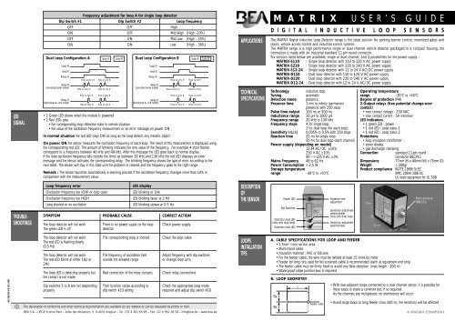
LEDSIGNALDual Loop Configuration AFrequency adjustment for loop A for single loop detectorDip Switch #1 Dip Switch #2 Loop frequencyLoop ALoop BRelay ARelay B(non-directional mode)Relay B(directional A— B mode)OFF OFF HighON OFF Mid High [High –20%]OFF ON Mid Low [High – 25%]ON ON Low [High – 30%]Pulse on entry BPulse on entry APulse on entry BPulse on entry ALoop APulse on exit BPulse on exit APulse on exit BPulse on exit ADual Loop Configuration BLoop B Loop A Loop BLoop ALoop BRelay ARelay B(non-directional mode)Relay B(directional A— B mode)• 1 Green LED shows when the module is powered• 2 Red LEDs give• the corresponding loop detection state in normal situation• the value of the oscillation frequency measurement or an error message on power ONIn normal situation the red LED stays ON as long as the loop detects any metallic object.Pulse on entry BPulse on entry APulse on entry BPulse on entry APulse on exit BPulse on exit APulse on exit BPulse on exit AOn power ON the sensor measures the oscillation frequency of each loop. The result of this measurement is displayed usingthe corresponding red LED. The amount of blinking indicates the tens value of the frequency. For example 4 short flashescorrespond to a frequency between 40 kHz and 49 kHz. After this message the LED goes back to normal display.If the loop oscillation frequency falls outside the limits set between 20 kHz and 130 kHz the red LED displays an errormessage and the sensor activates the corresponding relay. The blinking frequency shows the type of error according to thenext table. The sensor will stay in this state until the problem is cleared and the frequency goes to the right range.Remark : The sensor launches automatically a learning process if the oscillation frequency changes more than 10% incomparison with the measurement value.APPLICATIONSTECHNICALSPECIFICATIONSM A T R I X USER’S GUIDED I G I T A L I N D U C T I V E L O O P S E N S O R SThe <strong>MATRIX</strong> Digital Inductive Loop Detector range is the ideal solution for parking barrier control, motorized gates anddoors, vehicle access control and industrial control systems.The <strong>MATRIX</strong> range is a high performance single or dual channel vehicle detector packaged in a compact housing, theconnection is made with an industrial standard 11-pin round connector.Six versions listed below are available, single or dual channel, and 3 possibilities for the power supply :<strong>MATRIX</strong>-S110 : Single loop detector with 110 to 120 V AC power supply<strong>MATRIX</strong>-S220 : Single loop detector with 220 to 240 V AC power supply<strong>MATRIX</strong>-S12-24 : Single loop detector with 12 to 24 V AC/DC power supply<strong>MATRIX</strong>-D110 : Dual loop detector with 110 to 120 V AC power supply<strong>MATRIX</strong>-D220 : Dual loop detector with 220 to 240 V AC power supply<strong>MATRIX</strong>-D12-24 : Dual loop detector with 12 to 24 V AC/DC power supplyTechnologyinductive loopTuningautomaticDetection mode presencePresence time 1 min to infinity (permanentpresence) with 250 stepsPulse time output 100 ms or 500 msInductance range 20 µH to 1000 µHFrequency range 20 kHz to 130 kHzFrequency steps 4 for single loop2 for dual loop (for each loop)Sensitivity (ΔL/L) 0.005% to 0.5% with 250 stepsReaction time 25 ms for single loop50 ms for dual loop (each channel)Power supply (depending on model)12-24 AC/DC ±10%230 V AC ±10%90 -----> 125 V AC ± 0%Mains Frequency 48 to 62 HzPower Consumption < 2.5 WStorage temperaturerange–30°C to +70°COperating temperaturerange–30°C to +40°CDegree of protection IP402 Output relays (free potential change-overcontact)• max contact voltage : 230 VAC• max contact current : 5A (resistive)LED indicators• 1 green LED : power• 1 red LED : Loop status 1• 1 red LED : Loop status 2Protections• loop insulation transformer• zener diodes• gas discharge clampingConnectionstandard 11-pin roundconnector 86CP11Dimensions77mm (H) x 40mm (W) x 75mm (D)Weight< 200grProduct compliance R&TTE 1999/5/ECEMC 2004/108/ECUL listed equipment for UL 508TROUBLE-SHOOTINGSLoop frequency errorOscillation frequency too LOW or loop openOscillation frequency too HIGHLoop shorted or no oscillationSYMPTOMThe loop detector will not workThe green LED is offPROBABLE CAUSELED displayLED blinking at 1HzLED blinking faster at 2 HzLED blinking slower at 0.5 HzThere is no power supply to the loopdetectorCORRECT ACTIONCheck power supplyDESCRIPTIONOFTHE SENSORPower LEDDip SwitchesDetection state LED(only with dual loop)Detection state LEDPresence timeadjustmentSensitivity adjustmentpotentiometer(only with dual loop)Sensitivity adjustmentpotentiometerMain connector(86CP11)42-0570-V1 01/08The loop detector will not workThe red LED is flashing slowly(0.5 Hz)The loop detector will not workThe red LED blinks at either 1Hz or2HzThe loop LED is detecting properly butthe contact is not madeDip switches 5 to 8 are not respondingproperlyThe corresponding loop is shortedThe frequency of oscillation fallsoutside the allowed rangeBad connection of the relay contactsTheir function varies according todip switch #10 settingCheck the loop cableAdjust frequency with dip switchesor change loop turnsCheck relay connectionsCheck the appropriate loop moderequired and adjust dip switch #10The declaration of conformity and other technical documentation are available on our website or can be requested by phone or mail.<strong>BEA</strong> S.A – LIEGE Science Park – Allée des Noisetiers, 5 B-4031 Angleur – Tel. +32 4 361 65 65 – Fax +32 4 361 28 <strong>58</strong> – info@bea.be – www.bea.beLOOPSINSTALLATIONTIPSA. CABLE SPECIFICATIONS FOR LOOP AND FEEDER• 1.5mm 2 cross section area• Multi-strand cable• Insulation material : PVC or Silicone• For the feeder cable, the wire must be twisted at least 15 times by meter• Feeder for long runs used for foil screened cable is recommended (earth at equipment end only)• The feeder cable must be firmly fixed to avoid any false detection (max length : 100 m)• Waterproof cable junction box is requiredB. LOOP GEOMETRYLEaEbFeeder cable• With two adjacent loops connected to a dual channel sensor, it is possible forthese loops to share a common slot, if so required.As the channels are multiplexed, no interference will occur• Avoid large loops or long feeder (max 100 m), the sensitivity will be affected
C. DETERMINATION OF THE NUMBER OF LOOP TURNSWARNING :For conformity reasons, in any situation, the antenna factor defined as the loop surface multiplied by the number of turnsshould not exceed NA = 20D. DIP SWITCHESAfter each dip switch change the sensor launches a learning processDip Switch #1Frequency Adjustments of Loop AFor example, if L=2m, Ea=1m and the number of turns=4, then the NA = 2x1x4 = 8 < 20.Dip Switch #2Frequency Adjustments of Loop A (with single loop) or Loop B (with dual loops)Find hereafter the recommended values for the turns :Dip Switch #3Relay configuration : active or passive.WIRINGADJUSTMENTS4Area Number of turns< 3 m 26 - 10 m 2 23 - 5 m 23D. SLOT DEPTHLoopsealantWARNING : Do not remove the grease on the connector's pinsUL REQUIREMENT : The unit has to be mounted on a suitable UL recognized SWIV2 Relay SocketRelay socket suggestedreferences :• OMRON PF113A-D• LUNDBERG R11• MAGNECRAFT 70-465-1• IDEC SR3P-05C• ERSCE ES11• CUSTOM CONNECTORCORPORATION OT11A. THE 3 CONFIGURATIONS• Configuration # 1 : single loop detector (<strong>MATRIX</strong>-S)• Configuration # 2 : dual loop detector in independent mode (<strong>MATRIX</strong>-D with dip switch #10 OFF)• Configuration # 3 : dual loop detector in combined mode (<strong>MATRIX</strong>-D with dip switch #10 ON)B. POTENTIOMETERSPRESENCE TIME1 min 10 min1 HMin2 HMax5 HInfinity 20 H30 - 50 mm dependingon cable turns numberClean and dry slots priorto inserting cableSENSITIVITY0.5% 0.44%0.34%Min0.25%Max0.18%0.005% 0.1%Pin 1 : Power supplyPin 2 : Power SupplyPin 3 : Relay B (NO)Pin 4 : Relay B (COM)Pin 5 : Relay A (NO)Pin 6 : Relay A (COM)Pin 7 : Loop A (<strong>MATRIX</strong> S)Pin 8 : Loop common and earthPin 9 : Loop B (<strong>MATRIX</strong> D)Pin 10 : Relay A (NC)Pin 11 : Relay B (NC)• A potentiometer for adjustment of the maximum duration of a presence detection :from 1 min to infinity• A potentiometer for adjustment of the linear sensitivity (Δf) for the loop A :from 0.005% to 0.5 %• A potentiometer for adjustment of the linear sensitivity (Δf) for the loop B :from 0.005% to 0.5 %DS#1DS#2DS#3DS#4DS#5Dip Switch #4 Automatic Sensitivity Boost (ASB option) [recommended for better trucks detection] :During a detection the sensitivity increases automatically to 8 times the preset sensitivity given by thesensitivity potentiometer adjustment. It is limited to the maximum sensitivity (Δf = 0.005%).It goes back to the preset value after detection stops.Dip Switch #5Dip Switch #6Dip Switch #7Dip Switch #8Dip Switch #9Dip Switch #10OFFActive modeASB OFFRelay A function : presence or pulse (not used with dual loop in combined mode)Relay A Pulse type : entry or exit (used only at pulse function)or Relay B mode (with dual loop in combined mode) (see next drawing)• non-directional :The relay B provides a pulse according to the dip switches #7 and #8 setting.• directional A— B :The relay B provides a pulse only if the loop A is detecting before the Loop B.The detection takes place according to dip switches #7 and #8 logic.Warning : During the detection, the 2 loops have to detect simultaneously for a short period to beable to determine the movement direction. During loop installation make sure the 2 loops are closeenough to each other to ensure a common detection (typical 1m).Relay B function : presence or pulseor loop selection for relay B pulse : pulse on Loop B or pulse on Loop A (used with dual loop incombined mode)Relay B Pulse type : entry or exit (used only at pulse function)Pulse duration for both relays (used only at pulse function): 100 ms or 500 msDual loop mode : independent or combined A— B (not used with single loop)Configuration #1Single loopSee next tableONPassive modeASB ONRelay A : Relay A :Presence on loop A Pulse on loop AConfiguration #2Dual loop in independent modeOFFONHigh (loop A) Low (loop A)[High –30%]High (loop B) Low (loop B)[High –30%]Active modeASB OFFPassive modeASB ONRelay A : Relay A :Presence on loop A Pulse on loop AConfiguration #3Dual loop in combined modeOFFONHigh (loop A) Low (loop A)[High –30%]High (loop B) Low (loop B)[High –30%]Active modeASB OFFNot usedPassive modeASB ONNot usedC. RELAY CONFIGURATIONS (Dip Switch #3)The loop A activates the relay A and the loop B activates the relay B. With the dual loops in combined mode the relay Aprovides the presence detection and the relay B provides the movement directionDS#6Relay A : Relay A :Pulse on loop A Pulse on loop AentryexitRelay A : Relay A :Pulse on loop A Pulse on loop AentryexitRelay B : Relay B :non-directional directionalmodeA— B modeACTIVE MODE(dip switch #3 OFF)PASSIVE MODE(dip switch #3 OFF)DS#7Relay B : Relay B :Presence on loop A Pulse on loop ARelay B : Relay B :Presence on loop B Pulse on loop BRelay B : Relay B :Pulse on loop B Pulse on loop ADetectionNo DetectionCOMCOMNONCNONCCOMCOMNONCNONCDS#8DS#9Relay B : Relay B :Pulse on loop A Pulse on loopAentryexit100 ms 500 msRelay B : Relay B :Pulse on loop B Pulse on loop Bentryexit100 ms 500 msRelay B : Relay B :Pulse on loop Pulse on loopentryexit100 ms 500 msDS#10Not usedNot usedIndependent modeCombined modeIndependent modeCombined mode