Climate protection needs energy efficient data centers - Stulz GmbH
Climate protection needs energy efficient data centers - Stulz GmbH
Climate protection needs energy efficient data centers - Stulz GmbH

Create successful ePaper yourself
Turn your PDF publications into a flip-book with our unique Google optimized e-Paper software.
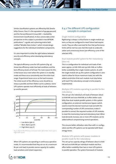
Energy Efficiency in the Data CenterSimilar classification systems are offered by IEEE (AvailabilityClasses, Class V is the equivalent of 99.999 percent)and the Harvard Research Group (AEC = AvailabilityEnvironment Classification). A clear, concise <strong>data</strong> centerperspective on this subject is provided in two BITKOMpublications 17 : a guide and a planning matrix bothentitled “Reliable Data Centers”, which include designsuggestions for the individual installation components.It is also important to strike the right balance betweensecurity and efficiency when developing redundancyconcepts.The typical efficiency curve for UPS systems (Fig. 14)shows low efficiency under low load conditions and thebest efficiency levels at full load. The main reason for thisis that losses occur even when the system is in standbymode and these occur consistently over the entire loadrange. Proportional losses occur as the load increases.The initial ascent of the efficiency curve should be assteep as possible and then flatten out to a plateau. SomeUPS systems operate most <strong>efficient</strong>ly at loads of between50 and 80 percent.Efficiency [%]97%96%95%94%93%92%91%0 20 40 60 80 100Load [%]Low Mains (380 V)Nom. Mains (400V)High Mains (415 V)Fig. 14: Typical UPS efficiency curve (Low mains: 380 V, Nom. mains: 400 V,High mains: 415 V)When UPS systems are operating in continuous operationmode, it is recommended that they are run at a maximum80 per cent load, to provide reserve capacity for suddenload variations and instant expansion.6.4.2 The different UPS configurationconcepts in comparisonSingle module configurationRightsizing is always a critical factor in single module systems,as they are configured to meet future load requirements.They are often oversized for fear that performancelimits will be met too soon. But this leads to underutilizationand unnecessary losses (see efficiency curve of theselected UPS).Dual module parallel system for N+1 redundancy(also 1+1)This is a configuration for individual unit loads of betweenapprox. 20 kVA /kW and 250 kVA /kW, as it offersbetter availability than single module systems. As withthe single module set-up, this system configuration is alsosized to allow for future maximum loads, but with theadded constriction that each module must stay below50% load if the redundancy concept is to be properlyimplemented.Multiple UPS modules operating in parallel for N+1redundancyThis set-up is for individual unit loads of between about20 kVA/kW and 1000 kVA/kW, as it offers better scalabilitythan dual module parallel systems. In this systemconfiguration, an external maintenance bypass switch,sized to meet the desired maximum load and with thecorresponding number of UPS connections, makes itpossible to connect the required number of UPS modulesto meet the momentary load and redundancy level. Whenload demands increase, one or more UPS modules can beadded without compromising normal operations.This ensures better utilization rates than with 1+1 configurationand the UPS systems can be operated with fewer<strong>energy</strong> losses.Modular UPS systems with power modules inparallel mode for N+1 redundancyThis set-up has capacity ratings of between about 10 kVA/kW and 200 kVA/kW per individual module and thusoffers better scalability than two or more UPS systemsin parallel operation. The system framework of modular29