D2600 Relays.pub - LGM Products Ltd
D2600 Relays.pub - LGM Products Ltd
D2600 Relays.pub - LGM Products Ltd
- No tags were found...

You also want an ePaper? Increase the reach of your titles
YUMPU automatically turns print PDFs into web optimized ePapers that Google loves.
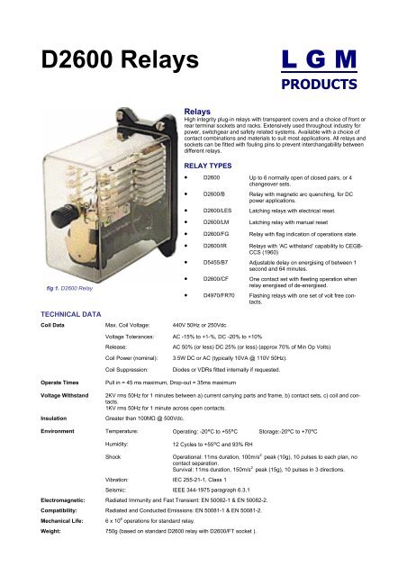
<strong>D2600</strong> <strong>Relays</strong>L G MPRODUCTS<strong>Relays</strong>High integrity plug-in relays with transparent covers and a choice of front orrear terminal sockets and racks. Extensively used throughout industry forpower, switchgear and safety related systems. Available with a choice ofcontact combinations and materials to suit most applications. All relays andsockets can be fitted with fouling pins to prevent interchangability betweendifferent relays.RELAY TYPES• <strong>D2600</strong> Up to 6 normally open of closed pairs, or 4changeover sets.• <strong>D2600</strong>/B Relay with magnetic arc quenching, for DCpower applications.• <strong>D2600</strong>/LES Latching relays with electrical reset.• <strong>D2600</strong>/LM Latching relay with manual reset• <strong>D2600</strong>/FG Relay with flag indication of operations state.• <strong>D2600</strong>/IR <strong>Relays</strong> with ‘AC withstand’ capability to CEGB-CCS (1960)• D5455/B7 Adjustable delay on energising of between 1second and 64 minutes.fig 1. <strong>D2600</strong> Relay• <strong>D2600</strong>/CF One contact set with fleeting operation whenrelay energised of de-energised.• D4970/FR70 Flashing relays with one set of volt free contacts.TECHNICAL DATACoil Data Max. Coil Voltage: 440V 50Hz or 250VdcVoltage Tolerances: AC -15% to +1-%, DC -20% to +10%Release:Coil Power (nominal):Coil Suppression:AC 50% (or less) DC 25% (or less) (approx 70% of Min Op Volts)3.5W DC or AC (typically 10VA @ 110V 50Hz).Diodes or VDRs fitted internally if requested.Operate TimesVoltage WithstandInsulationPull in = 45 ms maximum, Drop-out = 35ms maximum2KV rms 50Hz for 1 minutes between a) current carrying parts and frame, b) contact sets, c) coil and contacts.1KV rms 50Hz for 1 minute across open contacts.Greater than 100MΩ @ 500Vdc.Environment Temperature: Operating: -20°C to +55°C Storage:-20°C to +70°CHumidity:12 Cycles to +55°C and 93% RHShockVibration: IEC 255-21-1, Class 1Operational: 11ms duration, 100m/s 2 peak (10g), 10 pulses to each plan, nocontact separation.Survival: 11ms duration, 150m/s 2 peak (15g), 10 pulses in 3 directions.Seismic: IEEE 344-1975 paragraph 6.3.1Electromagnetic: Radiated Immunity and Fast Transient: EN 50082-1 & EN 50082-2.Compatibility: Radiated and Conducted Emissions: EN 50081-1 & EN 50081-2.Mechanical Life: 6 x 10 6 operations for standard relay.Weight: 750g (based on standard <strong>D2600</strong> relay with <strong>D2600</strong>/FT socket ).
DIMENSIONSfig 2. Relayoutline drawing(shown with RTsocket and35mm rack).CONTACT ARRANGEMENTSfig 3. Availablecontactarrangements(Keycodes). Contactpin numbers are aviewed on the rearof therelay.NOTE: Only the most popular arrangements are shown above, other arrangements are available on request. Changeover contacts arebreak-before-make on above codes. Make-before-break keycodes are also available but the connections are different to standardchangeovers. Contacts will be supplied in silver unless specified otherwise.CONTACT RATINGSSilver ContactsThese are standard contacts for most applications. Each contact pair is capable of switching the loads given in the table but subject tothe Relay Total Current Carrying Capacity as defined below.DC LOADS (Non-inductive)250Vdc@ 0.5A max130Vdc @ 0.5A max85Vdc @ 1.5A max50Vdc @ 5A max35Vdc @ 7A maxFor intermediate values interpolate betweenthe nearest two levels.AC LOADS250Vac @ 10A max.With a power factor of not less than 0.8.For more inductive loads multiply the max. current (10A) bythe power factor to determine the allowed switching current.Palladium CopperThese contacts are virtually tarnish free in normal atmospheres. They have a smaller contact dome to provide higher contact pressureand more wiping action. Mainly used for low energy switching (typically 5V at 10mA) but they will handle up to 2A (subject to a maximumof 40W or 4VA). Specified by adding PdCu to the relay description code.Silver Cadmium Oxide (D54X)These contacts are fitted as standard with magnetic blow-outs to provide maximum resistance to arcing for heavier inductive DCloads. They will break DC inductive loads of up to 10A at 120V or 5A at 250V, but it is recommended that two contacts are used inseries for highly inductive loads above 200Vdc. For optimum arc quenching, always connect the more positive supply to the highestnumber contact of a pair. For changeover contact this applies to the pair breaking the highest or most inductive current. Silver CadmiumOxide contact with magnetic blow-out are specified by adding a ‘B’ to the relay descriptive code. Silver Cadmium Oxide mayalso be used without blow-out magnets for AC loads and for intermediate DC loads (add D54X to relay descriptive code). Switchingcapacity is the same as for silver contacts but contact life will be improved due to the greater arc resistance of these contacts.
ARC SUPPRESSIONBlow-out magnets are fitted as standard to relays with Silver Cadmium Oxide contacts. They may also be fitted with other contactmaterials where arc quenching is required to improve contact life. External arc suppression (e.g. diodes or VDR’s) should also be consideredfor inductive loads where contact arcing is likely to occur.RELAY TOTAL CURRENT CARRYING CAPACITYTo limit internal heating, relays are subject to a maximum overall relay current calculated as follows:I 12+ I 22……………………………….I n 2 ≤100.Where I 12 etc are the currents carried simultaneously by individual contacts. Where possible the current should be shared betweenthe two contact stacks for optimum heat distribution within the relay. Individual contact loading must not exceed the specified limit forthe contact material.ELECTRICAL (CONTACT) LIFEFor light loads the contact life will approach the mechanical life of the relay. This will be reduced in more arduous duty depending onload (particularly breadki8ng o heavy inductive DC loads), frequency and number of operations and local environmental conditions.Greater reliability and contact life can be obtained by sharing heavy loads between contact and by using blow-out magnets whereappropriate. Typical contact lives for heavy resistive loads (under laboratory conditions) are:>10 6 operations @ 4A and 127Vdc for all contact types with blow-out magnet fitted.>10 5 operations @ 7A and 120Vdc for silver cadmium oxide or silver contacts with blow-out magnet fitted.>3x10 4 operations @ 10A and 120Vdc for silver cadmium oxide contacts with blow-out magnet fitted.NOTE: The information given above is for guidance only and derives from test on contacts used under ‘normal’ operating conditions.For abnormal and critical applications, tests should be carried out to confirm suitability.Latching <strong>Relays</strong>LATCHING RELAYS WITH ELECTRICAL RESETExternally identical to the standard <strong>D2600</strong> relay and compatible with the standard sockets and racks. Contact materials and types areas the standard relay. Blow-out magnets are available on relays fitted with N/O or N/C contacts. All types require a minimum pulse of80ms to operate the relay and 100ms to reset. Coils are available for operation on DC voltages between 6V and 250V with AC operationprovide via bridge rectifier. Coils can be wired as circuit A (internally commoned on one side, three wire –see fig 4) or circuit B(independent, four wire—see fig 5). Suppression diodes (specify polarity when ordering) or VDR’s are available on request.figs 4 & 5. InternalRelay wiring.<strong>Relays</strong> are shownin the detachedstate with nopower to eithercoil. LES typesare shown. LE issimilar but withoutcontacts in theoperate coil .fig 4. Circuit A wiring (3-wire). Standard Keycodesavailable 5, 11, 16, 20, 23, 25 & 30fig 5. Circuit B wiring (4-wire). Standard Keycodesavailable 4, 10, 15, 19, 22 & 29<strong>D2600</strong>/LES & <strong>D2600</strong> LES/B - Suicide Contacts on both coils.Bi-stable relay with suicide contacts protection for both operate and reset coils. Coils are rated for intermittent operation and the specifiedminimum voltage must be applied to ensure the relay changes state and breaks the associated suicide contact. Current drain fromthe supply is limited to approximately 100ms from application to either coil. Supply must not be applied to both circuits simultaneouslyor the relay may malfunction or overheat.Provided with up to five externally available N/O or N/C contacts (four for Circuit B wiring) or up to three C/O contacts. In addition therelay will have a N/O contact on the main contact stack to ’arm’ the rest coil and a separate N/C contact on the latch assembly to disarmthe operate coil. These additional contacts should not be included when determining the keycode of the relay, which refers to theexternally available contacts only.<strong>D2600</strong>/LE & <strong>D2600</strong>/LE/B - Suicide Contacts on Reset coil onlySimilar to the <strong>D2600</strong>/LES relay but the suicide contact is omitted from the operate coil circuit. The operate coil can be continuouslyenergised but supply must not be applied to both circuits simultaneously or the reset coil may overheat.
LATCHING RELAYS WITH MANUAL RESETLatching relays type <strong>D2600</strong>/LM are externally similar to the <strong>D2600</strong> relays and are compatible with standard sockets and racks. Contactmaterials and types are the same as the standard relay and the full number of contacts and blow-outs magnets can be fitted. On energising,a spring loaded latch arm moves across the armature, thereby locking it in the energised position when the coil is de-energised.The latching arm can be reset by rotating the red knob on the front of the relay and is coloured red to give clear indication of relaystate.fig 6. <strong>D2600</strong>/LM.Front view ofLatching Relaywith manual reset.<strong>Relays</strong> with Timing FunctionsDELAY OPERATION TIMING RELAY - D5455/B7Solid state delay-to-operate timer relay with delays of up to 64 minutes in six bands (factory pre-set, please specify band when ordering),mounted in a <strong>D2600</strong> case. LED indication of when unit is timing.Supply 12V, 24V, 36V, 50V, 100V or 240V (+10% -20%)DC or AC(50Hz to 110Hz). Full-wave rectified(internally)Output contacts Standard contact arrangement is two N/O plus twoN/C silver Contacts. Other materials and contactcombinations available on request. Blow-out magnetscannot be fitted to this relay.Repetitive Accuracy +/- 0.5% at constant operating conditionsAmbient Temp.RangeFouling pinsTiming Ranges-30°C to +55°CA number of fouling pins (U to Z, determined bysupply voltage) are available in addition to the standardrange.DELAYLINK1-4 seconds4-16 seconds16-64 seconds1-4 minutes4-16 minutes16-64 minutesABCDEFfig 7. D4544/B& Delay operation timing relay.FLEETING CONTACT RELAY - <strong>D2600</strong>/CF**One set of contacts operates for a brief time when the relay is energised, de-energised or both, irrespective of how long the main coilremains energised. The fleeting contacts can be applied as normally or normally closed with changeover contacts available on request.Pulse LengthRecovery TimeSupply VoltagesFleeting contact ratingNon-Fleeting ContactsFleeting contacts operate for between 100 to 300ms (not adjustable)Less than 500ms24V, 50V, 100V or 240V (+10% -20%) DC or AC(50Hz to 110Hz). Full-wave rectified (internally)110Vac 5A (non-inductive). 110Vdc 30W (non-inductive)Blow out magnets are not available. Can be supplied in all available materials to the followingKeycodes:FLEETING CONTACTS ON NON-FLEETING CONACTS KEYCODESRELAY PINSAVAILABLE11 & 1312 & 144, 10, 15, 19, 22 & 295, 11, 16, 20, 23, 25 & 30Fouling PinsThis relay can be fitted with the full range of fouling pins.
FLASHING RELAY—D4970/FR70A self-contained pulse unit with a PCB mounted control circuit and one set of volt free changeover contacts, mounted in a <strong>D2600</strong> case.Two pre-set potentiometers are provided to set the pulse rate and the on/off ratio. If the supply is disconnected the relay return to thede-energised state i.e. with contacts 3 and 5 closed to maintain a path for the alarm condition.Pulse Rate Typical adjustment range between 60 and 180pulses/min.On-Off Ratio Typical Adjustment Range between 3:1 and 1:3.Supply Voltages24VDC (or 50VAC)50VDC (or 110VAC)110VDC (or 250VAC)NB The relay is diode protected against supplyreversal (pin 1 positive for DC supplies)Output ContactsFouling pinsSingle pole changeover. Silver Cadmium Oxide(with blow-out magnets).The standard range of fouling may be used withthe exception of: 6, 12, 18, 24, 30, 36, 42, 48,60, 66, and 72.fig 8 D4970/FR70Flashing relayRelay SocketsSockets are rated at 440Vac and the RT and FT types are the subject of Small Components Certificates 100A and 156A. Anti-trackingbarriers are provided between the socket tags, but the leads should be sleeved for voltages above 250V.The sockets should be mounted so that the relay contacts are uppermost as shown in fig 9 . For most applications the relays may bemounted close together. Where they are likely to be energised for long periods (and particularly if the contacts are also carrying heavycurrents) a gap must be left between sockets to allow air to circulate freely. A spacing of 10mm between sockets has been found to bethe optimum for relays at maximum dissipation. Adequate heat transfer methods/ventilation must be provided for enclosed cabinets.<strong>D2600</strong>/ST and <strong>D2600</strong>/LTThese sockets are designed for slide mounting on the racks (see fig 8). The ST & LT types have solder terminals and can be fitted toeither rack type (10 or 35mm). They can also be mounted directly to a panel using the inner M4 fixing holes (84 centres) but the panelmust be insulated from the terminals for the ST and a cut out provided for the terminals for the LT. The outer fixing holes (105 centres)can be used for mounting both type to plan rails if required.<strong>D2600</strong>/RTThe RT socket has rear terminal blocks and can be slide mounted to the 35mm rack. Terminal screws are M4 and there is an 8mmspacing between barriers to accommodate tags or wires. The inner fixing holes are not available for panel mounting this socket but theouter holes may be used for mounting to plain rails if required.<strong>D2600</strong>/FTThe socket is similar to the RT but has front mounted terminals. It can be directly mounted to a panel using the two diagonal M5 fixingholes. The FT socket can be slide mounted to the 35mm rack but their wider profile limits the number than can be accommodated onthe single rack.DIMENSIONSfig 9 Dimensions (mm) of available sockets
Mounting RacksWhere there is adequate ventilation and the relays are not permanently energised, racks can be populated with up to the maximumnumber of relays stated below. Where the relays are permanently energised or carrying heavy current (particularly if mounted in anenclosed cabinet), additional spacing of approximately 10mm should be allowed between relays. Where two dimensions are given forC in the table, there is an additional cross rail fitted which must be retained to prevent bowing of the channels. The relay spacing musttherefore be calculated separately for the two sections.DIMENSIONSMAX NOOFRELAYSAmmBmmCmmfig 8 Mounting Rack dimensions (mm)1234567891011121312818023228533738944149354559764970175310315620826031136441646852157262467672852104156208260312208+156208+208260+208260+260312+260312+312364+312Rack Part No: D2630 Accepts Socket Types: ST & LT Depth D: 19Rack Part No: D4532 Accepts Socket Types: ST, LT, RT & FT (accepts FT with reduced number of relay) Depth: 35Multi-Contact Relay D3300Based on the <strong>D2600</strong> Relay but intended for applications where a larger number of contacts are required or where an open style, directlywired unit is preferred. A single fixing bracket is factory fitted as standard in the position shown. If request this can be factoryfitted facing inwards or on the opposite side of the relay. Two brackets can also be factory fitted (one either side) for applicationswhere shock or vibration may be encountered. The D3300 Relay can be supplied as a latching relay with electrical reset, similar to the<strong>D2600</strong> version.Supply VoltageWeightOutput ContactsDC Supplies up to250VdcAC supplies up to250VacAC Supplies above250VacUp to 440VAC or 250VDC. Operation on AC voltages is limited to the number of contacts specified below butrectifiers can be fitted to allow a DC relay to operate on an AC supply. Coil suppression diodes of VDRs canalso be fitted.570g (with maximum number of contacts)All the standard <strong>D2600</strong> contact keycodes, materials and blow-out magnets can be used. Additional contactsets can be fitted to the D3300 Relay up to the maximum specified below but blow-out magnets (if fitted) willonly be effective on the contact sets nearest to the coil, up to a maximum of four C/O or six N/O or N/CUp to six C/O or ten N/O or N/C sets may be fitted on each relay.Up to six C/O or ten N/O or N/C sets may be fitted on each relay but if a total of more than six contacts setsare fitted then no more than five of the sets can be C/O or N/C contacts (due to the extra armature loading ofthese types).Up to four C/O or six N/O or N/C sets may be fitted on each relay.DIMENSIONSFig 9 D3300relaydimensions(mm)CONTACTS2 M or B2 C/O4 M or B6 M or B4 C/O8 M or B6 C/O10 M or BHEIGHT647075858595101106
Order CodesThe order code for any given relay consists of the following elements:Relay Type/Variants/Flag/Contact Materials/Contact Arrangement/Fouling Pins/Coil VoltageRelay TypesVariantsFlagContact MaterialsContactArrangementFouling PinsCoil Voltage<strong>D2600</strong>, D,3300. D5455/B7, D4970/FR70Unspecified - Standard RelayLES, LE - Latching relay, electrical resetLM - Latching relay, mechanical resetTC - Twin CoilCFab - Fleeting contacta = M (N/O contacts) B (N/C contacts) C (C/O contacts)b = E (Fleeting on energising), D (Fleeting on de-energising) or ED (Both)Unspecified - Standard relay without flag.FG - FlagUnspecified = SilverPdCu = Palladium copperB = Silver cadmium oxide with magnet blow-outD54X - Silver cadmium oxide without magnetic blow-out## - Keycode from relay data sheet or other contact arrangement to special orderUnspecified—No fouling pins fittedFP## - Fouling pin codeCoil Voltage (DC or AC with frequency)RELAY SOCKETS<strong>D2600</strong>/Termination/Fouling PinsSocket TypeTerminationFouling Pins<strong>D2600</strong>ST - Short TagLT - Long TagRT - Rear TerminalFT - Front TerminalUnspecified - No fouling pins fittedFP## - Fouling pin codeNOTES1. <strong>Relays</strong> and sockets are allocated a unique computer code (e.g. 2LD265008(, which will be quoted on our quotations and invoices.This will be marked on the relay as a shortened reference code (e.g. 6L5008). These codes must be quoted wheneverpossible to ensure that the correct relay is supplied, particularly for replacement of spares orders. If fouling pins are specified,the FP code will be marked on both the relay and the socket.2. The order of the descriptive elements in the code may not always be exactly as shown above. This is not critical as long as allrelevant elements are included. In certain cases, two or more elements from one category may be included.3 Other features not covered by the relay code system should be included in the relay description. E.g. Diodes of VDRs to befitted across coils (polarity of coil supply must be included for diodes e.g. positive to pin 1).<strong>LGM</strong> PRODUCTS LTDUNIT 18 RIVERSIDE INDUSTRIAL ESTATEFARNHAMSURREY GU9 7UGUNITED KINGDOMTEL +44 (0) 1252 725257FAX +44 (0) 1252 727627E-mail Sales@Lgmproducts.comwww.Lgmproducts.com