To View Product Operation Manual. - The Swimming Pool Store
To View Product Operation Manual. - The Swimming Pool Store
To View Product Operation Manual. - The Swimming Pool Store

You also want an ePaper? Increase the reach of your titles
YUMPU automatically turns print PDFs into web optimized ePapers that Google loves.
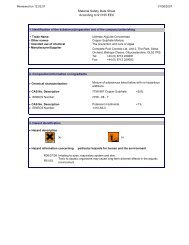
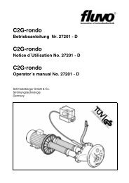
!WARNING1 . Important Safety InstructionsWhen installing and using this electrical equipment,basic safety precautions should always be followed,including the following:!A. READ AND FOLLOW ALL INSTRUCTIONS.!B. WARNING : <strong>To</strong> reduce the risk of injury, do notpermit children to use this equipment unless theyare closely supervised at all times. Failure to adhereto this and all other warnings could result in seriousinjury or death. !C. A licensed electrician is required for all wiringconnections.D. TO REDUCE RISK OF ELECTRICAL SHOCK,connect all ground wires to grounding terminal locatedin the control box. Use no smaller than a No. 12!AWG (3.3 mm 2 ) wire.!E. TO REDUCE RISK OF ELECTRICAL SHOCK, abonding connector is provided on the motor for bondingof local ground points such as water pipes, metalladders/handrails, or other metal within 5 feet of thepool. All local ground points should be bonded with aNo. 8 AWG (8.4 mm 2 ) wire. Never use gas piping asan electrical ground.F. All electrical equipment should be installed inaccordance with local codes.2. Introduction and Planning!!G. DO NOT store or use gasoline or other flammablevapors or liquids in the vicinity of this equipment. DONOT store pool chemicals near the equipment.H. DO NOT remove any safety alert labels suchas DANGER, WARNING, or CAUTION. Keep safetyalert labels in good condition and replace missing ordamaged labels.I. Keep and read all equipment manuals. Adhere to!all of their instructions.!J. WARNING : Stay alert, watch what you are doingand use common sense. DO NOT use unit if you aretired and/or exhausted. Do not use unit while under!the influence of drugs, alcohol, or any medication.K.! WARNING : Consult your physician beforeexercising with the BADUJET or using the massage!hose.!L. WARNING : DO NOT use or operate theBADUJET if the rectangular (or optional doubleround) anti-entrapment cover is missing, broken or loose.M. SAVE THESE INSTRUCTIONS! Refer tothem frequently and use them to instruct third partyusers.<strong>The</strong> BADUJET is normally incorporated into theoriginal pool design. However, it can be added to anypool at a later date.<strong>The</strong> BADUJET has no protruding parts, ensuringthe pool user's safety. It is very compact and installsat minimal cost.<strong>The</strong> BADUJET can be installed in any size pool.We suggest a minimum pool size of 7 ft. wide, 14 ft.long and 3 1/2 ft. deep in order to swim. Most prefer16 ft. in length or longer. <strong>The</strong> extra length allowsthe swimmer to comfortably drift back and swim upstream.Consult local codes for minimum distance betweenpump and pool. Locate pump as close to theBADUJET as practical.Use at least 4" pipe when distance between jethousing and pump is 30 ft. or less and 6" pipe forruns longer than 30 ft.<strong>The</strong> 4 HP, self-priming, plastic pump has a singlephase motor with thermal overload (no motorstarter required). <strong>The</strong> 4 HP single phase motordraws a maximum of 19.4 amps at 230 V. <strong>The</strong> unitrequires a minimum circuit of 30 amps. Install a40 amp breaker to avoid nuisance tripping whenthe pump is turned on and off frequently. <strong>The</strong>starting current of the 4 HP motor can reach upto 6 times the running currents. (Three phasemotor draws a maximum of 12.8 amps @ 230 Vand 6.4 amps @ 460 V.)3. Plumbing for!<strong>The</strong> BADUJET assembly package contains allnecessary parts for the installation of the unit intoconcrete, gunite, liner or fiberglass pools.!! CAUTION : All necessary screws and bolts includedwith the BADUJET are stainless steel or plastic. ALLscrew!threads and threaded inserts are METRIC!ONLY METRIC screws, ! bolts and nuts may beused! <strong>The</strong> one exception is the connecting threadfor the intake and delivery connections on theBADUJET and pump housing. <strong>The</strong>se are 3" NPTthreads and 4" slip. Use only 4" slip for BADUJET.! CAUTION : <strong>The</strong> adapters on the housing arefactory mounted and should never be removed.Removal ! of these adaptors will void warranty.! CAUTION : <strong>The</strong> pressure connection must belocated exactly ABOVE the suction connection.!! CAUTION : <strong>The</strong> center of the housing (the twonozzles) should be 10" BELOW water level formaximum ! efficiency. <strong>The</strong> air regulator should beapproximately 4" ABOVE the water level. (See fig. 1.)2
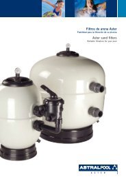
4. Concrete or Gunite InstallationA. Preplumb BADUJET Housing1. Install the two PVC SCH 80 couplings 110 mm/4”slip (#2a) on the PVC SCH 80 fittings 110 mm (#2)which are premounted on the jet housing.2. Install approximately 12" of 4" SCH 40 pipe to bothsuction and discharge couplings on the jet housing.NOTE: If plumbing exceeds 30' between jet housingand pump, increase pipe size to 6". Install a 6x4"reducing bushing as close to jet housing as possible.3. Install approximately 18" of 1/2" conduit to back ofjet housing. (Conduit connector part # 3).4. Install air control PVC hose (part # 7) and Y socket(part # 6) assembly to hose socket insert fittings (part# 4). Use hose clamps (part #8) to secure hose toinsert fitting.B. Mount the protective cover plate (part # 30) to jethousing using stud bolts M8x80 (part # 31). Tapeedge of cover plate to jet housing. <strong>The</strong> cover plateand stud bolts are solely used for installation and canbe discarded afterwards. Keep concrete out ofthreaded inserts and out of the inside of the housing.C. Place jet housing into reinforced steel. (See fig. 7.)Jet housing location is very important.1. Locate pressure connection exactly above the suctionconnection. Pressure and suction connectionsmust be exactly vertical or the rectangular cover willbe uneven in appearance.2. <strong>The</strong> center of the housing (the two nozzles) shouldbe 10" BELOW water level for maximum efficiency.Fig. 4 Template for installation in gunite orconcrete pools.3. Front edge of Jet housing should finish even withinside gunite wall. Make sure a V shaped groove isscraped out around the housing approximately 1 1/2"deep to allow marcite to seal against the housing.4. Recheck location of Jet housing when gunite isbeing applied. <strong>The</strong> force of the gunite may move thejet location.5. <strong>To</strong> avoid stress on the jet housing, we recommendthat the BADUJET housing be encased with guniteand at least 2 to 3 inches of the plumbing stub out iscovered with gunite. NOTE: Stress on the plumbingmay crack the BADUJET housing.D. Air regulator installation should be approximately4" ABOVE the water level.1. Air regulator holder (part # 9) and hose socketinsert fitting (part # 5) connect to PVC hose (part #7). Make sure air regulator holder face is taped overto prevent gunite from entering holder.2. Air regulator can be located in the tile line abovewater line or in the deck.E. Keep all parts not being used now in original box.<strong>Store</strong> in a safe place until needed.F. <strong>The</strong> following is a list of all parts that ARE NOTUSED IN A GUNITE INSTALLATION:1. Gasket w/knobs # 262. Clamping ring gasket # 273. Counter sunk bolt # 104. Washer M6 # 125. Nut M6 # 116. Counter sunk bolt # 98Fig. 5 BADUJET in concrete or gunite pool.1.7”0.5”oM8x40Air Line0.25”oWater Level14.00”o~10” ~4”M8x80PressureSuction40.3”oUnit housing
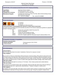
4a. Installing in existing gunite or concrete poolMaterials: 1 piece Plywood 2'x3'xI/4"8 Lag screws 1/4" x 1 1/2"(minimum)8 Plastic lag anchor shieldsStep 1. Carefully choose the location in whichBADUJET is to be installed; it should be a flatsurface with no or very little crown.With a concrete saw, cut out the outline of the sectionto be chiseled out with an air hammer or equal. Thishole should be 19" wide x 19" down from the waterline. <strong>The</strong> bonding rods on the cap of the pool shouldbe left intact, while all other steel rods should be cutback to clear the placement of the jet housing.Step 2. Taking the 2'x3'x1/4" plywood, set its top edgeeven to the cap of the pool wall. In some cases alarger piece of plywood may be needed to cover thehole completely. If plywood covers the hole, markthe water line on the plywood. From this line, layoutand drill holes in plywood for the air regulator, thefour BADUJET housing installation studs, and theeight 1/4" lag screws. NOTE: See fig. 5a for layoutmeasurements.Insert installation studs (part # 31) in jet housing; oneat the top, the bottom of the vertical center line andon each side on the horizontal center line. Placecover plate on studs covering the inside of the jethousing. Next place plywood on the studs and securewith washers and nuts.Now place this assembly into position in the pool walland align the water line marks. With a level onthe two horizontal studs, level the assembly andmark the 8 holes for the 1/4" lags. Remove assemblyand drill holes for lag anchors. Reposition theassembly and secure lags. It is best to check with alevel before tightening the lags down. Back fill andform the outside of pool wall.Step 3. Mix compound that is compatible and hasgood bonding characteristics to the pool wallcompound. Pour mixture into form. Use a mallet andlightly tap the front of formed assembly to settlemixture, and avoid any air bubbles in the pour. Itshould be filled to the top of the plywood. Let mixcure and then remove plywood form and cover plate.Drill out plastic lag anchors and feather in pool wallfinish. Replace tile and coping. Remove assemblystuds and install nozzle housing and anti-entrapment cover. (See sections 6 & 7.)Throughout the entire installation, make sure theplumbing connected to the BADUJET housing iswell supported. Unsupported plumbing will crack theBADUJET housing. <strong>To</strong> avoid stress on the plumbing,we recommend that the BADUJET housing beencased with gunite and at least 2 to 3 inches of theplumbing stub out is covered with gunite. Stress onthe plumbing may crack the housing.Fig. 5A Layout for installing in existing gunite or concrete pools.19”CapWater line19”2’10”3’5
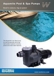
5. Liner and/or Fiberglass pool installation! CAUTION : Locate the pressure connection exactlyabove the suction connection. Pressure and suctionconnectors ! must be exactly vertical or the rectangularcover will be uneven in appearance.! CAUTION : Center of Housing (the two nozzles)should be 10" BELOW water level for maximum efficiency.!! CAUTION : Gasket with knobs (part # 26) goesBEHIND pool wall.!! CAUTION : Clamping ring gasket (part #27) goes inFRONT of pool wall. A good RTV silicone may be!used with gasket when mounting jet housing, but inmost cases is not necessary. Installer should decidewhether or not silicone is necessary.<strong>The</strong> template provided should be used to mark anddrill the holes as shown in fig. 6. For the air regulator,one 1/2" hole must be provided, preferably along thevertical axis, approximately 4" ABOVE the water line.For Liner pools only, two additional 1/4" holes needto be made on either side of the 1/2" hole. (See fig 6.)Use the two countersunk bolts M6 (part # 10), twonuts (part # 11), and two washers (part # 12) to fastenholder to wall with bolt heads on poolside and nutson backside. This will keep the holder attached topool wall for liner installation or replacement.NOTE: Gasket (part # 13) with larger holes on theoutside, fits over screw heads between inside of poolwall and liner. This gasket may be held in place withsilicone during liner installation.F. <strong>The</strong> list below shows all parts that ARE NOT USEDIN A FIBERGLASS/VINYL LINER INSTALLATION:1. Cover plate # 302. Stud bolt M8x80 # 313. Washer M8 # 324. Nut M8 # 3330 o0.25”o15 o1.7”Fig. 6 Cutout in <strong>Pool</strong> Wall for BADUJET Housing<strong>The</strong> two holes at 15 0 from the vertical axis and thetwo holes at the air regulator will allow both housingand air regulator to be mounted with countersunkscrews (M8 Jet housing/M6 air regulator) before the0.5”oWater Level13.30” o14.00” o0.3” o5a. Removal of LinerWhen replacing liner or removing liner for repairs;remove 4 bolts (part # 95) which hold square cover(part # 93) to jet housing. Remove all bolts (part # 29)except top two, which hold the clamping ring (part #28) and gasket (part #27) to the jet housing. Back outthe two remaining bolts approximately halfway andcheck for any movement of jet housing from the wall.(NOTE: If the two counter sunk bolts (part # 98)which hold the jet housing to the wall were installed,the jet housing should not move, and the two remainingbolts can be removed.)Remove one of the remaining two bolts and slideclamping ring (part # 3) to the side. Replace all thebolts before removing the last bolt. Remove orreplace liner. Reverse process to install liner.NOTE: When replacing clamping ring and bolts:locate bolt heads under liner, make small cut on linerat the bolt heads and push liner over bolt head.6. Installation of Nozzle HousingMake sure BADUJET housing and threaded insertsare clean. Nozzle housing can be mounted once thepool is complete. Pull the volume control knob off thespindle (snap connection). Remove nozzle cover.Unscrew control disk (part # 63) from control spindle.Slide disk on to the 4 prongs at the top of the housingin front of the pressure connection.VERY IMPORTANT: Make sure shaft side of diskfaces nozzle housing (part # 53).Connect air tubing (part # 47) to air button (part #38/1) and secure with stainless steel clampsprovided. Use end crimper/cutter to gently tightenclamps. DO NOT OVERCRIMP.Insert preassembled nozzle housing with jets andcontrol spindle in the jet housing. Turn controlspindle counter-clockwise into the regulator disk.6
Important: Make sure the o-rings (part # 62) on thesmall air tubes of the housing fit properly.Important: Make sure the nozzle housingsnaps elastically into jet housing.Screw in the 12 bolts (M8 x 30) (Part # 52) to mountnozzle housing. Screw in the ten M8 x 130/25 bolts(Part # 51) to the center section of the nozzle housing.Pass pneumatic hose through 3/4" hole in the bottomof the housing and through the 1/2" PVC conduit.Make sure the end of the 1/2" PVC conduit containingthe air tubing ends above the water level and issealed off with gasket and nut (parts # 16-20) toavoid air intake through the conduit.Important: Use ALL screws & bolts to guaranteeabsolute stability. Tighten all screws and boltssnugly. Insert screws & bolts carefully to avoiddamage to the inserts.Attach cover plate to nozzle housing with the 5 selftapping screws (Part # 49). <strong>The</strong> volume control knoband cap for air button can now be snapped into place.7. Installation of Anti-Entrapment Cover! CAUTION : This unit has a rectangular, antientrapmentcover. Mount rectangular coveronto ! the clamping ring (part # 28) with four (4) bolts(M8x20) and cover the openings with the rectangularcovers (part # 96). <strong>The</strong> longer stainless steel bolts(M8 x 80) must be used if a distance has to bebridged when tiles are attached to the concrete.OPTIONAL - Original round style, double ring, antientrapmentcover available for curved pool walls.!! CAUTION : (For original round style, double ring, antientrapmentcovers only.) This unit is equipped with two ringcovers. ! <strong>The</strong> shallow ring with four attached bushingsmounts over the deeper ring. Four plastic counter sunk boltssecure the two rings to the jet housing.<strong>The</strong> ring covers should be fastened directly to theBADUJET housing with four (4) plastic bolts (M8x45).! CAUTION : DO NOT use force when tightening theseplastic screws. Allow ring covers to snap into placeelastically ! and snugly. <strong>The</strong> longer stainless steel bolts(M8x100) must be used if a distance has to be bridgedwhen tiles are attached to the concrete.Fig. 8 BADUJET Ready for GunitingFig. 7 Setting the BADUJET Housing intothe Reinforced Steel7
8. Installation of the Pump and the Control Box! CAUTION : Before installing the Speck PumpModel 21-80/33, read the entire pump owner's manual! found in the pump box.Consult local codes for minimum distance betweenpump and pool. Locate pump as close to the pool aspractical.<strong>The</strong> air button works up to 50 ft. <strong>The</strong>re is 50 ft. ofair tubing in BADUJET box. An adaptor (part # 81)is provided when additional tubing needs to be usedin the event of replacing a section with locally!purchased air tubing.! WARNING : <strong>To</strong> reduce the risk of injury, do notpermit children to use this product unless they areclosely supervised at all times.<strong>The</strong> wiring of the pool motor and control boxshould be done by a licensed electrician inaccordance with local codes. Be certain that themotor frame and control box are grounded. Motorname plate has voltage, phase, amp draw andother motor information as well as wiringconnection instructions. NOTE: Use 40 ampbreaker.BONDING: As required by National Electrical CodeArticle 680-22, the pump motor must be electricallybonded to the pool structure (reinforced bars, etc.) bya solid copper conductor not smaller than No. 8 AWGvia the external copper bonding lug on the pumpmotor.GROUNDING: Permanently ground the pump motorand control box using a conductor of appropriatesize. Connect to the No. 10 green headed groundscrew provided inside the motor terminal box.NOTE: Do not connect to electric power supply untilunit is permanently grounded.Section 8 concerns the electric motor and control boxonly since all other parts, the pump, the jet unit, etc.have complete and absolute separation from the poolwater.9. <strong>Operation</strong> InstructionsRemove red filler plug on pump and fill pump withwater. Replace red filler plug. Push pneumatic buttonon BADUJET housing. For the first start-up allowapproximately 5 minutes for the pump to prime. Ifthe pump has not started priming after 5 minutes, theamount of water in the pump was insufficient. Addmore water.BADUJET's volume control knob enables the swimmerto regulate the volume of water released throughthe jets. Turn unit off before turning volume controlknob. (Turn clockwise to reduce flow up to 12 complete360 degree rotations.)<strong>The</strong> swivel nozzles of the BADUJET can be positionedin various directions, allowing swimmers touse various swim styles.<strong>To</strong> start swimming, jogging or running it is suggestedthat the two nozzles are pointed slightly inward andslightly upward so that the water "breaks" approximately3 ft. in front of the BADUJET. Start swimmingwith only minimal force in arms and legs untilyou feel yourself drifting backward, then add forceand swim upstream until a proper balance is foundbetween force and endurance.!Keep in mind that this unit is designed for a balancedworkout. Find a pace that you can keep up for atleast 20 minutes. Outpacing is always possible. <strong>The</strong>idea is to continue exercise for an extended period oftime.Consult your physician before attempting any strenuousexercise. This product may not be challengingor satisfying for all levels of exercise.<strong>The</strong> air regulator permits a controlled mixture of air into thewater flow and creates a unique, invigorating, bubble batheffect. It will also add additional resistance to swim against.A pulsating massage hose can be attached to one of thenozzles for massages.Directions for use: Consult your physician before usingthe massage hose. <strong>To</strong> reduce the risk of injury, do notpermit children to use the massage hose with pulsatorunless they are closely supervised at all times. TurnBADUJET off. Close air regulator. Reduce the volume ofwater by turning the volume control knob clockwise, slidethe cap (part # 50) on one nozzle and lock into place.Slide cap of massage hose on the second nozzle andlock into place. Hold pulsator and turn BADUJET on.Massage as advised by your physician.Under certain conditions it is possible that the current"drifts off" to the left or the right from the middle due towater bouncing off the back wall. In the event that it interfereswith your swimming actions, turn unit off for a few!minutes and restart.:!Do! WARNING not use : Do not use or operate the BADUJETif the rectangular, anti-entrapment cover or originalround style, double ring, anti-entrapment cover ismissing, broken or loose.10. WinterizingIn areas subject to freezing water temperatures,protect pump by removing drain plug and red fillerplug. Drain pool until water level has dropped belowthe rectangular or round cover (part # 93).8
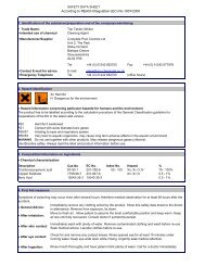
Part # Qty. Description1 1 Jet Housing2 2 Adaptor - Male, PVC 2-1/2” X 90/110 mm2a 2 Coupling, PVC 110 mm x 4”3 1 Adaptor - Male, PVC 1/2”4 2 90° Hose Fitting - Air Regulator, Plastic 1/4”5 1 Fitting - Hose, Air Regulator, Plastic 1/4”6 1 Y-Fitting - Air Regulator7 1 Hose - Air Regulator 8 X 3mm (1.4meters)8 6 Clamp - Hose, Air Regulator 14/9 SS9 1 Holder - Air Regulator10 2 Bolt - Air Holder, Slot/pan M6 X 30 mm SS11 2 Nut - Air Holder, M6 SS12 2 Washer - Air Holder, M6 SS13 1 Gasket - Air Holder 60 X 11 X 2 mm16 1 Adaptor - Female, PVC 1/2”17 1 Adaptor - Male, PVC 1/2”18 1 Ring - Hose 313/7Part # Qty. Description19 2 Washer SS20 1 Plug - Rubber 7mm21 1 <strong>To</strong>p Part - Air Regulator22 1 Bottom Part - Air Regulator23 1 Bolt W/hole - Air Regulator, Brass M10 X 8024 1 Ring - Hose, Air Regulator 16 X 30 X 18mm25 1 Gasket - Air Regulator 42 X 11 X 2mm26 1 Gasket with Knobs - Jet Housing27 1 Gasket - Clamping Ring28 1 Ring - Clamping29 12 Bolt - Clamping Ring, slot M8 X 30 SS30 1 Cover - Gunite31 4 Stud - Gunite Cover, All Thread, Zinc M8 X 8032 4 Washer - Gunite Cover, M833 4 Nut - Stud, Gunite Cover M8 SS38/1 1 Pneumatic Button (White)40 1 Nut - Pneumatic Button, Plastic43/1 1 Cover - Nozzle46 1 Clamp - Hose, Pneumatic Button 8.7 mm47 1 10 M Air Tube 4 X 1.5 mm (Per Meter)49 5 Tapping Screw - Nozzle Cover, Phil. 4.8 X 19 SS50 1 Volume Control Knob51 10 Bolt - Nozzle Housing, Slot M8 X 130 SS52 12 Bolt - Nozzle Housing, Phillips M8 X 30 SS53 1 Housing - Nozzle54 2 Nozzle - 40 mm55 2 I T Gasket - Tension Cup 103 X 81.5 X 0.6 mm56 2 Seat - Nozzle57 2 Spacer - Nozzle 6.2 mm58 2 Spacer - Nozzle 1 mm59 2 Tension Cup - Nozzle60 8 Washer - Lock, Tension Cup M6 SS61 8 Nut - Tension Cup M6 SS62 2 O-ring - Tension Cup 11.3 X 2.4mm63 1 Volume Control Disc64 1 Control Spindle67 1 Retainer - Shaft, Control Spindle68 8 Bolt - Tension Cup, Phillips M6 X 25 SS80/1 1 Control Box BJC-7-GFCI84 1 Cap - Nozzle, Close off89 1 Massage Hose 5 ft. With Pulsator89/1 1 Massage Hose 15 ft. With Pulsator (optional)93 1 Cover - Rectangular94 4 Washer - Rectangular Cover M8 SS95 4 Bolt - Rectangular Cover, Slot M8 X 20 mm95/1 4 Bolt - Rectangular Cover, Slot M8 X 80 mm96 4 Plug - Rectangular Cover97 1 Cover - Button98 2 Bolt - Jet Housing, Slot/Pan M8 X 30 mm SSExploded <strong>View</strong> for Super Sport121011171918/2016151439
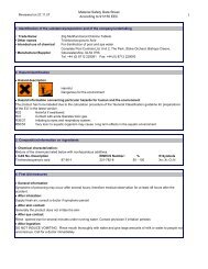
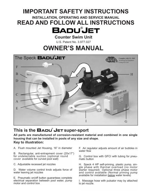
ClassicDifferences between thesuper-sport andClassicGeneral:<strong>The</strong> BADUJET CLASSIC is smaller in diameter(12” instead of 16”). It has only one jet and no regulatorknob to adjust the flow of water.1. Plumbing the BADUJET CLASSIC<strong>The</strong> center of the housing should be 11.5” (instead of10”) BELOW water level for maximum efficiency. <strong>The</strong>suction and discharge line may be 3” instead of the4” required for the large unit.Air RegulatorAir Hose4”Cover8”7.12”Protective jacketConnection frompump 3”12.4”o10”o9.30”o8.66”5.11”8.46”9.21”10.62”11.5”10”Jet Nozzle14.7”4.6”10.74”Connection topump 3”Rectangular anti-entrapment coverPneumatic ButtonFig. 2 & 32. Concrete or Gunite Installation<strong>The</strong> screws used to mount the ring cover are M6 instead of M8.Clamping ring<strong>Pool</strong> WallGasket1.7”0.5”oM8x40Air Line0.25”oWater Level10”o11.41” ~4”M6x60PressureSuction100.25”oFig. 4 & 5Unit housing
3. Liner and or Fiberglass <strong>Pool</strong> Installation<strong>The</strong> center of the housing should be 11.5” BELOWwater level for maximum efficiency. Place gasket withknobs (#26) BEHIND pool wall. Place clamping ringgasket (#27) in front of pool wall.<strong>The</strong> two holes at 18 0 from the vertical axis and thetwo holes (top & bottom) at the air regulator will allowboth housing and air regulator to be mounted withcounter-sunk bolts (M6) before the liner is placed.4. Installation of Housing<strong>The</strong> BADUJET has no control knob, therefore thepre-assembled nozzle housing with jet can be inserteddirectly into the jet housing. Next, the 6 bolts M6 x25 (#52) and the 5 bolts M6 x 100 (#51) are screwedinto the housing.All other instructions are the same for both theB ADUJ ET super-sport and the B ADUJ ETCLASSIC.PLEASE READ ALL BADUJET INSTRUCTIONSBEFORE INSTALLATION!10” o1.7”0.5” o0.25” o Water Level36 o18 o ”0.25” o9.25” oExploded <strong>View</strong> forBADUJET Classic141518/20 19 171698Part # Qty. Description1 1 Jet Housing2 2 Adaptor - Male, Housing PVC 2” X 75 mm /3”3 1 Adaptor - Male, Housing PVC 1/2”5 2 Nipple - Hose, Air Regulator, Plastic 1/4”7 1 Hose - Air Regulator 8 X 3 mm X 1.4 Meters8 2 Clamp - Hose, Air Regulator 14/9 SS9 1 Holder - Air Regulator10 2 Bolt - Air Holder, Slot/pan M6 x 30 SS11 2 Nut - Air Holder Bolt M6, SS12 2 Washer - Air Holder M613 1 Gasket - Air Holder 60 X 11 X 2 mm16 1 Adaptor - Female, PVC 1/2”17 1 Adaptor - Male, PVC 1/2”18 1 Ring - Hose 313/719 2 Washer SS20 1 Plug - Rubber 7 mm21 1 <strong>To</strong>p Part - Air Regulator22 1 Bottom Part - Air Regulator23 1 Bolt W/hole - Air Regulator, Brass M10 X 8024 1 Ring - Hose, Air Regulator 16 X 30 X 18 mm25 1 Gasket - air Regulator 42 X 11 X 2 mm11 1210Part # Qty. Description26 1 Gasket with Knobs - Jet Housing27 1 Gasket - Clamping Ring28 1 Ring - Clamping29 10 Bolt - Clamping Ring, Slot M6 X 25 SS30 1 Cover - Gunite31 4 Stud - Gunite Cover, All Thread, M6 X 8032 4 Washer - Stud, Gunite Cover, Zinc M633 4 Nut - Stud, Gunite Cover M6 SS38/1 1 Pneumatic Button40 1 Nut - Pneumatic Button, Plastic43/1 1 Cover - Nozzle46 1 Clamp - Hose, Pneumatic button 8.7 mm47 10m Air tube 4 X 1.5 mm (per meter)49 4 Tapping Screw - Nozzle Cover, Phil. 4.8 X 1651 5 Bolt - Nozzle Housing, Slot M6 X 97 mm SS52 6 Bolt - Nozzle Housing, Slot M6 X 25 mm SS53 1 Housing - Nozzle54/1 1 Nozzle - Adjustable Flow 40 mm55 1 it Gasket - Tension Cup 103 X 81.5 X 0.6 mm56 1 Seat - Nozzle57 1 Spacer - Nozzle 6.2 mm58 1 Spacer - Nozzle 1.5 mm59 1 Tension Cup - Nozzle60 4 Washer - Lock, Tension Cup M6 SS61 4 Nut - Tension Cup M6 SS62 1 O-ring - Tension Cup 11.3 X 2.4 mm68 4 Bolt - Tension Cup, Phillips M6 X 25 mm SS80/1 1 Control Box - BJC - 7 - GFCI89 1 Massage Hose - 5ft with Pulsator89/1 1 Massage Hose - 15ft with Pulsator93 1 Cover - Rectangular94 4 Washer - Rectangular Cover M6 SS95 4 Bolt - Rectangular Cover, Slot M6 x 16 mm95/1 4 Bolt - Rectangular Cover, Slot M6 X 60 mm96 4 Plug - Rectangular cover97 1 Cover - button98 2 Bolt - Jet Housing, Slot/pan M6 X 30 mm SS311
What size pool do I need? <strong>The</strong> BADUJET canbe installed in any size pool. However, we recommenda minimum length of 14' and a minimumwidth of a swimming lane.What size plumbing is necessary? How far awayfrom the BADUJET can the pump be installed?Use 4" plumbing up to 30'. For runs longer than 30'use 6" plumbing. <strong>The</strong> pump can be placed as closeto BaduJet as local codes will allow.How many amps does the pump operate at?Maximum 19.4 amps @ 230 VWhat size breaker do I need? You must use a 40amp breaker to avoid nuisance tripping.Does it matter if the housing is installed higher orlower than the manual states? Yes, the center ofthe housing (the two nozzles) should be 10" BELOWwater level for proper performance of unit.Frequently Asked QuestionsCan the air regulator be placed elsewhere? Yes,as long as it is not continuously flooded with water.What if water is discharging out of air regulatorwhen pump is running? <strong>The</strong> screws (Part # 51) thatmount the nozzle housing (Part # 53) are not fullytightened OR o-rings (Part # 62) on the tension cup(Part # 59) are missing or have rolled out of positionduring installation.Can the pump be placed below water level? Yes.However, for best performance we recommend orderingpump for flooded suction (Model 21-80/33 G) insteadof self-priming (Model 21-80/33 GS). We recommendinstalling valves for ease of maintenance.How far away can the air button function properly?A maximum of 50'. Consult factory for distances over 50’.Do I need to install a motor starter? No. <strong>The</strong> pumphas a built-in thermal overload.SAVE THESE INSTRUCTIONS!LIMITED WARRANTY<strong>The</strong> manufacturer supplies a limited warranty to the originalconsumer purchaser of the BADUJET on the followingterms and conditions:1. <strong>The</strong> BADUJET is warranted to be free from defects inmaterial and workmanship for a period of twelve (12)months from the date that the BADUJET is originallyinstalled.2. Notwithstanding any provision herein to the contrary,the warranties and obligations hereunder shall not in anyevent extend for more than 2 years beyond the date ofshipment of the BADUJET from Speck Pumps-<strong>Pool</strong><strong>Product</strong>s, Inc. in Jacksonville, Florida.3. Warranty is void in the following cases: damages whichresult in whole or in part from: (a) careless or improperinstallation of the BADUJET; (b) improper or negligentuse and maintenance of the BADUJET: (c) tamperingwith the BADUJET by unauthorized repair personnel; (d)ground movement; (e) substitution of parts and/or components.4. <strong>The</strong> manufacturer's sole obligation hereunder shall beto replace or repair any defective BADUJET. <strong>The</strong> manufacturerreserves the absolute right to determine whetherany defective BADUJET should be replaced or repaired.5. Any customer who wishes to make a claim under thisLimited Warranty shall notify Speck Pumps, of such claimby telephone or by mail. After the customer has beenauthorized to return a defective BADUJET, the customermust return the BADUJET to Speck Pumps.Any goods returned to Speck Pumps without prior authorizationwill be returned to the shipper unopened. SpeckPumps shall not bear any costs or risks incurred in shippinga defective BADUJET to Speck Pump or in shippinga repaired or replaced B ADUJ ET to a customer.6. Speck Pumps will charge customers for all non-warrantywork which it may perform. Warranty work will not beperformed until the customer has accepted the price quoted .7. Except as specifically set forth above, no other warranties,whether express or implied, including, withoutlimitation, the implied warranties of merchantabilityand fitness for a particular purpose, are made by themanufacturer. In no event will the manufacturer beliable for any loss, including time, money, goodwill,lost profits and consequential damages based on contract,tort or other legal theory, which may arise hereunderor from the use, operation or modification of thepump, motor or associated parts. <strong>The</strong> maximum liabilityof the manufacturer hereunder shall not exceed theamount actually paid by the customer for the pump,motor and associated parts.8. Some states do not permit limitations on the terms ofimplied warranties or on the recovery of incidental or consequentialdamages. Accordingly, the limitations containedin paragraph 7, may not apply to certain customers.9. This warranty gives customers specific legal rights.Customers may have other rights which may vary fromstate to state. <strong>The</strong> BADUJET is manufactured underlicense from Speck Pumpen, GERMANY.Date of Installation: _________________________________________________________________________Installed By: ______________________________________________________________________________For Service Call: ___________________________________________________________________________________________________________________________________________________________________RT.3.KF.BADUJET8125 Bayberry RoadJacksonville, Florida 32256 USAPhone (904) 739-2626 Fax (904) 737-5261e-mail: info.usa@speck-pumps.comwebsite: www.usa.speck-pumps.comPOOL PRODUCTS, INCORPORATED