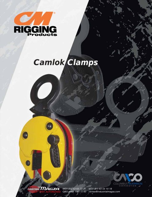
Camlok Clamps
Camlok Clamps
Camlok Clamps
- No tags were found...
You also want an ePaper? Increase the reach of your titles
YUMPU automatically turns print PDFs into web optimized ePapers that Google loves.
DIST. AUTORIZADOFor EFFICIENT, RELIABLE, and SECURE operation of a lifting clamp,the selection of the correct clamp for the job is of paramount importance:Vertical Plate <strong>Clamps</strong>, Type CZ92:The CZ92 range of clamps has been designed as a general purpose plate handling clamp for the steel fabrication industry.A clamp can lift steel plates from the horizontal to the vertical and over again through 180º. The necessary grip required tolift a plate is achieved by increasing the force applied to the clamp from the lifting sling by a system of links. The grippingforce is therefore proportional to the load lifted and self-actuating. The greater the load applied to the clamp, the greaterthe force. To initiate the self-actuating force a spring is incorporated into the clamp to give an initial bite on the material.®MEX (55) 53 63 23 31QRO (442) 1 95 72 60MTY (81) 83 54 10 18ventas@industrialmagza.comCLAMP SELECTION CRITERIADIST. AUTORIZADOMEX (55) 53 63 23 31QRO (442) 1 95 72 60MTY (81) 83 54 10 18ventas@industrialmagza.com®The clamps can be used on most types and grades of steel up to a surface hardness of 300 Brinell (32HRc). The clamp isalso suitable for certain grades of aluminum sheet and brass. The clamp is not suitable for steel over 300 Brinell (32HRc),stainless steel, lead, certain grades of copper and materials over 120ºC or 250ºF surface temperature.The working load limit of the clamp should be as close as possible to the actual load to be lifted. This ensures the clampis working at maximum effi ciency. When the effi ciency is reduced, the clamp suffers wear, thus will reduce the operationallife of the clamp. The maximum jaw capacity of the clamp should also be as close as possible to the plate thickness beinglifted. The spring will be stretched to its maximum and will be providing the maximum amount of initial grip to the lift.Excessive wear and a reduction in working life can be caused if a clamp is continuously used to lift the same thicknessmaterial. <strong>Clamps</strong> used for this type of application must have special inspection procedures applied. The one or two teeth ofthe moving jaw where the wear is concentrated must be inspected regularly. Where this type of application exists, rotationof the lifting clamps throughout the factory will increase the operational life of the clamp or specialist clamps can bemanufactured.Applications where the majority of lifting is thin light sheets will be best served by the selection of a narrow throat clamp.The pad side of a narrow throat clamp is moved closer to the moving jaw, thus increases the initial grip of the clamp bycausing the spring to be stretched.Applications where the plate is thick, but the load is small, are best suited to larger versions of a clamp. Moving the padside of the clamp away from the moving jaw creates a large version clamp. This has the advantage that the clamp has ajaw and mechanism best suited to the load applied and therefore is working at maximum effi ciency.Applications where the load is of hardened steel are not suitable for a clamp with teeth. A solution to this application mustbe formed from a range of non marking clamps.3
MINIMUM LOAD CRITERIADIST. AUTORIZADO®MEX (55) 53 63 23 31QRO (442) 1 95 72 60MTY (81) 83 54 10 18ventas@industrialmagza.comThe maximum load imposed on a device determines the structure and size of a plate clamp. The manufacturer will designthe internal components of the clamp to cope with these forces in consideration to the expected mechanical losses of thesystem.DIST. AUTORIZADOMEX (55) 53 63 23 31QRO (442) 1 95 72 60MTY (81) 83 54 10 18ventas@industrialmagza.com®Most <strong>Camlok</strong> clamps use sharp teeth to bite into the plate being lifted. Once a clamp has bitten into the plate, it effectivelybecomes one with the plate and therefore the plate can be safely lifted. The design of the clamp is such that the loadapplied to the hook ring is magnifi ed through a system of links to give a high gripping force to push the jaw teeth into thelifted plate. This gripping force is directly proportional to the load applied and self actuating (i.e. the higher the load applied,the higher the gripping force). This is known as the primary action. A secondary force generated by movement in the liftedplate supplements the primary gripping force, if the plate starts to slip from the clamp, the moving jaw is turned with theplate and the cam shape of the jaw increases the gripping force.Plate lifting clamps are simple machines. Like all machines with mechanisms they are subjected to naturally occurringphenomenon that reduce effi ciency. The phenomenons include;A Friction between moving parts. This will reduce the forces transmitted through the mechanism.B Inertia of the components. This will assert a degree of drag into the system slowing the reaction to changinginputs.The system of links and pivots in a plate clamp are simple, lightweight, and move over a small distance when in operation.The bearings in a plate clamp are generally simple “metal on metal” type, have large forces acting through them, and havepoor lubrication. Therefore, the friction loss can be signifi cant if the clamp is poorly maintained and suffering wear.The mechanism of the plate clamp is not static during operation but the movements are small. The inertia and friction ofthe mechanism can have a signifi cant effect on the performance of the clamp when lifting material from the horizontal tothe vertical position. The imposed load on the clamp fl uctuates from 50% of the load being lifted to zero and then to 100%at the “top dead center” position. (The point when the center of gravity of the plate passes over the pivot point contact onthe fl oor and is then lifted clear.)The amount a tooth penetrates into the lifted plate is dependent on a number of factors:A The gripping forceB The hardness of the plate being lifted.C The shaped of the clamp tooth4In simple terms, a tooth will penetrate into the material until the gripping force divided by the projected area of the toothcontact equals the indent stress of the material.
DIST. AUTORIZADO®MEX (55) 53 63 23 31QRO (442) 1 95 72 60MTY (81) 83 54 10 18ventas@industrialmagza.comCAMLOK LIFTING PAD DESIGNDIST. AUTORIZADOMEX (55) 53 63 23 31QRO (442) 1 95 72 60MTY (81) 83 54 10 18ventas@industrialmagza.comUnlike round pads on the market, <strong>Camlok</strong> uses a wide spacing or square pad layout. The wide spacing and layout of theteeth on the <strong>Camlok</strong> square pad help prevent the plate and clamp pivoting during lifting. This protects the straight teeth onthe moving jaw. All the teeth on the square pad can be considered to lift the load therefore maximizing effi ciency. The padsare marked with the maximum material hardness.Round PadsOn round pads the gripping force must push all the teeth into the material. However only the top and bottom quarter of thepad can be considered to effectively lift the load, thus reducing the effi ciency of the pad. There is no resistance to pivotingand straight teeth on the jaw suffer rotational stress and wear.®Resistance topivotingLOADSQUARE Vs ROUNDSQUAREROUNDPivoting Resistance Excellent PoorLOADNO LOADTeeth wear Excellent AverageFull surface contact Excellent PoorLoad Distribution Excellent PoorPad Bolt Stress Low HighLOADNo resistanceto pivoting<strong>Camlok</strong> JawThe prevention of load twisting by the wide pad and teeth layout on the <strong>Camlok</strong> clamp eliminates any twisting or pivotingload on the jaws. This helps prevent any unnecessary wear or damage on the teeth.The force of the load on the <strong>Camlok</strong> Clamp is distributed through the pad directly to the clamp housing. This means thereis no load stress on the pad bolts and reduces the possibility of pad bolt failure during lifting.When the load on round pads twists, the narrow jaw resists it.This places very high loads on the edge of the jaw. The jaw is notdesigned to sustain this pivoting load.5
DIST. AUTORIZADO®MEX (55) 53 63 23 31QRO (442) 1 95 72 60MTY (81) 83 54 10 18ventas@industrialmagza.comCZ SERIES Vertical Plate <strong>Clamps</strong>Things to Remember• Weight of plate to lift• Hardness of plate to lift• Type of material to lift• Position of plate to lift• Can plate be marked, is a non marking clamp required?DIST. AUTORIZADOMEX (55) 53 63 23 31QRO (442) 1 95 72 60MTY (81) 83 54 10 18ventas@industrialmagza.com®DON’Ts• DO NOT side load clamp more than 15º - use type CY or CX clamp for side loading• DO NOT lift plates with a temperature of 120ºC/ or 250ºF• DO NOT use to lift stainless steel, lead, and copper. For stainless steel plate, useLJ or HG Clamp.• DO NOT use on a double, triple, or quad sling. When using two clamps to lift a steelplate, a lifting beam must be used between the two clamps, so the clamps operatein a vertical position. Use a CY or CX clamp for slings with more than one leg.AGCEBHCZ SPECIFICATIONSDFModelWorking Load LimitMinMaxJawCapacityDimensionsA B C D E F G HWeightlb. lb.in. in. in. in. in. in. in. in. in. lb.CZ920.5 120 1,100 0 to 5/8 3.898 7.677 1.142 1.299 1.850 1.969 1.890 0.433 3.3CZ921.5 350 3,300 0 to 3/4 4.961 8.858 1.969 1.929 2.756 3.228 2.165 0.472 6.6CZ922 450 4,400 0 to 1-1/4 7.559 12.283 3.150 2.953 3.780 3.937 3.189 0.787 17.6CZ923 675 6,600 0 to 1-1/4 7.559 12.283 3.150 2.953 3.780 3.937 3.189 1.181 22.0CZ924 1,100 8,800 0 to 1-1/4 7.756 14.606 3.150 2.677 3.661 5.079 0.787 1.181 26.5CZ924/L* 1,100 8,800 1-1/8 to 2-3/8 8.976 15.354 3.150 2.677 3.661 5.079 0.787 1.181 39.7CZ926 1,600 13,200 0 to 2 11.535 19.055 3.504 3.740 5.630 5.079 0.984 1.378 46.3CZ928 2,150 17,600 0 to 2 11.535 19.370 3.504 3.740 5.630 5.079 0.984 1.654 57.3CZ928/L* 2,150 17,600 2 to 4 14.252 20.630 3.504 4.488 5.630 5.079 0.984 1.654 70.5CZ9210 3,350 22,000 0 to 2 11.535 21.457 4.331 3.740 5.630 5.472 0.984 1.772 66.1CZ9210/L 3,350 22,000 2 to 4 14.252 21.457 4.331 4.488 5.630 5.472 0.984 1.772 81.6CZ9215* 6,650 33,000 0 to 2 14.173 24.134 5.118 4.921 6.378 8.031 1.772 2.165 165.3CZ9215/L* 6,650 33,000 2 to 4 18.110 26.693 5.118 6.890 6.378 8.031 1.772 2.165 194.0CZ9220* 8,850 44,000 0 to 2-1/2 18.189 29.724 5.118 6.496 8.268 9.252 1.772 2.559 271.2CZ9220/L* 8,850 44,000 2-1/2 to 5 22.047 31.693 5.118 7.677 8.268 9.252 1.772 2.559 299.8CZ9230* 13,250 66,000 0 to 2-1/2 18.189 28.819 2.362 6.496 8.268 11.614 2.559 - 429.9* Products available upon request7
CY & CX SERIES Hinged Plate <strong>Clamps</strong>DIST. AUTORIZADO®MEX (55) 53 63 23 31QRO (442) 1 95 72 60MTY (81) 83 54 10 18ventas@industrialmagza.comDIST. AUTORIZADOMEX (55) 53 63 23 31QRO (442) 1 95 72 60MTY (81) 83 54 10 18ventas@industrialmagza.comThe CY series of plate clamps can be used on all structural steel plates up to surface hardness of 300 Brinell. These clamps are designedto be used with two leg chain sling for lifting longer plates. With the swiveling hook ring, the CY series of clamps can be fitted to asteel plate in any position. These clamps can turn a plate from the horizontal to vertical lift over the edge. Sufficient clamping of the loadis achieved by this special shape of the hook ring.The CX series clamps are a more robust heavy duty model of the CY clamp. The CX clamp has a reinforced plate at the top of themouth, and a heavy duty hook ring. The CX clamp is more suitable for turning vertically racked plates.®Used on all hot rolled structural steel plates and sections up to a surface hardness of 300Brinell (32HRc)Available in capacities of 1 ton up to 10 tonsJaw capacities available up to maximum of 4”Lifts plates from horizontal to vertical position and vice versa through 180º<strong>Clamps</strong> can be used with 2 leg slingsClamp has serrated teeth and will mark plateSelect a clamp with a working load limit as close as possible to the actual load being liftedand the maximum jaw capacity should be as close as possible to the plate thicknessRepair centers available to service your productsReplacement parts available for clampsCY SERIESDON’Ts• DO NOT lift loads less than 20% of Working Load Limit of clamp• DO NOT lift plates with a temperature of 120ºC/ or 250ºF• DO NOT use to lift stainless steel, lead, and copper. For stainless steel plate, use LJ or HGClamp.8CX SERIES
DIST. AUTORIZADO®MEX (55) 53 63 23 31QRO (442) 1 95 72 60MTY (81) 83 54 10 18ventas@industrialmagza.comCY & CX SERIES Hinged Plate <strong>Clamps</strong>C®CIFHEDDIST. AUTORIZADOMEX (55) 53 63 23 31QRO (442) 1 95 72 60MTY (81) 83 54 10 18ventas@industrialmagza.comBBEGDAGFAHICYCXCY SPECIFICATIONSModelWorking Load LimitMinMaxJaw CapacityDimensionsA B C D E F G H IWeightlb. lb. in. in. in. in. in. in. in. in. in. in. lb.CY1 450 2,200 0 to 3/4 4.961 10.630 1.969 1.929 2.756 3.740 2.480 0.472 0.906 10.1CY2 900 4,400 0 to 1-1/4 7.559 15.039 3.150 2.953 3.780 5.197 3.622 0.787 1.181 26.5CY3 1,350 6,600 0 to 1-1/4 7.559 15.039 3.150 2.953 3.780 5.197 3.622 0.787 1.181 30.9CX SPECIFICATIONSModelWorking Load LimitMinMaxJawCapacityDimensionsA B C D E F G H IWeightlb. lb. in. in. in. in. in. in. in. in. in. in. lb.CX3 1,000 6,600 0 to 1-1/4 7.756 20.276 2.638 5.433 0.748 2.677 3.661 3.189 4.331 26.5CX6 2,650 13,200 0 to 2 11.496 29.016 3.740 6.929 1.102 3.740 5.630 5.394 7.402 83.8CX6/L* 2,650 13,200 2 to 4 14.449 30.906 3.858 7.087 1.102 4.528 5.630 5.315 7.402 105.8CX8* 3,550 17,600 0 to 2 11.496 29.016 3.858 6.929 1.102 3.740 5.630 5.354 8.268 86.0CX8/L* 3,550 17,600 2 to 4 14.449 30.906 3.858 7.087 1.102 4.528 5.630 5.354 8.268 112.4CX10* 4,400 22,000 0 to 2 14.173 35.551 4.331 7.677 1.299 4.921 6.378 6.693 8.780 134.5CX10/L* 4,400 22,000 2 to 4 17.559 36.260 4.409 7.677 1.299 6.614 6.378 6.693 8.780 167.51209030LOADAngleModel CodeCY1 CY2 CY3CX SERIESImperialdegrees lb. lb. lb.0-30 4,400 8,800 13,20030-90 2,200 4,400 6,60090-120 1,100 2,200 3,300CY SERIES9
CH SERIES Horizontal Plate <strong>Clamps</strong>DIST. AUTORIZADO®MEX (55) 53 63 23 31QRO (442) 1 95 72 60MTY (81) 83 54 10 18ventas@industrialmagza.comThe CH clamps are sold in pairs and can be used on all types of materials in plate form, providing the plate can withstand the forcesDIST. AUTORIZADOMEX (55) 53 63 23 31QRO (442) 1 95 72 60MTY (81) 83 54 10 18ventas@industrialmagza.comimposed. Standard CH clamps are supplied with smooth jaws. The clamps are suitable for lifting one plate at a time, or bundles of platesprovided the plates are the same width, have straight square sides, and are thicker than 10% of the maximum jaw capacity of the clamp.CH clamps should never be side loaded. The smooth jaws can be replaced with serrated hardened steel teeth and used on material upto 300 Brinell (32HRc).®CH clamps must be used in pairsAvailable in pair capacities of 1 ton up to 10 tonsJaw capacities available up to maximum of 6”CH clamps have smooth teeth and can be used on all types of materialA single pair of CH clamps can be used with a 2 leg slingCH clamps can be furnished with serrated teethWhen serrated teeth are used, maximum hardness of material to liftshould not exceed 300 BrinellIntegral shackle on the CH clamp designed to accept relevant size chainsling hookCH clamps can be designed to suit any load or plate thicknessRepair centers available to service your productsReplacement parts available for clampsSPECIFICATIONSDON’Ts• DO NOT use CH clamps with for side loadingModelWorking LoadLimit(per pair)Jaw CapacityDimensionsA B C D E F GWeight(per pair)12lb. in. in. in. in. in. in. in. in. lb.CH1 2,200 1/4 to 1-1/4 1.181 3.228 2.362 3.937 1.260 1.732 0.512 13.2CH2 4,400 1/4 to 1-1/4 1.181 3.228 2.362 3.937 1.969 2.874 0.709 24.3CH2/L 4,400 3/4 to 2 1.181 3.228 2.362 3.937 1.969 2.874 0.709 26.5CH4 8,800 1/4 to 1-1/4 1.575 4.409 3.150 3.937 2.520 3.622 0.984 37.5CH4/L 8,800 2 to 4 1.575 4.409 3.150 3.937 2.520 3.622 0.984 50.7CH6 13,200 1/4 to 3 2.165 6.772 3.937 5.118 3.543 5.118 1.378 101.4CH6/L 13,200 2 to 5 2.165 6.772 3.937 5.118 3.543 5.118 1.378 123.5CH8 17,600 1/4 to 3 2.165 6.772 4.134 5.118 3.543 5.118 1.378 116.8CH8/L 17,600 2 to 5 2.165 6.772 4.134 5.118 3.543 5.118 1.378 132.3CH10 22,000 1/4 to 4 2.559 8.465 4.724 5.906 4.488 5.118 1.378 209.4CH10/L 22,000 2 to 6 2.559 8.465 4.724 5.906 4.488 5.118 1.378 238.1HH8* 17,600 1/4 to 2 2.165 6.614 4.134 5.118 4.134 5.118 3.543 46.3HH8/L 17,600 2 to 4 2.165 6.614 4.134 5.118 3.543 4.488 1.378 61.7* Products available upon request
DIST. AUTORIZADO®MEX (55) 53 63 23 31QRO (442) 1 95 72 60MTY (81) 83 54 10 18ventas@industrialmagza.comTHK SERIES Horizontal Plate <strong>Clamps</strong>The THK Series Clamp has a jaw that pivots in the reverse direction to our normal horizontal clamps and is designed to lift andhandle thin sheet plate that tends to sag when being lifted. The reverse jaw feature ensures that the grip of the clamp increases the morethe plate deflects under its own self weight. <strong>Clamps</strong> are used in pairs with a two legged chain sling. Two pairs of clamps supported froma lifting beam must be used when handling long plates. Single plates only can be lifted.DIST. AUTORIZADOMEX (55) 53 63 23 31QRO (442) 1 95 72 60MTY (81) 83 54 10 18ventas@industrialmagza.com®THK clamps must be used in pairsAvailable in pair capacities of 3/4 ton up to 9 tonsJaw capacities available up to maximum of 2-1/4””Clamp has serrated teeth and will mark plateA single pair of THK clamps can be used with a 2 leg slingCH clamps can be furnished with serrated teethMaximum hardness of material to lift should not exceed 300Brinell (32HRc)Repair centers available to service your productsReplacement parts available for clamps30º 30ºCBDON’Ts• DO NOT use THK clamps with 3 or 4 leg slings, use a spreader beamEADFSPECIFICATIONSModelWorking Load Limit(per pair)MinMaxPlateDimensionsA B C D E FWeight(per pair)lb. lb. in. in. in. in. in. in. in. lb.THKO.75 90 1,600 0 to 1 4.625 5.375 0.750 1.000 2.875 3.125 6.6THK1.5 200 3,300 0 to 1-3/8 5.375 6.625 1.000 1.250 3.125 3.500 13.2THK4.5* 500 9,900 0 to 1-3/4 8.625 8.625 1.750 4.000 4.375 4.375 35.3THK6.0* 700 13,200 0 to 2-3/8 8.375 10.500 1.375 1.875 4.875 4.375 50.7THK9 1,000 19,800 0 to 2-3/8 8.750 11.375 1.625 2.250 4.500 5.500 77.2* Products available upon request13
CP SERIES Pile Pinching <strong>Clamps</strong>DIST. AUTORIZADO®MEX (55) 53 63 23 31QRO (442) 1 95 72 60MTY (81) 83 54 10 18ventas@industrialmagza.comThe CP clamps are designed specifically for pitching sheet steel and have the advantage of an attached rope for easy release from theground. The rope presents a quicker method than the laborious procedure of release using a standard shackle. Piles must be preparedwith a pitching hole of correct dimensions. These clamps are not designed to extract a driven pile and must not be used to remove pilesunder any circumstances. For pile removal use the PP series clamps.DIST. AUTORIZADOMEX (55) 53 63 23 31QRO (442) 1 95 72 60MTY (81) 83 54 10 18ventas@industrialmagza.com®Designed specifi cally for pitching sheet steel pilingIdeal clamp for heavy constructionRope is fi tted for easy release from the groundAvailable up to 5 ton capacityRepair centers available to service your productsReplacement parts available for clampsFCEADBSPECIFICATIONSModelWorking LoadLimitDimensionsA B C D E FWeightlb. in. in. in. in. in. in. lb.CP2 4,400 8.976 0.787 2.000 0.787 16.750 8.500 41.9CP3 6,600 8.976 1.024 2.500 1.181 17.875 8.875 50.7CP5 11,000 8.976 1.378 3.250 1.181 19.875 9.500 72.814
DIST. AUTORIZADO®MEX (55) 53 63 23 31QRO (442) 1 95 72 60MTY (81) 83 54 10 18ventas@industrialmagza.comHGC SERIES Hand Grip <strong>Clamps</strong>The <strong>Camlok</strong> hand grip clamp is designed to carry or pull any object that will fit into the jaws. It can be used on all structural steelDIST. AUTORIZADOMEX (55) 53 63 23 31QRO (442) 1 95 72 60MTY (81) 83 54 10 18ventas@industrialmagza.complates and sections up to a surface hardness of 300 Brinell. This clamp is not suitable for steel over 300 Brinell (32HRc), stainless steel,lead, copper and materials over 120ºC/ 250ºF surface temperature. The hand clamp is used to manually lift and carry material in a workshopenvironment. The innovative design enables the operator to open and attach the clamp to sheet material by depressing the liftinghandle. Two pre-tensioned hardened serrated toothed jaws grip the sheet securely when the handle is released.®Designed for manual liftsMaximum working load limit 500 lbs.Pre-tensioned serrated teeth for secure gripSuitable for material thickness up to 3/8”Excellent clamp for workshop usePrevents plate slippageMaximum hardness of material to lift should notexceed 300 Brinell (32HRc)Repair centers available to service your productsReplacement parts available for clampsBGCHDON’Ts• DO NOT lift plates with a temperature of 120ºC/ or 250ºF• DO NOT use to lift stainless steel, lead, and copperDASPECIFICATIONSF = ThicknessModelWorking LoadLimitPlateDimensionsA B C D E F G HWeightlb. in. in. in. in. in. in. in. in. in. lb.HGC 500 0 to 3/8 4.25 7.25 3.875 1.875 2.125 0.875 0.375 5.125 2.015
THS SERIES Horizontal Plate <strong>Clamps</strong>DIST. AUTORIZADO®MEX (55) 53 63 23 31QRO (442) 1 95 72 60MTY (81) 83 54 10 18ventas@industrialmagza.comThe <strong>Camlok</strong> THS series of horizontal plate clamps can be used single or with two leg slings with a maximum angle of 60º. TheDIST. AUTORIZADOMEX (55) 53 63 23 31QRO (442) 1 95 72 60MTY (81) 83 54 10 18ventas@industrialmagza.comclamps are designed to be used on structural steel plates up to a surface hardness of 300 Brinell (32HRc) providing the plate can withstandthe forces imposed. The clamps have a spring/lever operated mechanism which securely locks the clamp onto the horizontallypositioned plate. The ability to lock the clamp onto the plate enables a single operator to quickly set up the plate for lifting. The designallows you to lift and handle single sheet steel plates in a horizontal position. They are particularly useful for loading plates into guillotines,presses, punching machines and folding press. Caution should be used so that maximum single angle is not exceeded.®Available in capacities up to 3 tonsHandles plates up to 1-1/2” thickSpring lever for locking into placeCan be used in single or 2 leg slingsMaximum hardness of material to lift should not exceed 300Brinell (32HRc)Use lifting beams for longer platesRepair centers available to service your productsReplacement parts available for clampsHGACDON’Ts• DO NOT use with endless or 3 or 4 leg slings• DO NOT exceed 60º angle when lifting• DO NOT lift plates with a temperature of 120ºC/ or 250ºFB• DO NOT use to lift stainless steel, lead, and copperFEDSPECIFICATIONSModelMinMaxDimensionsWorking Load Limit Jaw Capacityin. in.A B C D E F G HWeight16lb. in. in. in. in. in. in. in. lb.THS0.75 90 1,600 0 to 3/4 10.039 3.819 1.969 0.591 2.756 3.150 0.472 0.591 6.6THS1.5 175 3,300 0 to 1-3/8 13.189 4.724 2.756 0.787 3.150 3.543 0.591 0.669 13.2THS3 500 9,900 0 to 1-3/4 17.717 7.717 3.543 2.323 4.331 4.331 0.787 1.181 37.5
DIST. AUTORIZADO®MEX (55) 53 63 23 31QRO (442) 1 95 72 60MTY (81) 83 54 10 18ventas@industrialmagza.comTSH SERIES Screw <strong>Clamps</strong>DIST. AUTORIZADOMEX (55) 53 63 23 31QRO (442) 1 95 72 60MTY (81) 83 54 10 18ventas@industrialmagza.comThe TSH clamps are designed for pulling and holding sheet metal, girders, and related steel objects. The clamps are supplied completewith an alloy shackle that allows for pulling 180º. Screw cam pulling clamps are primarily used as anchor points to allow fabricationsto be pulled together and positioned during assembly or prior to welding. These clamps have a screw cam pad. When load is appliedto the clamp, the circular toothed pad pivots in a cam action, gripping the load. The clamps are attached by turning the screwed threadedaxle.®Available in capacities up to 5 tonsJaw capacity up to 3” thickOutstanding means of holding and securing loadsHigh force screw threadsHardened steel jawsSwivel jaws increase grip if plate movesMaximum hardness of material to lift should not exceed 300 Brinell (32HRc)NOT recommended for lifting applicationsCOMMON LEVER TOOL PROBLEMGCHBEDON’TsSPECIFICATIONSADF• DO NOT lift plates with a temperature of 120ºC/ or 250ºF• DO NOT use with stainless steel, lead, and copper• DO NOT over torque the threaded axle, this could cause damage to the padModelWorking LoadLimitJaw CapacityDimensionsA B C D E F G HWeightlb. in. in. in. in. in. in. in. in. in. lb.TSH1.5 3,300 0 to 1-1/4 5.118 10.039 2.559 4.528 2.953 5.000 1.024 3.701 15.4TSH3 6,600 0 to 2 6.693 11.417 2.913 4.921 3.346 5.669 1.181 4.646 24.3TSH5 11,000 0 to 3-1/8 10.039 18.504 5.118 6.890 5.315 9.449 1.969 6.890 59.517
HG SERIES Vertical Plate <strong>Clamps</strong>DIST. AUTORIZADO®MEX (55) 53 63 23 31QRO (442) 1 95 72 60MTY (81) 83 54 10 18ventas@industrialmagza.comThe <strong>Camlok</strong> High Grip clamps are designed to give additional grip forces to products during lifting. The High Grip has an additionalDIST. AUTORIZADOMEX (55) 53 63 23 31QRO (442) 1 95 72 60MTY (81) 83 54 10 18ventas@industrialmagza.comlever in the clamping mechanism thus asserting a higher gripping force on the plate being lifted. The clamp has been designed to liftplates with harder surfaces as well as for use with stainless steel plates. The HG series is suitable for hardness up to 371 Brinell (40 HRc).<strong>Clamps</strong> can be used for lifting and turning plates from the horizontal to vertical position or vice versa. The standard clamp is fitted with ahook ring but can be alternatively supplied with a short length of chain. <strong>Clamps</strong> will mark the surface of the material being lifted.®Can be used on hot rolled structural steel plates and sections up to a surface hardnessof 376 Brinell. If over 376 Brinell (40 HRc) use LJ clamp.Can be used to lift Stainless Steel Plates or plates with harden surfaces due to coldrollingLift plates from horizontal to vertical position and vice versa through 180ºClamp has serrated teeth and will mark plateAvailable in capacities up to 4 tonsJaw capacities up to ¾”Smaller jaw range means more effi cient for thinner steelRepair centers available to service your productsReplacement parts available for clampsGABFDON’Ts• DO NOT side load clamp more than 15º• DO NOT lift plates with a temperature of 120ºC/ 250ºF or Higher• DO NOT use clamps on a double chain sling, when using two clamps to lift a steel plate,a lifting beam must be used between the two clamps to allow clamps to hang verticalESPECIFICATIONSCModelWorking Load LimitMinMaxJaw CapacityDimensionsA B C E F GWeight18lb. lb. in. in. in. in. in. in. in. lb.HG0.5 100 1,100 0 to 3/8 1.654 9.055 5.827 2.165 3.110 1.969 11.0HG1 150 2,000 0 to 5//8 3.661 11.698 8.268 2.638 4.488 2.638 26.5HG2 450 4,400 0 to 3/4 4.331 16.378 12.008 4.016 6.260 3.150 48.5HG3* 700 6,600 0 to 3/4 4.331 16.378 12.008 4.016 6.260 3.150 59.5HG4* 900 8,800 0 to 3/4 4.724 13.189 12.008 4.016 6.220 3.150 70.5* Products available upon request
DIST. AUTORIZADO®MEX (55) 53 63 23 31QRO (442) 1 95 72 60MTY (81) 83 54 10 18ventas@industrialmagza.comCG SERIES Girder Turning <strong>Clamps</strong>The CG clamps are general purpose clamps and can be used on rolled steel joists, beams, and fabrications up to a surface hardness ofDIST. AUTORIZADOMEX (55) 53 63 23 31QRO (442) 1 95 72 60MTY (81) 83 54 10 18ventas@industrialmagza.com300 Brinell (32HRc). This clamp can lift and turn girders through 90º and is designed to meet the requirements of the heavy steel industry.The clamp is designed to land the beam in either vertical or horizontal position. It incorporates a positive lock onto one of the uppermostedges, which will allow the beam to be set down with the flange vertical. For long girders, fabrications, and welded structures, two clampsand a lifting beam may be required.®Available in capacities up to 4 tonsJaw capacities up to 2”Can be used on beams, fabrications, channels, rolled steeljoistsThis clamp can lift and turn beams up to 90ºCan land beam in vertical or horizontal positionClamp is fi tted with a cam/spring operated safety lockUse 2 clamps when lifting long lengths of beamThese clamps can turn girders up to 90ºRepair centers available to service your productsReplacement parts available for clampsBDCHIFDON’Ts• DO NOT lift plates with a temperature of 120ºC/ 250ºF or HigherSPECIFICATIONSGAEModelWorking Load LimitMinMaxJawCapacityDimensionsA B C D E F G H IWeightlb. lb. in. in. in. in. in. in. in. in. in. in. lb.CG1 250 2,200 0 to 5/8 8.307 3.543 1.969 0.512 1.693 10.354 2.520 13.780 13.268 13.2CG2 450 4,400 0 to 1-1/4 11.417 5.512 3.150 0.787 2.362 12.480 3.937 18.307 17.126 30.9CG4 900 8,800 0 to 1-1/4 11.417 6.339 3.504 0.787 3.031 12.835 4.252 20.591 18.976 41.9CG6 1,350 13,200 7/16 to 2 13.268 6.732 3.504 0.984 4.055 14.764 5.709 21.693 20.630 81.619
TTG SERIES Horizontal Girder <strong>Clamps</strong>DIST. AUTORIZADO®MEX (55) 53 63 23 31QRO (442) 1 95 72 60MTY (81) 83 54 10 18ventas@industrialmagza.comThe TTG clamps are designed to lift and transport structural steel beams in the vertical position. The flanges are transported inthe horizontal position. The clamps are fitted with a <strong>Camlok</strong> spring operated safety lock and is operated by pulling the locking handleupwards. Long beams should be lifted with two clamps attached on opposite beam flanges.DIST. AUTORIZADOMEX (55) 53 63 23 31QRO (442) 1 95 72 60MTY (81) 83 54 10 18ventas@industrialmagza.com®Available in capacities up to 7.5 tonsAvailable to fi t fl anges up to 1-3/4”Used to transport girders with fl anges in the horizontal positionMaximum hardness of material to lift should not exceed 300 Brinell(32HRc)For short beams, a single clamp can be usedLonger beams should be lifted using 2 clamps and a lift beam with clampslocated on opposite sidesRepair centers available to service your productsReplacement parts available for clampsCBDON’Ts• DO NOT lift plates with a temperature of 120ºC/ 250ºF or HigherDASPECIFICATIONSEFModelWorking Load LimitMinMaxPlateDimensionsA B C D E FWeight20lb. lb. in. in. in. in. in. in. in. lb.TTG1.5 200 3,300 0 to 1-1/8 9.000 10.875 3.750 1.750 2.750 4.000 12.1TTG3 350 6,600 0 to 1-3/8 11.125 11.625 3.125 2.125 2.875 4.500 24.3TTG4.5* 1,000 9,900 0 to 1-1/2 12.375 13.250 3.500 2.375 3.000 4.625 32.0TTG7.5* 1,650 16,500 0 to 1-3/4 14.500 15.000 4.375 2.500 3.625 6.625 61.7* Products available upon request
DIST. AUTORIZADO®MEX (55) 53 63 23 31QRO (442) 1 95 72 60MTY (81) 83 54 10 18ventas@industrialmagza.comBTG SERIES GroundworksThe BTG clamps are designed to lift and handle concrete manhole pipes in the vertical position. These clamps enable the manholetrench size to be minimized and facilitate accurate positioning of pipes on top of each other. These clamps are sold in sets of three.Attachment and removal of the clamps from the pipes is extremely easy due to the simple and straight forward design.DIST. AUTORIZADOMEX (55) 53 63 23 31QRO (442) 1 95 72 60MTY (81) 83 54 10 18ventas@industrialmagza.com®Available in capacities up to 3-3/4 tonsAvailable jaw width up to 8-1/2”Solid construction designSold in sets of 3 (Chain Sling not included)Simple handlingLarge jaw capacityLight weight designService friendlyMade in ChinaSPECIFICATIONSNote: Chain Sling not includedModelWorkingLoad Limit(Per set of 3)Jaw Capacity(Z)DimensionsA B C DE(Mouth)F(Pressure Line)Weightlb. in. in. in. in. in. in. in. lb.BTG1500/3 3,300 1-1/2 to 4-3/4 5.315 5.315 0.709 7.087 6.496 3.937 75.0BTG3000/3 6,600 2 to 7 6.890 3.937 1.024 12.205 9.646 6.890 132.3BTG3000L/3 6,600 3-1/2 to 8-5/8 6.890 3.937 1.024 12.205 9.646 6.890 172.021
DIST. AUTORIZADOSCREWLOK BEAM CLAMP WITH SHACKLE®MEX (55) 53 63 23 31QRO (442) 1 95 72 60MTY (81) 83 54 10 18ventas@industrialmagza.com<strong>Camlok</strong> Beam clamps are designed for attachment to the lower flanges of structural steel beams to provide a semi permanent liftingpoint. The clamps can be quickly and easily attached via the screw type mechanism. This series of clamps is fitted with a suspensionshackle allowing for quick and easy component attachment.DIST. AUTORIZADOMEX (55) 53 63 23 31QRO (442) 1 95 72 60MTY (81) 83 54 10 18ventas@industrialmagza.com®Available in capacities up to 10 tonsAvailable jaw width up to 12”Shackle furnished for quick and easycomponent attachmentAvailable in single or double clampsSPECIFICATIONSModelWorkingLoad LimitFlangeDimensionsA B C D E FWeightADFlb. in. in. in. in. in. in. in. lb.SC921 2,200 3 to 8-1/4 12.625 12.125 1.750 8.250 5.375 2.625 11.0SC922 4,400 3 to 8-1/4 12.625 12.875 1.750 8.250 5.375 2.875 13.5SC923 6,600 4 to 10-5/8 16.125 14.750 1.750 10.625 6.500 4.000 17.5SC923/ 6,600 3 to 12 17.375 16.500 1.750 12.000 8.625 4.000 20.0SC925 11,000 4 to 10-5/8 16.125 15.375 2.125 10.625 8.500 4.375 22.0SC925/ 11,000 3 to 12 17.125 17.125 2.125 12.000 8.625 4.375 26.5SC9210 22,000 3 to 12 18.125 20.000 3.250 12.000 8.625 4.375 35.5EBCSC SERIES TWIN BEAM CLAMPModelWorking LoadLimitMinimumFlange WidthMaximumWeightlb. in. in. lb.SC922T 4,400 2.995 8.387 28.7SC923T 6,600 3.994 10.783 35.3SC923/LT 6,600 2.995 12.181 44.1SC925/T 11,000 3.994 10.783 50.7SC925/LT* 11,000 2.995 12.181 59.522
DIST. AUTORIZADO®MEX (55) 53 63 23 31QRO (442) 1 95 72 60MTY (81) 83 54 10 18ventas@industrialmagza.comCTP SERIES Beam ClampDIST. AUTORIZADOMEX (55) 53 63 23 31QRO (442) 1 95 72 60MTY (81) 83 54 10 18ventas@industrialmagza.comCTP Screwlok clamps are based on the SC beam clamp series, where we have incorporated a four wheel trolley. The easy installationto any beam makes the CTP suitable for affixing and moving hoists, pulleys, and loads. The trolley is adjustable to suit various beamflange widths by turning the handle of the screw mechanism. Tightening the locking lever nut against the trolley side plate aligns thetrolley wheels at the correct span. The trolley wheels have pre-lubricated ball bearings. The model CTP1 is of lightweight constructionand fitted with polyurethane plastic wheels.®Available in capacities up to 3 tonsAvailable to fi t fl anges up to 8-1/4”Adjustable to fi t various fl ange widthsPre lubricated ball bearings on each unitEasily attaches hoist, pulleys or slingsRepair centers available to service your productsReplacement parts available for clampsMade in ChinaGHFEDJBKACSPECIFICATIONSModelWorkingLoad LimitJawCapacityMin CurveRadiusABMin Max Min MaxCDimensionsD E F GH J KWeightlb. in. in. in. in. in. in. in. in. in. in. in. in. in. in. lb.CTP1 2,200 2-3//8 to 5-7/8 0.035 3.740 7.283 3.228 4.291 1.024 2.598 2.874 6.299 6.024 4.134 2.953 0.866 4.9CTP2 4,400 3 to 7-7/8 0.045 4.921 9.843 4.173 6.102 1.654 3.543 3.937 10.236 8.071 5.472 5.118 0.787 21.8CTP3 8,800 3 to 7-7/8 0.055 5.315 10.236 5.039 6.732 1.969 4.331 4.921 12.205 8.661 6.102 5.906 0.866 38.623
CLB SERIES Lifting LugsDIST. AUTORIZADO®MEX (55) 53 63 23 31QRO (442) 1 95 72 60MTY (81) 83 54 10 18ventas@industrialmagza.comThe CLB container lugs are supplied in sets of four. They are available with a total capacity of 56 tons. The CLB series serve asflexible lashing points for the transportation of containers. The CLB lugs are mounted horizontally to the side of the container at eitherthe top or bottom fixing holes. This model has a spring loaded bolt to prevent accidental release.DIST. AUTORIZADOMEX (55) 53 63 23 31QRO (442) 1 95 72 60MTY (81) 83 54 10 18ventas@industrialmagza.com®Spring loaded bolt to prevent accidental releaseMounted at the side of the container in either upper or lower holesEasy installation and removal, simple insert and turn installationDesigned to eliminate the dangerous use of standard hooksLugs cannot drop out when slings become slackLugs can be used left hand or right hand turnsFor maximum capacity use a lifting beam in conjunction with theCLB lifting lugsSPECIFICATIONSGModelWorking LoadLimit(Per set of 4)DimensionsA B C D E F GWeightBCDE20Imperiallb. in. in. in. in. in. in. in. lb.CLB32 70,500 5.984 7.126 1.772 1.457 2.874 2.953 1.575 39.7CLB40 88,100 5.984 7.126 1.772 1.457 2.874 2.953 1.575 39.7AF50TVertical40T36º32T50ºREDUCTION OFWORKING LOAD LIMITAngle of lift must be specifi edwhen ordering CLB lifting lugsCLB DESIGNDesigned to eliminate the use ofstandard hooks as attachments.24
DIST. AUTORIZADO®MEX (55) 53 63 23 31QRO (442) 1 95 72 60MTY (81) 83 54 10 18ventas@industrialmagza.comCLB SAFETY INFORMATIONNOTE: Minimum angle will depend on W.L.L. RequiredDIST. AUTORIZADOMEX (55) 53 63 23 31QRO (442) 1 95 72 60MTY (81) 83 54 10 18ventas@industrialmagza.com®1. Spreader beam addsstability to lift.2. CLB lugs can be usedin the top fi tting also.3. Un-symmetrically loadedcontainers can be handledby using lifting beams andshortening chain slings.1. Bottom side 2. Top side 3. Bottom endFor maximum load capacity a lifting frame can be used with the lugs attached as above.DO NOT USELifting frames offer little stability.X X XNOT recommended, sling maydamage container.FOR FURTHER INFORMATION CONTACTCUSTOMER SERVICE AT 800-888-098525
CAMLOK SPARE PARTSDIST. AUTORIZADO®MEX (55) 53 63 23 31QRO (442) 1 95 72 60MTY (81) 83 54 10 18ventas@industrialmagza.com‘92 SERIES - VERTICAL PLATE LIFTING CLAMPSNo special tools are required to repair clamps. Heat may berequired to release the bonding compound on some screws.After repair use STUDLOCK on all screws removed.Always quote clamp serial number, part description and modelwhen ordering spares.ReferenceDescription10 Shell plates (set of 4)16 Shell pins (set of 3)17 Shell screws (6 off)20 Internal assembly27 Spring31 Hook ring32 Hook ring pin40 Cam assembly41 Cam47 Locking lever and pin50 Pad assemblyONLY USE GENUINE CAMLOK SPARE PARTS4050413247 10163110DIST. AUTORIZADOMEX (55) 53 63 23 31QRO (442) 1 95 72 60MTY (81) 83 54 10 18ventas@industrialmagza.com201727®CZ - VERTICAL PLATE LIFTING CLAMPSNo special tools are required to repair clamps. Heat may berequired to release the bonding compound on some screws.After repair use STUDLOCK on all screws removed.31Always quote clamp serial number, part description and modelwhen ordering spares.ReferenceDescription10 Shell welded assembly20 Internal assembly27 Spring31 Hook ring50322732 Hook ring pin40 Cam assembly and lever41 Cam47 Locking lever and pin404150 Pad assembly60 Jaw bolt assembly10 20ONLY USE GENUINE CAMLOK SPARE PARTS476026
DIST. AUTORIZADO®MEX (55) 53 63 23 31QRO (442) 1 95 72 60MTY (81) 83 54 10 18ventas@industrialmagza.comCAMLOK SPARE PARTSCY - “HINGED” VERTICAL PLATE CLAMPSNo special tools are required to repair clamps. Heat may berequired to release the bonding compound on some screws.After repair use STUDLOCK on all screws removed.Always quote clamp serial number, part description and modelwhen ordering spares.ReferenceDescription10 Shell plates (set of 4)16 Shell pins (2 each)17 Shell screws (set of 4)20 Internal assembly27 Spring32 Hook ring pin34 Hook ring fork35 Swivel hook ring37 Eye bolt and nut40 Cam assembly41 Cam47 Locking lever and pin50 Pad Assembly60 Jaw bolt assemblyONLY USE GENUINE CAMLOK SPARE PARTS40504137164732346035DIST. AUTORIZADOMEX (55) 53 63 23 31QRO (442) 1 95 72 60MTY (81) 83 54 10 18ventas@industrialmagza.com17102027®CX - “HINGED” VERTICAL PLATE CLAMPSNo special tools are required to repair clamps. Heat may berequired to release the bonding compound on some screws.35After repair use STUDLOCK on all screws removed.Always quote clamp serial number, part description and modelwhen ordering spares.3734ReferenceDescription10 Shell welded assembly20 Internal assembly27 Spring32 Hook ring pin34 Hook ring fork50321035 Eye cam37 Eye bolt and nut2740 Cam assembly41 Cam404147 Locking lever and pin50 Pad assembly60 Jaw bolt assemblyONLY USE GENUINE CAMLOK SPARE PARTS4760 2027
DIST. AUTORIZADO®MEX (55) 53 63 23 31QRO (442) 1 95 72 60MTY (81) 83 54 10 18ventas@industrialmagza.comDIST. AUTORIZADOMEX (55) 53 63 23 31QRO (442) 1 95 72 60MTY (81) 83 54 10 18ventas@industrialmagza.com®www.cmworks.comCAMLOKA COLUMBUS McKINNON BRANDAmherst, NYPhone: 800-888-0985 or 716-689-5400Fax: 716-689-5644CMR-CAMLOK-1009SS 2.5M 10/09 MU© 2009 Columbus McKinnon Corporation


