X-Rack Eight Channel Input Module Owner's ... - Solid State Logic
X-Rack Eight Channel Input Module Owner's ... - Solid State Logic
X-Rack Eight Channel Input Module Owner's ... - Solid State Logic

Create successful ePaper yourself
Turn your PDF publications into a flip-book with our unique Google optimized e-Paper software.
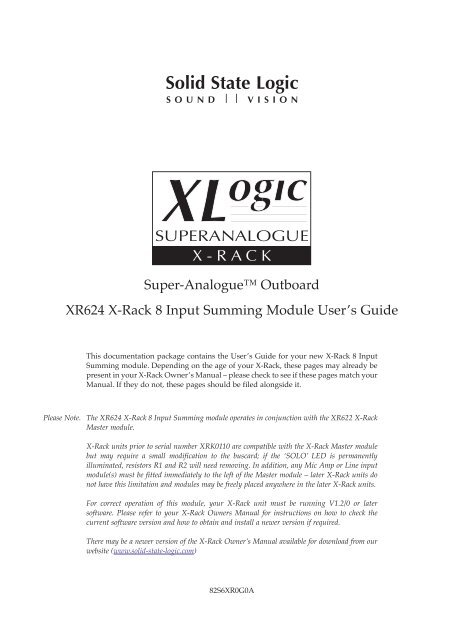
X-<strong>Rack</strong> 8 <strong>Input</strong> Summing <strong>Module</strong>G. Summing <strong>Module</strong>G.1 IntroductionThe <strong>Eight</strong> <strong>Input</strong> Summing module was developed in response to requests from X-<strong>Rack</strong> users for a lineinput module designed to accommodate larger quantities of stereo line level inputs from studio sourcessuch as multichannel audio interfaces, sub mixers and synthesizers. The module is designed for use withthe X-<strong>Rack</strong> XR622 Master module and is equipped with eight line level inputs configured as four stereopairs, each pair featuring on/off and mono/stereo switching, routing onto the internal Mix bus. Inaddition to this, there are stereo inserts available on the first two input pairs. The X-<strong>Rack</strong> Master moduleprovides the monitoring facilities that would be expected; mix amps, monitor outputs and a headphonefeed – please refer to the X-<strong>Rack</strong> Master module documentation for a full description.G.2 ConnectionINSERTSEND/RTN1 – 4LINE IN1 – 8The rear panel of the module carries a pair of 25-way ‘D’ connectors. The left-handconnector provides Insert Sends and Insert Returns for the first two pairs of <strong>Input</strong>swhilst the right-hand connector provides access to the eight balanced inputs (fourstereo pairs).This module contains no variable gain controls and operates at unity gain.XR624G.3 OperationThis module is a fixed gain summing amplifier and so there are naturally few frontpanel controls.G.3.1 <strong>Input</strong> 1/2 and <strong>Input</strong> 3/4 1Signals applied to these inputs will be permanently available on the Insert Sends;the Insert Return for either pair can be selected in place of the Line <strong>Input</strong> by pressingthe appropriate ‘INS’ switch. Note that the Insert Return can also be used to providean alternative input to these input amplifiers.Normally the left hand input of any pair will feed the left mix bus; the right inputwill feed the right mix bus. The ‘MONO’ switch will over-ride this behaviour bysumming both left and right inputs and feeding both mix busses together at unitygain.The ‘ON’ switch will act to un-route the appropriate pair of inputs from the X-<strong>Rack</strong>mix bus.G.3.2 <strong>Input</strong> 5/6 and <strong>Input</strong> 7/8 2These two pairs of inputs operate in a similar manner to the first two pairs of inputsabove, but lack the Insert Send/Return.SELINPUT 1/2INPUT 3/4INPUT 5/6INPUT 7/8INSMONOON1INSMONOONMONOON2MONOONPage G-1
X-<strong>Rack</strong> Owner’s ManualG.4 Performance SpecificationThe following page contains audio performance specification figures for the X-<strong>Rack</strong> Summing module. Noother <strong>Solid</strong> <strong>State</strong> <strong>Logic</strong> products are covered by this document and the performance of other <strong>Solid</strong> <strong>State</strong><strong>Logic</strong> products can not be inferred from the data contained herein.G.4.1 Measurement ConditionsFor each set of figures on the following pages, the specific unit and test setup will be stated at thebeginning of that section. Any changes to the specified setup for any particular figure(s) will be detailedbeside the figures to which that difference applies.G.4.2 Measurement ReferencesUnless otherwise specified the references used in this specification are as follows:• Reference frequency: 1kHz• Reference level: 0dBu, where 0dBu ≈ 0.775V into any load• Source impedance of Test Set: 50Ω• <strong>Input</strong> impedance of Test Set: 100kΩ• All unweighted measurements are specified as 22Hz to 22kHz band limited RMS and are expressed inunits of dBu• All distortion measurements are specified with a 36dB/Octave low pass filter at 80kHz and areexpressed as a percentage• The onset of clipping (for headroom measurements) should be taken as 1% THD• Unless otherwise quoted all figures have a tolerance of ±0.5dB or 5%• All measurements are made with the operating level switch set for +4dBuG.4.3 PerformanceSignal applied to one channel of an X-<strong>Rack</strong> Summing module and routed to Mix Bus. Signal measured onMix Output. All other inputs un-routed from the bus under test. Mix Bus Gain control set to 0dB.GainTHD + Noise(+24dBu applied, 0dB gain)Frequency ResponseNoise(<strong>Input</strong> terminated with 150Ω)Fixed, 0dB< 0.005% from 20Hz to 10kHz,< 0.008% at 20kHz±0.1dB from 20Hz to 20kHz–3dB at 150kHz< –80dBuPage G-2
X-<strong>Rack</strong> 8 <strong>Input</strong> Summing <strong>Module</strong>G.5 Connector DetailsInsert Send/Rtn 1 –4Line In 1 –8Location:Rear PanelLocation:Rear PanelConn’ Type:25-pin ‘D’ Type FemalePin Description Cct1 Insert Return 4 (–ve)14 Insert Return 4 (+ve)2 0V15 Insert Return 3 (–ve)3 Insert Return 3 (+ve)16 0V4 Insert Return 2 (–ve)17 Insert Return 2 (+ve)5 0V18 Insert Return 1 (–ve)6 Insert Return 1 (+ve)19 0V7 Insert Send 4 (–ve)20 Insert Send 4 (+ve)8 0V21 Insert Send 3 (–ve)9 Insert Send 3 (+ve)22 0V10 Insert Send 2 (–ve)23 Insert Send 2 (+ve)11 0V24 Insert Send 1 (–ve)12 Insert Send 1 (+ve)25 0V13 n/c87654321Conn’ Type:25-pin ‘D’ Type FemalePin Description Cct1 Line <strong>Input</strong> 8 (–ve)14 Line <strong>Input</strong> 8 (+ve)2 0V15 Line <strong>Input</strong> 7 (–ve)3 Line <strong>Input</strong> 7 (+ve)16 0V4 Line <strong>Input</strong> 6 (–ve)17 Line <strong>Input</strong> 6 (+ve)5 0V18 Line <strong>Input</strong> 5 (–ve)6 Line <strong>Input</strong> 5 (+ve)19 0V7 Line <strong>Input</strong> 4 (–ve)20 Line <strong>Input</strong> 4 (+ve)8 0V21 Line <strong>Input</strong> 3 (–ve)9 Line <strong>Input</strong> 3 (+ve)22 0V10 Line <strong>Input</strong> 2 (–ve)23 Line <strong>Input</strong> 2 (+ve)11 0V24 Line <strong>Input</strong> 1 (–ve)12 Line <strong>Input</strong> 1 (+ve)25 0V13 n/c87654321Note that the ‘D’ type connector binding posts fitted to the X-<strong>Rack</strong> 8 <strong>Input</strong> Summing <strong>Module</strong> are 4-40 UNC thread.Page G-3
X-<strong>Rack</strong> Owner’s ManualG.6 Physical SpecificationDepth: 200mm / 7.9 inches including front panel knobs, excluding connectors275mm / 10.9 inches including front panel knobs and connectorsHeight:171mm / 6.75 inchesWidth: 35mm / 1.4 inches front/rear panels49mm / 1.9 inchesoverall width (front and rear panels are offset)Weight:260g / 9.5 ouncesBoxed size: 190mm x 290mm x 70mm / 7.5" x 11.5" x 2.5"Boxed weight: 460g / 16.5 ounces* All values are approximateG.7 Environmental SpecificationAs per X-<strong>Rack</strong> – see page 19.Page G-4