Using ASME format
Using ASME format
Using ASME format
- No tags were found...

Create successful ePaper yourself
Turn your PDF publications into a flip-book with our unique Google optimized e-Paper software.
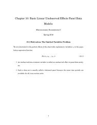
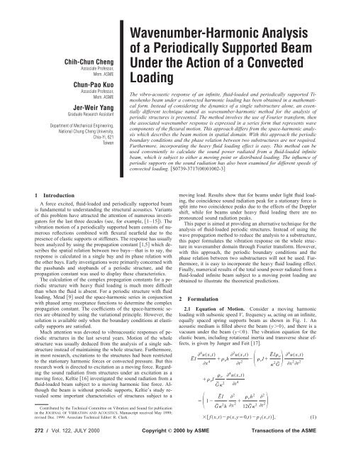
P˜ 1,tk sn unl,te jnl . (9)Introduce a new transformed term by the notation asunl,t 12Ũ,te jnl d. (10)Substituting Eq. 10 into Eq. 9 yields the spring force:Fig. 1Schematic representation of problem geometryP˜ 1,t k s2Ũ,t ne jnl d.(11a)where u(x,t) represents the transverse displacement of the beam,I the cross-sectional moment of inertia per unit width, thedensity of the beam, 2 the cross-sectional shape factor, h theheight of the beam, f (x,t) the external moving force, p(x,y0,t) the acoustic pressure acting on the beam surface andp 1 (x,t) the force from the spring supports. Ē and Ḡ are the complexelastic and shear modulus, respectively:ĒE1 j, (2)ḠĒ21 ,where is the structural damping and is the Poisson ratio. Themoving point force f (x,t) is given byf x,t f o e jt xVt, (3)where f o is the strength of external force per unit width. The forcep 1 (x,t) from the periodic spring supports is given byp 1 x,tn k s ux,txnl, (4)where k s is the stiffness of the spring support per unit width and lis the spacing between two adjacent supports. The pressurep(x,y0,t) acting on the beam surface satisfies the Helmholtzequation: 2x 2 2y 2 1 C o2 2 2px,y,t0, (5)twhere C o is the speed of the sound in the acoustic medium. Theboundary condition at y0 is given by 2 u ot 2 p, (6)yyowhere o is the density of the acoustic medium. After applying thespatial Fourier trans<strong>format</strong>ion to the external moving force, Eq.3 becomesF˜ ,t f o e jVt . (7)For a steady-state response, Eq. 7 implies that the transformeddisplacement Ũ(,t), sound pressure P˜ (,y,t) and periodicspring force P˜ 1(,t) will have the common factor e j(V)t in awavenumber domain 16, and can be rewritten asŨ,tUe jVt ,P˜ ,y,tP,ye jVt ,(8a)(8b)P˜ 1,tP 1 e jVt .(8c)By applying the spatial Fourier trans<strong>format</strong>ion to Eq. 4, itbecomesApplying the Poisson summation formula 18 to Eq. 11a, thelatter becomesP˜ 1,t k s2Ũ,t2n l2nd.(11b)Substituting Eq. 8a into Eq. 11b, the periodic spring force canbe expressed byP˜ 1,t k slnU 2nl e j2n/lVt . (11c)2.2 The Wavenumber Harmonic Series. From Eq. 11c,it shows that the reaction forces from elastic supports containnumerous wavenumber components. This implies that the beamwavenumber response should have the common wavenumbercomponents. Hence, the prior assumption of the transformed displacementŨ(,t) will not complete again due to the presence ofnumerous wavenumber components, except for a stationary excitation.A new wavenumber-harmonic series that represents thetransverse response should be developed for this purpose. Thisseries is written in the form:Ũ,tn u n e j2n/lVt , (12)where n is an integer. It is called a ‘‘wavenumber-harmonic series’’to distinguish it from a space-harmonic series 6. However,with this approach, the periodic boundary conditions and thephase relation between two substructures will not be used. SubstitutingEq. 12 into Eq. 11c, the spring force becomesP˜ 1,t k sln urnr 2rl e j2n/lVt (13)The spatial Fourier trans<strong>format</strong>ion is also applied to Eqs. 5 and6 Appendix A, then the sound pressure is rewritten aswhereP˜ ,y,tn S n e jK ny y e j2n/lVt , (14)S n j o 2n 2l VK nyu n ,Journal of Vibration and Acoustics JULY 2000, Vol. 122 Õ 273
B¯n1 16 2 C ok o h• 2 2C L k o hH n ,C¯ k s /El/h ,D¯n D nE/h j k o hC oC L16 2 1 j2 o H n (23c)(23d)H n 2 , (23e)H n k o h2nhM12l . (23f)The relationship between dimensionless parameter k o h and wavenumberratio is2 12 2C ok o h k ok BE1/2 . (23g)Equations 21 and 22 can be expressed in a set of infinite equationsas follows:Rearranged Eq. 24 as(24)(25)Equation 25 represents a set of linear algebraic equations in theunknown expansion coefficients ū n (). From Eq. 25, ū n () termcan be obtained by using a Gaussian elimination algorithm althoughthe coefficient matrix is complex. Substituting ū n () backinto Eq. 12 gives the explicit wavenumber response of the fluidloaded,infinite periodically supported beam asŪ,t ū n e j2n/k o hl/hM1t . (26)n2.4 The Total Radiated Sound Power. The total radiatedsound power is the sum of the sound power radiated by eachwavenumber component. By integrating the surface acoustic in-Journal of Vibration and Acoustics JULY 2000, Vol. 122 Õ 275
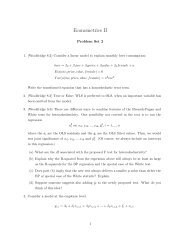
tensity over the entire beam, the radiated sound power per unitwidth, is given by Appendix Bwhereor o4 2n 1 2nl Mk o 2nl 2nl 1 1M 2nl Mk ofor1M 2nl Mk o 1 1M 2nl Mk ofor1M3 V Mk o 2nl Mk o 2nl2 2 u n 2 d,1M 2 Mk o.1M 2nl Mk o1M2 Mk o.1M 2nl(27)The dimensionless radiated sound power W per unit width is givenbyW• 4hE2 o f o 2 C o3where 2Hn 1k o h 3 n 3/2 •ū n 21•ReH n 2d,(28) 1 fork o h2nhM1lk o h1M2nhM1l1Mk o h2nhM1lk o h1M2nhM1l1M 2 ,or2n2nk o h l khM1o hhM1l 1 1M1M2 ,2n2nk o hhM1l k o hhM1lfor.1M1MEquation 28 will be evaluated numerically to examine influencesof the convected loading speed on the radiated sound power.,3 Analysis ParametersNumerical examples will now be presented to illustrate somefeatures of the theoretical results. Properties of the specific beammodel analyzed are as follows: E210 10 Nt/m 2 , 7800 kg/m 3 , h2.5410 2 m, 0.3, 2 0.85 and 0.01. The beam is assumed to be submerged in water (C o1500 m/s, o 1000 kg/m 3 ) with the elastic support spacingl/h100, and the stiffness ratio S0.01. The moving force isassumed to be a point force. In order to demonstrate effects of theconvected loading speed on radiated sound power, three differentMach numbers, M0.01, 0.3, and 0.8 were chosen. Numericalsolution of the infinite set of equations required the set to betruncated and will be discussed in the following section.4 Numerical Results and DiscussionFor a moving point force with Mach numbers range from 0.01to 0.8, the wavenumber responses of an unsupported beam withinthe wavenumber range from 50 to 50 is plotted in Fig. 2. Notclearly seen in Fig. 2, because of the perspective-viewing angleused in the three-dimensional plotting routine, are the nulls, indicatedby number , due to acoustic damping. The large spectralresponses of the fluid-loaded flexural wavenumber are indicatedby numbers and . Eventually as the convected loading speedincreases, the radiation damping at the acoustic wavenumber andthe flexural wavenumber are seen to vary nonlinearly. The peak inpositive wavenumber, indicated by number in this figure, representsthe flexural wave that propagates in the same direction asthe convected loading. With the increase of convected loadingspeed, this peak will move toward to great value of wavenumber.This phenomenon is due to Doppler effect. On the other hand, thepeak on the negative wavenumber, indicated by number , representsthe flexural wave of which the propagating direction isopposite to that of the convected loading. The wavenumber of thispeak decreases with increased convected loading speed. Hence,this wave component will travel faster than the positive-goingwave. This implies that the negative-going wave may be supersonic,and so will be responsible for the sound radiation.At certain convected loading speed, i.e., approximately at M0.4 in this figure, the flexural nearfields, indicated by numbers and emerge and become propagating. Note that there shouldbe two flexural nearfields and they become propagating at thesame wavenumber. When the flexural nearfields become propagating,one of them moves toward negative greater values ofwavenumber indicated by number , the other indicated by number moves close to one of the flexural waves and merges withit eventually. It is possible that this flexural nearfield may alsocontribute to the sound radiation.Fig. 2 Wavenumber response versus frequency and Machnumber for a water-loaded unsupported beam at k o hÄ0.05276 Õ Vol. 122, JULY 2000 Transactions of the <strong>ASME</strong>
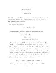
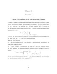
Fig. 3 Magnitude response for a water-loaded unsupportedbeam at k o hÄ0.05, MÄ0.01, 0.3 and 0.8Figure 3 is simply a slice through the wavenumber responsegiven in Fig. 2 within the wavenumber range from 100 to100 and at three different convected loading speeds, M0.01,0.3, and 0.8, respectively. For M0.01, the wavenumber responsepeaks are approximately symmetric at the wavenumber origin.Both of the peaks are identified as the propagating flexural waves.With the increased convected loading speed, the spectral responseof the unsupported beam changes in a predictable manner as describedpreviously. Clearly seen in this figure, there are four peaksin the wavenumber response for M0.3. Two of the peaks arereadily identified as the traveling flexural waves, one that is locatedapproximately at 30 is the positive-going flexural wave,the other is the negative-going flexural wave at 3. There arealso two flexural nearfields that emerge and become propagatingdue to the convected loading. One is located approximately at 20, the other almost merges with the negative-going flexuralwave at 4. For the case of M0.8, one of the propagatingflexural nearfield merges with one of the traveling flexural waves.The other flexural wave and flexural nearfield are out of the wavenumberrange, and so are not shown in this figure.Numerical solution of the infinite set of equations is required tobe truncated in Eq. 26. Unfortunately, no formula can give thenumber of terms required. The number of terms required dependson the support spacing, support stiffness, frequency of excitationand the speed of convected loading. In order to know how manyequations are of great importance in particular cases, the wavenumberdecomposition was performed. This was done by calculatingthe magnitude of each wavenumber component, ū n (),which was obtained by using Eq. 25. Shown in Fig. 4 are magnitudesof several components of the wavenumber response for awater-loaded beam with the spring support stiffness ratio S0.01, support spacing l/h100, Mach number M0.3 and excitedat the frequency k o h0.05. In this figure, it clearly demonstratesseveral facts. First, the largest peak was identified as thecomponent of wavenumber response corresponding to n0,which means no phase delay relative to the excitation. Second, asn increases or decreases, the magnitudes of ū n () get smaller.From the general trend indicated by these results, it is of considerableinterest to show that the magnitude of the largest peak ofū 50 () at 65 is much smaller than that of ū o () at 0.Hence, the wavenumber response series converges rapidly.Again, Fig. 5 illustrates magnitudes of several components ofthe wavenumber response for the same periodically supportedbeam described in Fig. 4 but subjected to a convected point loadingat speed M0.8. Comparing Fig. 5 with Fig. 4, contributionsFig. 5 Magnitude response for a water-loaded, periodicallyspring-supported beam, lÕhÄ100, SÄ0.01 at k o hÄ0.05, MÄ0.8Fig. 4 Magnitude response for a water-loaded, periodicallyspring-supported beam, lÕhÄ100, SÄ0.01 at k o hÄ0.05, MÄ0.3Fig. 6 Radiated sound power from a water-loaded, periodicallyspring-supported beam, lÕhÄ100, SÄ0.01 at k o hÄ0.05,MÄ0.01, 0.3 and 0.8Journal of Vibration and Acoustics JULY 2000, Vol. 122 Õ 277
from wavenumber components n2 to the total wavenumberresponse get progressively smaller with the increased convectedloading speed. Hence, only a few terms are required for Eq. 26to reach the convergent criteria. Note that no wavenumber components,except for n0, will exist for an unsupported beam. Thisimplies that the system behaves more like an unsupported infinitebeam while increasing the convected loading speed. Figure 5clearly demonstrates that the influences of spring supports decreasewhen the convected loading speed increases.Figure 6 is the sound power radiated from the specific modelwith spring support spacing l/h100, stiffness ratio S0.01 andat three different convected loading speeds, M0.01, 0.3, and0.8, respectively. Sound power radiated from an unsupportedbeam for M0.8 is also plotted together with other sound powercurves for the purpose of comparison. In the case of M0.01, it isinteresting to find that the radiated sound power shows pronouncedpeaks at a certain wavenumber ratios. Nonetheless, thesepeaks all occur at low wavenumber ratios. For the cases of M0.3 and 0.8, it is also clear that there are fluctuations in radiatedsound power at low wavenumber ratios. From the general trend ofthese curves, it shows that the influences of spring supports on theradiated sound power decrease while the wavenumber ratio andthe convected loading speed increase. Comparisons of the resultswith those obtained from an unsupported beam show that thepeaks in the radiated sound power greatly exceed those from theunsupported beam. From Eq. 11c, we observe that the reactionforces from elastic supports introduce numerous wavenumbercomponents in the wavenumber displacement Ū(,t). Althoughthe convected speed of loading is assumed to be subsonic, it ispossible that some of the wavelengths of the transformed displacementŪ(,t) are greater than the acoustic wavelength. Thisimplies that these wave components are supersonic, and are responsiblefor sound radiation. Of interest are the wavenumberratios at which the sound radiation curves have maxima. However,the locations of these peaks that are considered to be relatedto the nature of the wave propagation and attenuation in a periodicallysupported structure remain elusive.5 ConclusionAn alternative solution for the sound radiation from a fluidloading,periodic structure has been developed. The solution isobtained by Fourier wavenumber transforms of the whole structureinstead of reducing the analysis to a substructure. Hence, theperiodic boundary conditions and the phase relation between twosubstructures will not be used in this approach. It is worth notingthat the sound power radiated from a fluid-loaded periodic structureis calculated most conveniently if the surface motion of thisstructure can be expressed in a form in wavenumber domain. It isshown that the frequency-dependent propagating wavenumbercomponents of the responses are dependent on the velocity of theconvected loading. This phenomenon is attributed to the Dopplereffect. It is also clear that the influences of spring supports on theradiated sound power decrease while the wavenumber ratio andthe convected loading speed increase. The radiated sound power isseen to exhibit peaks at certain wavenumber ratios. Unfortunately,no formula so far could precisely help determine the locations ofthese peaks.AcknowledgmentsThis work was partially supported by the National ScienceCouncil of Taiwan, Republic of China under Contract No. NSC87-2212-E-194-019.Appendix AA Note on the Pressure Wavenumber Spectrum: Applyingspatial Fourier trans<strong>format</strong>ion to Eqs. 5 and 6, Eqs. 5 and 6becomen 2 2y 2 1 2 22 P˜ ,y,t0.C ot(A1) 2 ũ,t P˜ ,y,t ot 2 . (A2)yyoThe sound pressure equation isP˜ ,y,tn P n ,ye j2n/lVt . (A3)Substituting A3 into Eq. A1, the latter becomes 2 2y 2 1 2 22 pC ot n ,ye j2n/lVt 0.Equation A4 can be rewritten as 2nl 2 2y 2 2 V(A4)C o2p n ,y0. (A5)However, the radiation condition specifies that the sound pressureproduced by the beam motion must propagate away from thebeam and/or decay with the distance from the beam. It is easilyfound that the sound pressure of Eq. A5 isP n ,yS n e jK ny y ,(A6)wherej K ny ¦ 2 2nlfor 2 2nl 2nlfor 2 Mk o2 2nl Mk o2 Mk o2 2 Mk o2,k o and M are the acoustic wave number and the Mach number,respectively. Substituting Eq. A6 into Eq. A2, wefindS n ():j o 2nl2 VS n uK n . (A7)nyHence, the sound pressure P˜ (,y,t) is expressed asAppendix BP˜ ,y,tn S n e jK ny y e j2n/lVt .(A8)A Note on the Radiated Acoustic Power: The time averagedsound intensity is given by Morse and Ingard 19 asTĪ 1 PVdt,T0(B1)or Ī 1 Re Pu˙ *, (B2)2where Ī is the time-averaged sound intensity, P is the sound pressureon the beam surface and u˙ * is the beam surface velocity. Inorder to find the total acoustic power , the surface acoustic intensitydistribution may be integrated over the infinite length ofthe beam as278 Õ Vol. 122, JULY 2000 Transactions of the <strong>ASME</strong>
1RePx,y0,tu˙ *x,tdx. (B3)2Upon substituting the sound pressure and the surface velocity ofthe beam, the sound power becomes 2nl2 Vn K ny o4 Re u n e j2n/lVtd.•m 2ml Vu m*e j2m/lVt (B4)Then, after some algebraic manipulation, Eq. B4 is written as o4 n 2n 2m l V 2ml VRe 2nmvt/l u nu m*e j d.k ny(B5)This integral turns out to be dependent of time. The radiatedsound power will be zero when averaged over one period exceptfor nm. Thus, the averaged radiated sound power can be expressedas o4 n 2n 3l V u n Re 1 2 K nyd.(B6)Note that the denominator in Eq. B6 is real only over a restrictedinterval of the integration range. The radiated sound power is thenrewritten as o 4 2n 1 2nl 2nl3 V Mk o2 2 u n 2 d.(B7)This limits within which K ny is real is given as 2nl Mk o 2nl Mk o 1 1M1M 2 2nl Mk o 2nl Mk ofor,1M1Mor 2nl Mk o 2nl Mk o 1 1M1M2 2nl Mk o 2nl Mk ofor.1M1MAfter some algebraic manipulation, the radiated sound power isgiven in nondimensional form W asW• 4hE2 o f 0 2 C o3 2Hn 1k o h 3 n 3/2 •ū n 21•ReH n 2d,(B8)whereorH n 2nk o hhM12l ,2nk o h 2nlkhM1o hhM1l 1 1M1M2 ,2n2nk o hhM1l k o hhM1lfor1M1M2n2nk o h l khM1o hhM1l 1 1M1M2 ,2n2nk o hhM1l k o hhM1lfor.1M1MNomenclatureC L Longitudinal wave speedC o Sound speed in the acoustic mediumĒ Complex elastic modulusf o External force strength per unit widthf (x,t) Moving forceF˜ (,t) Moving force in wavenumber domainḠ Complex shear modulush Height of the beamI Cross-sectional moment of inertia per unitwidthj 1 2 Cross-sectional shape factork B Free bending wave number Acoustic wave numberk ok s Stiffness of the spring support per unit widthl Spacing between two adjacent supportsM Mach numberp(x,y0,t) Acoustic pressure acting on the beam surfaceP˜ (,y,t) Acoustic pressure in wavenumber domainp 1 (x,t) Spring support forceP˜ 1(,t) Spring support force in wavenumber domainS Stiffness ratiou(x,t) Transverse displacement of the beamŨ(,t) Transverse displacement of the beam in wavenumberdomainV Moving force speedW Dimensionless radiated acoustic power per unitwidth Wave number ratioJournal of Vibration and Acoustics JULY 2000, Vol. 122 Õ 279