Stepped Circular Waveguide Dual-Mode Filters for ... - IEEE Xplore
Stepped Circular Waveguide Dual-Mode Filters for ... - IEEE Xplore
Stepped Circular Waveguide Dual-Mode Filters for ... - IEEE Xplore
- No tags were found...

You also want an ePaper? Increase the reach of your titles
YUMPU automatically turns print PDFs into web optimized ePapers that Google loves.
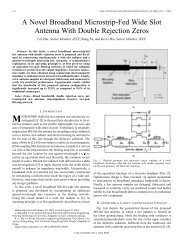
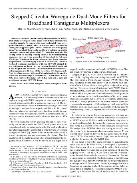
140 <strong>IEEE</strong> TRANSACTIONS ON MICROWAVE THEORY AND TECHNIQUES, VOL. 61, NO. 1, JANUARY 2013and thus will be neglected in the approximated mode chart calculations.It will be shown later that the maximum relative discrepancyin the calculated resonance frequencies by the approximatedtransmission line model with omitted and rigorousfull wave EM model is less than 6% in C band <strong>for</strong> the case of. Substituting the admittance expressions of eachmode in the two pieces of short-circuited transmission lines <strong>for</strong>and into (1), the resonances of the mode in an SCWDMcavity are then approximately governed by(2)Fig. 2. SCWDM cavity: (a) the physical structure, and (b) the equivalent circuitmodel (with neglected in calculation) <strong>for</strong> approximately generating themode chart.two lowest frequency channels are realized by SCWDM filters<strong>for</strong> their wider spurious-free bands. This design is experimentallyverified in the third design example: a triplexer (with oneSCWDM channel filter) that covers exactly the same 1 GHz frequencyrange as that in the 17-channel OMUX case. A C-banddesign example is also examined, further confirmed that a widespurious resonance clean frequency band can be created by appropriatelychoosing the diameters of an SCWDM cavity.II. THE MODE CHART OF AN SCWDM CAVITYAn SCWDM cavity is illustrated in Fig. 2(a), whereand are the lengths and radii <strong>for</strong> the small and largeradius sections, respectively. With appropriate combination ofand , the spurious resonances in a frequencyband can be moved away. This feature can be best viewed bythemodechartoftheSCWDMcavity,whichmaybeeffectivelyused <strong>for</strong> characterizing the resonance frequencies of variousmodes and choosing the optimum combination ofand .An approximate but efficient transmission line model isdeveloped <strong>for</strong> generating the mode chart of an SCWDM cavity.As shown in Fig. 2(b), an SCWDM cavity can be describedby an equivalent circuit of two short-circuited transmissionlines with different characteristic admittances. The parametersandare the characteristic admittance,propagating constant and the electrical length <strong>for</strong> the waveguidemode considered (e.g., in the small and large radiussections, respectively. The shunt susceptance accounts <strong>for</strong>the higher order mode effect of the step discontinuity, whichis frequency and mode dependant and thus is difficult to bemodeled by a closed-<strong>for</strong>m expression.When a chosen mode in an SCWDM cavity resonates, thetotal admittance of the mode at the step junction must equal tozero, that iswhere. Even though the characteristicadmittance ( and ) <strong>for</strong> a waveguide mode is not uniquelydefined, its frequency dependence is the same as that of its waveimpedance. Thus the transcendental equation (2) leads to a set ofunique resonance frequencies <strong>for</strong> each mode. For any givenand , the change of or will lead to the change of resonancefrequencies, collecting all these frequencies generates themode chart <strong>for</strong> the particular mode.The resonances of an SCWDM cavity can also be rigorouslyanalyzed by a full-wave EM simulation using an eigen solver.The full-wave generated mode chart has been used to crosscheckthe approximated results.In practice, the working mode in an SCWDM cavity resonatesnear the filter center frequency . There<strong>for</strong>e, when sweepingthe <strong>for</strong> making a mode chart, the electrical length of thecavity, i.e., , needs to be kept at <strong>for</strong> resonanceTo demonstrate, the mode chart of a C-band SCWDM cavitywith mm and mmisshowninFig.3,where the x-axis is the electrical length of mode in thesmaller radius section and the y-axis is the resonance frequenciesof the modes in the cavity. The solid lines are generatedby the approximated approach while the dashed lines are by afull-wave EM approach. In this example is fixed to<strong>for</strong> mode resonating near GHz. For equals0and , the frequencies represent the resonance frequencies <strong>for</strong>the uni<strong>for</strong>m cavities with radius of mm andmm, respectively. It can be seen from Fig. 3 that even thoughthere are some discrepancies between the two sets of curves,the mode chart generated by the approximated model is goodenough <strong>for</strong> a fast engineering design.The mode chart in a Ku-band SCWDM cavity, whosemm and mm, is also generated and is given inFig. 4. This SCWDM cavity is <strong>for</strong> realizing the channel filterof the lowest frequency channel of a wideband OMUX rangingfrom 10.6 GHz to 11.8 GHz. The of the filter is 10.73 GHz.By sweeping from 0 to , one can find that when is at thevicinity of , the spurious-free window is much expandedcomparing to a uni<strong>for</strong>m long CWDM cavity with radius ofeither or .A spurious-free range of an SCWDM cavity also depends onthe choices of radii and . Since the approximated approachis very fast, it would be straight<strong>for</strong>ward to generate aseries of mode charts with different and combinations.of the two waveg-is not significantUsually, the selected radius ratiouides is not smaller than 0.75, the effect of(1)III. DESIGN THEORY OF AN SCWDM FILTERDue to the different termination conditions, the two degeneratemodes, namely and modes (also known
142 <strong>IEEE</strong> TRANSACTIONS ON MICROWAVE THEORY AND TECHNIQUES, VOL. 61, NO. 1, JANUARY 2013B. Calculation of CouplingsAn input/output iris couples energy from the mode inthe rectangular waveguide to the mode in the circular waveguide.In calculating the I/O coupling of an SCWDM filter, theinput iris should also include the section of small radius cavityand the step discontinuity. The K impedance inverter [5]–[10] isused <strong>for</strong> determining the coupling (e.g., and <strong>for</strong>a 4-pole filter) and reflection phases and lookingat the I/O iris from the large radius cavity. The reflection phaseis an extra amount of phase introduced by an iris if comparedto a perfect electric conducting wall. It should be noted that theeffect of electrical length has been taken into account in thereflection phases. Equation (7) will be used to scale the inverterparameter to the corresponding coupling .The irises <strong>for</strong> inter-cavity couplings can be in rectangularor cruci<strong>for</strong>m shape, depending on the coupling topology. Theconventional T-network model <strong>for</strong> K impedance inverter canbe used <strong>for</strong> determining the coupling value (e.g.,and <strong>for</strong> a 4-pole filter) and the reflection phasesand simultaneously [5]–[9]. The inverter parameteris scaled to its coupling by (8).Calculating the coupling between two degenerate modesin the cavity (e.g., and <strong>for</strong> a 4-pole filter) is not asstraight<strong>for</strong>ward as the calculation of an iris coupling because itinvolves the interactions between modes and all the higherorder modes. A generalized K inverter model that is describedby the generalized scattering matrix (GSM) of the screw sectionat the filter center frequency can be used to approximatelymodel the coupling of the and modes in an SCWDM cavity[7], [9]. The obtained inverter parameter K is also scaled to itscoupling by (8).C. Phases Balance in a <strong>Dual</strong>-<strong>Mode</strong> CavityBalancing the phases of the two degenerate modes in anSCWDM cavity includes: 1) realizing the required andmode frequency offsets (self-couplings); 2) determining thephysical position of the tuning and coupling element <strong>for</strong> thedegenerate modes; and 3) calculating the cavity length.For an asynchronously-tuned SCWDM filter, the relationshipbetween the frequency shifts and the corresponding phase offsets( and of the degenerate modes can be foundby perturbing the phase with respect to the frequency change <strong>for</strong>a given cavity length at the center frequency. The extra phasescaused by self-couplings are usually compensated by the tuningscrews.Having designed each coupling iris, when the total phase ofmode equals to that of mode, the following phase balancecondition should be fulfilled:which is equal to . The main cavity length is determinedthereafter by .The physical position of the screw section can be foundby(9)(10)TABLE ICOUPLING MATRIX FOR THE KU-BAND SCWDM FILTERwhere is measured from the inter-cavity iris interface planeto the screw section interface plane, and then the screws are veryclosely positioned to the maximum of electrical field along theaxis direction.IV. DESIGN EXAMPLESFour design examples are presented in this section. The fullwaveEM simulation <strong>for</strong> all the examples is per<strong>for</strong>med by anin-house modal analysis program, and is cross-checked by thecommercial software Wave Wizard [11]. Nearly identical resultsare achieved. Besides, a small amount of eccentricity toeach iris (with respect to the axial center of the connecting waveguide)is deliberately introduced in full-wave EM modal analysisto imitate the mechanical manufacture asymmetries, whichwill excite spurious modes.Design Example 1: Design of a Ku-Band SCWDM Filter:This Ku-band filter example is designed and experimentallyinvestigated <strong>for</strong> preparing the lowest-frequency channel of awideband OMUX, which will be shown in design example 2and 3. The design specifications <strong>for</strong> the 4-th order filter are:GHz, BW MHz with a 22 dB equal-ripplereturn loss. A very wide spurious-free window from 10.6 GHzto 11.8 GHz is required. The synthesized coupling matrix islisted in Table I. The filter will be designed with two circularwaveguide cavities of electrical length 3 and is interfaced withWR75 rectangular waveguide at the input and output.A series of conventional CWDM filters with radii rangingfrom9.5mmto15mmweredesignedfirst. The full-wave EMresponses of the designed filters are compared in Fig. 6, wherethe Spurious Resonances (SR) are marked beside the spikes withthe cavity radius (in mm) denoted as the subscripts. It can beclearly observed that all these conventional CWDM filters failto meet the out-of-band spurious-free requirement.For comparison purpose, an SCWDM filter is then designed.Be<strong>for</strong>e designing a complete SCWDM filter, mode charts needto be made to search <strong>for</strong> the dimension of an optimal SCWDMcavity. From the mode chart shown in Fig. 4, the selection ofmm and<strong>for</strong> the stepped waveguidesection andmm <strong>for</strong> the main cavity will provideasufficiently wide spurious-free range. The SCWDM filter isdesigned by following the a<strong>for</strong>ementioned design process. TheEM simulated transmission coefficient of the SCWDM filter issuperimposed in Fig. 6 by a dotted line. As indicated by themode chart, the designed SCWDM filter does provide a spurious-freeband from 10.5 to 12 GHz.To verify the full-wave EM model, an SCWDM filter hardwareis also manufactured and tested. The filter physical dimensionsare as follows: the lengths of the small and large radiuswaveguide sections are 18.0 mm and 33.2 mm, respectively; thethickness of all the irises is 0.5 mm; the aperture of the I/O irisesis 8.8 8.0 mm; the cruci<strong>for</strong>m inter-cavity iris is 5.8 7.8 mmin outer dimension, and 2.0 mm <strong>for</strong> the slot width; the diameterof all the tuning screws is 3.0 mm.
HU et al.: STEPPED CIRCULAR WAVEGUIDE DUAL-MODE FILTERS FOR BROADBAND CONTIGUOUS MULTIPLEXERS 143Fig. 6. Full-wave EM simulated wide band characteristics of a series of conventionalKu band CWDM filters and an SCWDM filter. All dimensions are inmm.The narrow-band responses from the circuit model, the fullwaveEM model and the hardware measurement are comparedin Fig. 7(a). It can be seen that the responses of the three modelsagree very well. From the in-band insertion loss curve as presentedin Fig. 7(a), the extracted unloaded Q-factor of the filteris 12800, which is the same as the full-wave model predictionif a conductivity ofS/m is assumed. As a reference,with the same , the unloaded Q <strong>for</strong> a full-wave designedconventional CWDM filter with mm and mmare 11500 and 14000, respectively.The broadband per<strong>for</strong>mance of the EM model and the hardwareis shown in Fig. 7(b). The measurement result has confirmedthe 10.5 GHz to 12 GHz spurious-free range of the designedSCWDM filter, which is about 35% wider than the bestconventional CWDM filter design that is with mmproviding a 1.1 GHz spurious-free range. Moreover, the spuriousresonance spikes predicted by the full-wave EM modelperfectly match those of the measured data, justifying that thefull-wave EM modal analysis is competent <strong>for</strong> such study.Design Example 2: A 17-Channel Ku-Band ContiguousOMUX: The frequency range <strong>for</strong> a 17-channel Ku-bandOMUX is set from 10.7 GHz to 11.72 GHz, with 54 MHz usablebandwidth <strong>for</strong> each channel. The OMUX is to be designedwithaWR75manifoldinthe‘fishbone’ topology [1].The circuit model is designed and optimized first to achievea contiguous 22 dB common port return loss. In order to EMdesign such a wide-band OMUX, as is already presented indesign example 1, a few of SCWDM filters need to be used<strong>for</strong> the lower band channels, specifically, channels CH01 andCH02. Both SCWDM filters are designed with mm,and mm. The rest of the channel filtersare realized by conventional CWDM filters with mm.The coupling matrices <strong>for</strong> all the channel filters are firstly synthesized[1]. All the channel filters are then EM designed independentlyone by one. Having had channel filters designed andthe phase-loading [13] removed, they are assembled onto themanifold through E-plane T-junctions. The final physical structureof the 17-channel OMUX is illustrated in Fig. 8, where theFig. 7. The Ku-band SCWDM filter: (a) narrowband S-parameters of the circuitmodel, full-wave EM model and measurement, and (b) broadband S-parametersof the full-wave EM model and the measurement.Fig. 8. The 17-channel contiguous OMUX: the topology illustration, withCH01andCH02realizedbySCWDMfilters and other channels by CWDMfilters.waveguide shortend, the common port and channel sequencesare indicated. A 15 dB or better common port return loss can beachieved be<strong>for</strong>e any fine tuning. With minor adjustment of themanifolds lengths alone, the return loss can be easily pusheddown to 20 dB in this example. The EM simulated responses ofthe adjusted OMUX design are shown in Fig. 9.Design Example 3: A Ku-Band Triplexer With 1 GHz IncludedBandwidth: Since it is too expensive to hardware proto-
144 <strong>IEEE</strong> TRANSACTIONS ON MICROWAVE THEORY AND TECHNIQUES, VOL. 61, NO. 1, JANUARY 2013Fig. 9.17-channel contiguous OMUX: S-parameters from EM modal analysis.type the OMUX in design example 2, a triplexer that includesexactly the same included bandwidth as that of example 2 isdesigned and manufactured instead. This example can experimentallydemonstrate the effectiveness of a SCWDM filter <strong>for</strong>a wide-band OMUX design.The center frequencies of the triplexer channel filters (namelyCH01, CH02 and CH03) are 10.73 GHz, 11.63 GHz and 11.69GHz, which are deliberately chosen to be the same as thoseof channel CH01, CH16 and CH17 of the 17-Channel OMUXin design example 2, respectively. The bandwidth <strong>for</strong> eachchannel is also 54 MHz. The lowest frequency channel, i.e.,CH01, adopts SCWDM filter with the same cavity dimensionsas that in examples 1 and 2. The other two channels use conventionalCWDM filters with mm.The triplexer is full-wave EM designed according to apre-synthesized circuit model. The hardware of the three channelfilters are then built and tuned according to the designed circuitmodel. The final manifold-coupled triplexer hardware is shownin Fig. 10(a) with channel sequences marked. The broadbandresponses of the prototyped hardware and the full-wave EMmodel are compared in Fig. 10(b), where the shaded part denotesthe total included bandwidth of the triplexer. It can be seen a 1.5GHz spurious-free window has been achieved. Furthermore, thespurious resonance spikes predicted by full-wave EM modelare reasonably accurate as comparing to the measurementresult.Design Example 4: A C-Band SCWDM Filter: AC-bandSCWDM filter is demonstrated through an EM designed modelin this example. The filter design specifications are:GHz,MHzwitha20dBequal-ripplereturnloss.The coupling values <strong>for</strong> this example are shown in Table II. Inthis design mode is used. The two radii <strong>for</strong> the SCWDMcavity are mm and mm. Using the modechart shown in Fig. 3, is selected as the length <strong>for</strong> thestepped waveguide so that a wide spurious-free window can becreated.To show the effectiveness of the C-band SCWDM filter, threeconventional CWDM filters with radii of 30.0, 35.0 and 40.0mm are also designed. The full-wave EM responses of the designedSCWDM filter and those from the conventional CWDMfilters are superimposed and are shown in Fig. 11 with spuriousresonances (SR) markers. Obviously, the SCWDM filter in thisFig. 10. The Ku-band triplexer with 1 GHz included bandwidth: (a) hardwarephotograph, and (b) the broadband rejection responses of measurementresult (solid lines) and full-wave EM result (dashed lines).TABLE IICOUPLING MATRIX FOR THE C-BAND SCWDM FILTERFig. 11. Full-wave EM simulated wideband characteristics of a series ofconventional C band CWDM filters and one SCWDM filter.example outper<strong>for</strong>ms the conventional CWDM filters in termsof spurious-free range.V. CONCLUSIONThe stepped circular waveguide dual-mode filter that can providean excellent broadband spurious-free characteristic is in-
HU et al.: STEPPED CIRCULAR WAVEGUIDE DUAL-MODE FILTERS FOR BROADBAND CONTIGUOUS MULTIPLEXERS 145vestigated in this paper. An approximated but fast transmissionline model <strong>for</strong> generating a mode chart of an SCWDM cavityis developed <strong>for</strong> quick engineering design. The scaling factor,which is a key relation in EM design procedure, between thelumped element circuit parameters and the distributed elementcircuit coefficients <strong>for</strong> an SCWDM filter has been derived. Theusefulness of an SCWDM filter and the design <strong>for</strong>mulae havebeen verified not only by EM models but also the solid hardwareexperiments. The attractive feature of potentially a widespurious-free band <strong>for</strong> realizing a wideband OMUX is demonstratedthrough a full-wave EM design of a 17-channel Ku-bandcontiguous OMUX and a wideband triplexer hardware prototype.Comparing to the best possible design of conventionalCWDM filters, at least an additional 30% spurious-free rangein the Ku-band and C-band can be achieved.REFERENCES[1] R.J.CameronandM.Yu,“Designof manifold-coupled multiplexers,”<strong>IEEE</strong> Microw. Mag., vol. 8, no. 5, pp. 46–59, Oct. 2007.[2] A. E. Atia and A. E. Williams, “New types of waveguide band-passfilters <strong>for</strong> satellite transponders,” Comsat Tech. Rev., vol. 1, no. 1, pp.21–43, 1971, Fall.[3] C. Kudsia, R. Cameron, and W.-C. Tang, “Innovations in microwavefilters and multiplexing networks <strong>for</strong> communications satellite systems,”<strong>IEEE</strong> Trans. Microw. Theory Tech., vol. 40, pp. 1133–1149,Jun. 1992.[4] M. Yu and Y. Wang, “Synthesis and beyond,” <strong>IEEE</strong> Microw. Mag., vol.12, no. 6, pp. 62–76, Oct. 2011.[5] J. R. Montejo-Garai and J. Zapata, “Full-wave design and realizationof multicoupled dual-mode circular waveguide filters,” <strong>IEEE</strong> Trans.Microw.Theory Tech., vol. 43, pp. 1290–1297, Jun. 1995.[6] M. Bekheit and S. Amari, “A direct design technique <strong>for</strong> dual-modeinline microwave bandpass filters,” <strong>IEEE</strong> Trans. Microw. Theory Tech.,vol. 57, no. 9, pp. 2193–2202, Sep. 2009.[7] K.-L. Wu, “An optimal circular waveguide dual-mode filter withouttuning screws,” <strong>IEEE</strong> Trans. Microwave Theory Tech., vol.47,no.3,pp. 271–276, Mar. 1999.[8] S. Cogollos, M. Brumos, V. E. Boria, C. Vicente, J. Gil, B. Gimeno, andM. Guglielmi, “A systematic design procedure of classical dual-modecircular waveguide filters using an equivalent distributed model,” <strong>IEEE</strong>Trans. Microw. Theory Tech., vol. 60, no. 1, pp. 1006–1017, Jan. 2012.[9] H. Hu and K.-L. Wu, “An automated design technique <strong>for</strong> asynchronously-tunedcircular waveguide dual-mode filters,” in Proc. Asia PacificMicrowave Conf., Yokohama, Japan, 2010, pp. 1970–1973.[10] G. Matthaei, L. Young, and E. M. T. Jones, Microwave <strong>Filters</strong>,Impedance Matching Networks and Coupling Structures. Norwood,MA: Artech House, 1980.[11] Wave Wizard. Bremen, Germany: Mician GmbH, v7.7.[12] H. Hu, K.-L. Wu, and R. J. Cameron, “The design of stepped circularwaveguide dual-mode filters <strong>for</strong> broadband contiguous multiplexers,”in Proc. <strong>IEEE</strong> Int. Microwave Symp., Baltimore, MD, Jun. 5–10, 2011,pp. 1–4.[13] M. Meng and K.-L. Wu, “An analytical approach to computer-aideddiagnosis and tuning of lossy microwave coupled resonator filters,”<strong>IEEE</strong> Trans. Microw. Theory Tech., vol. 57, no. 12, pp. 3188–3195,Dec. 2009.Hai Hu (S’10) received the B.Sc. degree fromNanjing University, Nanjing, China, in 2004, and theM.Phil. degree from the Chinese University of HongKong in 2006, both in electronic engineering.From 2006 to 2010 he was a Research Assistantwith the Department of Electronic Engineering, TheChinese University of Hong Kong, where his dutyincluded the numerical modeling of LTCC layoutsand passive integrated circuit components, automaticdesign of dual-mode waveguide filter and manifoldmultiplexer <strong>for</strong> payload systems. In 2010 he beganto pursue a Ph.D. degree in the same institute. His research fields includenon-planar filter, such as dielectric filter and compact multimode filter’s designand application <strong>for</strong> next generation wireless base station systems; analyticalcomputer-aided tuning (CAT) techniques; computational electromagneticalgorithms <strong>for</strong> modeling of waveguide structures; frequency and time-domainnumerical modeling and analysis of multilayered high-speed RF circuits.Mr. Hu was the recipient of 2012 Asia-Pacific Microwave Conference Prize.Ke-Li Wu (M’90–SM’96–F’11) received the B.S.and M.Eng. degrees from the Nanjing University ofScience and Technology, Nanjing, China, in 1982and 1985, respectively, and the Ph.D. degree fromLaval University, Quebec, QC, Canada, in 1989.From 1989 to 1993, he was with the CommunicationsResearch Laboratory, McMaster University,as a Research Engineer and a Group Manager. InMarch 1993, he joined the Corporate R&D Division,COM DEV International, the largest Canadian spaceequipment manufacturer, where he was a PrincipalMember of Technical Staff. Since October 1999, he has been with The ChineseUniversity of Hong Kong, Hong Kong, where he is a Professor and theDirector of the Radiaofrequency Radiation Research Laboratory (R3L). He hasauthored or coauthored numerous publications in the areas of EM modelingand microwave passive components, microwave filter and antenna engineering.His current research interests include PEEC and DPEC electromagnetic modelingof high speed circuits, RF and microwave passive circuits and systems,synthesis theory and practices of microwave filters, antennas <strong>for</strong> wirelessterminals, LTCC-based multichip modules (MCMs), and RF identification(RFID) technologies. His research group is the main work<strong>for</strong>ce in variousactive RFID research and applications in Hong Kong.Prof. Wu is a member of <strong>IEEE</strong> MTT-8 subcommittee (<strong>Filters</strong> and PassiveComponents) and also serves as a TPC member <strong>for</strong> many prestigious internationalconferences including International Microwave Symposium. He wasan Associate Editor of <strong>IEEE</strong> TRANSACTIONS ON MICROWAVE THEORY ANDTECHNIQUES from 2006 to 2009. He was the recipient of the 1998 COM DEVAchievement Award <strong>for</strong> the development of exact EM design software ofmicrowave filters and multiplexers and Asia-Pacific Microwave ConferencePrize in 2008 and 2012.Richard J. Cameron (M’83–SM’94–F’02) receivedthe B.Sc.degree in electronics with telecommunicationsat the University of Loughborough in 1969.He subsequently joined the Marconi Space and DefenceCompany to begin a career devoted to the designand R&D of microwave equipment and systems<strong>for</strong> spacecraft and associated ground stations. In 1975he joined The European Space Research and TechnologyEstablishment (ESTEC), the technical branchof the European Space Agency (ESA) based in theNetherlands. Here he was involved in the developmentof software <strong>for</strong> the design of advanced microwave equipment <strong>for</strong> spaceapplication, particularly microwave filters. Since joining ComDev Ltd., Aylesbury,U.K., in 1984, he has been involved in the development of software andmethods <strong>for</strong> the design of high per<strong>for</strong>mance microwave components and subsystems<strong>for</strong> both space and terrestrial application. He retired from ComDev in 2005,but retained a consultancy rôle with the Company on an ad hoc basis. Sinceretirement he has conducted several short lecture series <strong>for</strong> undergraduate andpost-graduate students in Hong Kong and the U.K. He has also been appointed aVisiting Professor at the University of Leeds and as a Distinguished MicrowaveLecturer <strong>for</strong> the 2013–15 term. During his career he has filed 8 patents and hasauthored or co-authored many papers <strong>for</strong> technical journals and conferences. Heis also the co-author of a technical book Microwave <strong>Filters</strong> <strong>for</strong> CommunicationSystems—Fundamentals, Design and Applications (Wiley, 2007).