Value Flex Power Protect-VI06P Datasheet - Osram
Value Flex Power Protect-VI06P Datasheet - Osram
Value Flex Power Protect-VI06P Datasheet - Osram

You also want an ePaper? Increase the reach of your titles
YUMPU automatically turns print PDFs into web optimized ePapers that Google loves.
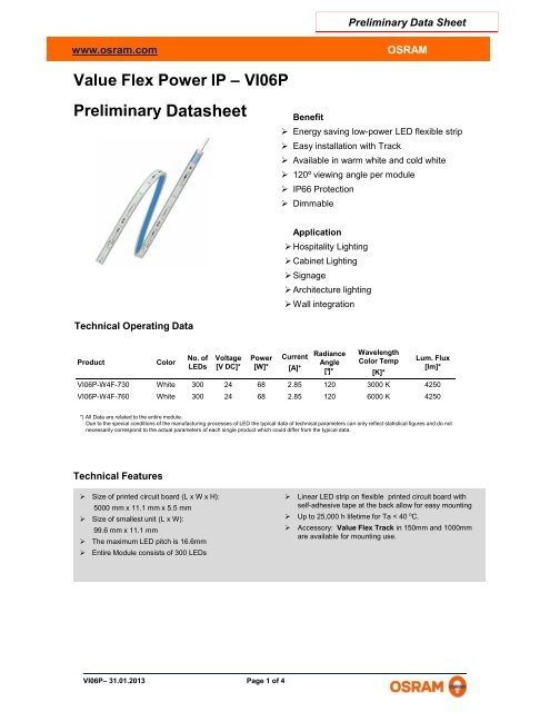
Preliminary Data Sheetwww.osram.comOSRAM<strong>Value</strong> <strong>Flex</strong> <strong>Power</strong> IP – <strong>VI06P</strong>Preliminary <strong>Datasheet</strong>Benefit Energy saving low-power LED flexible strip Easy installation with Track Available in warm white and cold white 120º viewing angle per module IP66 <strong>Protect</strong>ion DimmableApplication Hospitality Lighting Cabinet Lighting Signage Architecture lighting Wall integrationTechnical Operating DataProductColorNo. of Voltage <strong>Power</strong> CurrentRadianceAngleLEDs [V DC]* [W]* [A]*[°]*WavelengthColor Temp[K]*Lum. Flux[lm]*<strong>VI06P</strong>-W4F-730 White 300 24 68 2.85 120 3000 K 4250<strong>VI06P</strong>-W4F-760 White 300 24 68 2.85 120 6000 K 4250*) All Data are related to the entire module.Due to the special conditions of the manufacturing processes of LED the typical data of technical parameters can only reflect statistical figures and do notnecessarily correspond to the actual parameters of each single product which could differ from the typical data.Technical FeaturesSize of printed circuit board (L x W x H):5000 mm x 11.1 mm x 5.5 mmSize of smallest unit (L x W):99.6 mm x 11.1 mmThe maximum LED pitch is 16.6mmEntire Module consists of 300 LEDsLinear LED strip on flexible printed circuit board withself-adhesive tape at the back allow for easy mounting Up to 25,000 h lifetime for Ta < 40 o C.Accessory: <strong>Value</strong> <strong>Flex</strong> Track in 150mm and 1000mmare available for mounting use.<strong>VI06P</strong>– 31.01.2013 Page 1 of 4
Preliminary Data Sheetwww.osram.comOSRAMMinimum / Maximum RatingsProductOperating Temperatureat Tc-Point [°C]*StorageTemperature [°C]*Voltage Range[V dc]*Reverse Voltage[V dc]*<strong>VI06P</strong>-W4F-730 -20 … 60 -25 … 85 23 … 25 25<strong>VI06P</strong>-W4F-760 -20 … 60 -25 … 85 23 … 25 25*) Exceeding maximum ratings for operating and storage temperature will reduce expected life time or destroy the LED Modules.Exceeding maximum ratings for operating voltage will cause hazardous overload and will likely destroy the LED Modules.The temperature of the LED modules must be measured at the Tc-point according to EN60598-1 in a thermally constant status with a temperature sensor or a temperaturesensitive label.Dimensions<strong>Value</strong> <strong>Flex</strong> <strong>Power</strong> IPAccessory – <strong>Value</strong> <strong>Flex</strong> IP Track 150mm/1000mm<strong>VI06P</strong>– 31.01.2013 Page 2 of 4
Preliminary Data Sheetwww.osram.comOSRAMSafety InformationThe LED module itself and all its components must not be mechanically stressed.Assembly must not damage or destroy conducting paths on the circuit board.To avoid mechanical damage, the LED modules should be attached securely to the intended substrate. Heavy vibrationshould be avoided.The LED module incorporates no protection against short circuits, overload or overheating.In order to drive OSRAM LED-Modules safely, it is absolutely necessary to operate them with an electronicallystabilized power supply protecting against short circuits, overload and overheating.For dimming applications attention should be paid to specific references in “OPTOTRONIC ® Technical Guide”.To also ease the luminaire/installation approval, electronic control gear for LED or LED modules must carry the CE mark.In Europe the declarations of conformity must include the following standards:CE: EN 61347-2-13, EN 55015, EN 61547 and EN 61000-3-2.Also check for the mark of an independent authorized certification institute.Please see the relevant application guides for more detailed information.When using power supplies other than OPTOTRONIC ® the following basic safety features are required, in addition to anyother application specific concerns and local safety codes.OSRAM OPTOTRONIC® electronic control gear complies to all relevant standards and guarantees safe operation.Installation of LED modules (with power supplies) needs to be made with regard to all applicable electrical and safetystandards. Only qualified personnel should be allowed to perform installations.Observe correct polarity! Incorrect polarity will lead to no light emission.Parallel connection is highly recommended as safe electrical operation mode. Serial connection is not recommended.Unbalanced voltage drop can cause hazardous overload and damage the LED module.OTe 90/220-240/24 E can contact 1 reels of <strong>VI06P</strong>, power feed at one end of each reel of flex.When mounting on metallic or otherwise conductive surfaces, there needs to be a electrical isolation at soldering pointsbetween module and the mounting surface,Pay attention to ESD steps when mounting the module.Please ensure that the power supply is of adequate power to operate the total load.LED modules are dimmable by means of PWM (pulse width modulation). It is recommended using the following OSRAMcontrol gears: OPTOTRONIC® OT DIM, OT DALI DIM, OT DALI DIM LI.Damage by corrosion will not be honored as a materials defect claim. It is the user’s responsibility to provide suitableprotection against corrosive agents such as moisture and condensation and other harmful elements.<strong>VI06P</strong>– 31.01.2013 Page 3 of 4
Preliminary Data Sheetwww.osram.comOSRAMAssembly InformationConnection with soldering wires on unmounted module: Do not pre-tin the solder pads but pre-tin the wires and solder formax 4s at 300 o C. Allow solder points to completely cool down before the next soldering. Prevent shear- or peel forces. Soldering of wires with the module mounted on a heat sink: Pre-tin solder pads and wires and solder for max 3s at 350 o C.Allow solder points to completely cool down before the next soldering. Prevent shear- or peel forces.The smallest unit (99.6 mm – 6 LEDs) can be removed by cutting with scissors between the designated solder pads.The mounting of the module is facilitated by means of the double-sided adhesive on the back-surface of the module. Caremust be taken to provide a clean and dry mounting surface, free of oils or silicone coatings as well as dirt particle. Themounting substrate must have sufficient structural integrity. Take care to completely remove the protective backing. Oncethe module is appropriately positioned, press on the module with about 20N/cm2 (refer to application techniques of 3Madhesive transfer tapes). In difficult cases the use of a primer may help.The minimum bending radius is 5cm.Ordering GuideProduct group Product name EAN S-Unit*<strong>Value</strong> <strong>Flex</strong> <strong>Power</strong> IP 3000K <strong>VI06P</strong>-W4F-730 4008321870162 8 pcs<strong>Value</strong> <strong>Flex</strong> <strong>Power</strong> IP 6000K <strong>VI06P</strong>-W4F-760 4008321870407 8 pcs1000mm <strong>Value</strong> <strong>Flex</strong> IP Track VI-TR1000 TBC 20 pcs150mm <strong>Value</strong> <strong>Flex</strong> IP Track VI-TR150 TBC 20 pcs* EAN: Ordering number per single sale unit* S-Unit: Modules / accessory number per shipping unitNote: Typical performance data are subject to change without any further notice, particularly as LED technology evolves.Sales and Technical SupportOSRAM Asia Pacific30 th Floor, China Resources Building26 Harbour Road, WanChai, Hong Kongwww.osram.comSales and technical support is given by thelocal OSRAM subsidiaries.On our world wide homepage all OSRAMsubsidiaries are listed with complete addressand phone numbers.<strong>VI06P</strong>– 31.01.2013 Page 4 of 4