Owners Manual - Air Compressors Direct
Owners Manual - Air Compressors Direct
Owners Manual - Air Compressors Direct

You also want an ePaper? Increase the reach of your titles
YUMPU automatically turns print PDFs into web optimized ePapers that Google loves.
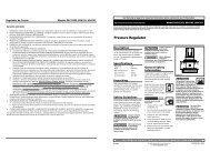
POCKET CLIPSLIDINGRUBBER O-RINGSDEFLECTIONFORCE SCALE(READ DOWN)DEFLECTIONDISTANCESCALE(READ UP)Fig. 5-2 Belt Tension GaugePix 1153PRESSUREADJUSTMENTSCREWELECTRICALCONTACTSStep 2) Determine the amount of deflection (in inches) required to measure deflection force (inpounds) by multiplying the span length x 1 / 64(.016)(i.e. 32” span length x 1 / 64[.016] = 1 / 2”[.50] of deflectionrequired to measure deflection force).Step 3) Lay a straightedge across the top outersurface of a drive belt from pulley to sheave.Step 4) At the center of the span, perpendicularto the belt, apply pressure to the outer surfaceof the belt with a belt tension gauge (refer to Fig.5-2, Belt Tension Gauge). Force the belt to thepredetermined deflection (refer to Step 2 above).Record the reading on the belt tension gauge andcompare to the chart following Fig 5-1. The deflectionforce reading should be within the minimumand maximum values shown. Adjust belt(s)accordingly. New belts should be initially tensionedto the maximum value plus 33% (multiply by 1.33).Step 5) Recheck the tension of the new beltsseveral times in the first 50 hours of operation andadjust if necessary. Thereafter, check belt tensionon a regular basis (refer to SECTION 5, MaintenanceSchedule).Pressure Switch AdjustmentPressure switches provided by Quincy Compressorare pre-set at the factory and usually do notrequire adjustment. However, the following procedurescan be performed by a qualified electricianto adjust the pressure switch.Fig. 5-3 Pressure SwitchPix 1067Step 1)Remove the pressure switch cover.Step 2) While the compressor is running, screwthe spring loaded adjustment screw in (clockwise)to increase the amount of air pressure required to open the switchand stop the unit. Screw the spring loaded adjustment screw out(counterclockwise) to decrease the amount of air pressure requiredto open the switch and stop the unit.Standard pressure switches supplied by Quincy Compressor are equippedwith a fixed 20 PSIG (approx.) differential. Optional switches include bothpressure and differential adjustment capabilities.WARNING !Electric power always exists inside the pressure switch wheneverthe compressor package is connected to a power supply. Be carefulnot to touch any electrical leads when adjusting the pressureswitch.QT & PLT SeriesQuincy Compressor50161-106, January 2009 31 3501 Wismann Lane, Quincy Ill. - 62305-3116