Atmospheric Pressure Non-thermal Plasma in Flexible Tubings
Atmospheric Pressure Non-thermal Plasma in Flexible Tubings
Atmospheric Pressure Non-thermal Plasma in Flexible Tubings
- No tags were found...
You also want an ePaper? Increase the reach of your titles
YUMPU automatically turns print PDFs into web optimized ePapers that Google loves.
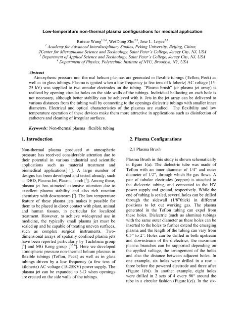
Low-temperature non-<strong>thermal</strong> plasma configurations for medical applicationRuixue Wang 1,3,4 , WeiDong Zhu 2,3 , Jose L. Lopez 2,31 Academy for Advanced Interdiscipl<strong>in</strong>ary Studies, Pek<strong>in</strong>g University, Beij<strong>in</strong>g, Ch<strong>in</strong>a;2Center for Microplasma Science and Technology, Sa<strong>in</strong>t Peter’s College, Jersey City, NJ, USA3 Department of Applied Science and Technology, Sa<strong>in</strong>t Peter’s College, Jersey City, NJ, USA4 Department of Physics, Polytechnic Institute of NYU, Brooklyn, NY, USAAbstract<strong>Atmospheric</strong> pressure non-<strong>thermal</strong> helium plasmas are generated <strong>in</strong> flexible tub<strong>in</strong>gs (Teflon, Peek) aswell as <strong>in</strong> glass tub<strong>in</strong>gs. <strong>Plasma</strong> is ignited when a low frequency (a few tens of kilohertz) AC voltage (15-25 kV) was supplied to two annular electrodes on the tub<strong>in</strong>g. “<strong>Plasma</strong> brush” (or plasma jet array) isrealized by open<strong>in</strong>g circular holes on the side walls of the tub<strong>in</strong>gs. Individual ballast<strong>in</strong>g on each hole isnot necessary, although better stability can be achieved with it. Jets <strong>in</strong> the jet array can be delivered tovarious distances from the tub<strong>in</strong>g wall by connect<strong>in</strong>g to the open<strong>in</strong>gs dielectric tub<strong>in</strong>gs with smaller <strong>in</strong>nerdiameters. Electrical and optical characteristics of the plasmas are studied. The flexibility and lowtemperature operation of these devices make them more attractive <strong>in</strong> applications such as dis<strong>in</strong>fection ofcatheters and clean<strong>in</strong>g of irregular surfaces.Keywords: <strong>Non</strong>-<strong>thermal</strong> plasma flexible tub<strong>in</strong>g1. Introduction<strong>Non</strong>-<strong>thermal</strong> plasma produced at atmosphericpressure has received considerable attention due totheir potential <strong>in</strong> various <strong>in</strong>dustrial and scientificapplications such as material treatment andbiomedical applications[ 1 ]. A large number ofdesigns has been developed and tested already, suchas DBD, <strong>Plasma</strong> Jet, <strong>Plasma</strong> Torch [ 2 ]. Among these,plasma jet has attracted extensive attention due toexcellent plasma stability and also rich reactionchemistry with downstream [ 3 ]. The low temperaturefeature of these plasma jets makes it possible forthem to be placed <strong>in</strong> direct contact with plant, animaland human tissues, <strong>in</strong> particular for localizedtreatment. However, to achieve widespread use <strong>in</strong>medic<strong>in</strong>e, the typically small plasma jet must bescaled up and be capable of treat<strong>in</strong>g uneven surfaces,such as complex surgical <strong>in</strong>struments. Twodimensionalarrays of spatially conf<strong>in</strong>ed plasma jetshave been reported particularly by Tachibana group[ 4 ] and MG Kong group [ 3,5,6 ]. Here we developedatmospheric pressure non-<strong>thermal</strong> helium plasmas <strong>in</strong>flexible tub<strong>in</strong>gs (Teflon, Peek) as well as <strong>in</strong> glasstub<strong>in</strong>gs driven by a low frequency (a few tens ofkilohertz) AC voltage (15-25KV) power supply. Theplasma jet can be expanded to 3-D when open<strong>in</strong>gsare created on the side walls of the tub<strong>in</strong>gs.2. <strong>Plasma</strong> Configurations2.1 <strong>Plasma</strong> Brush<strong>Plasma</strong> Brush <strong>in</strong> this study is shown schematically<strong>in</strong> figure 1(a). The dielectric tube was made ofTeflon with an <strong>in</strong>ner diameter of 1/4” and outerdiameter of 1/2”, through which He gas flows. Apair of tubular electrodes (copper) is attached tothe dielectric tub<strong>in</strong>g, and connected to the HVpower supply and ground, respectively. While theend of tub<strong>in</strong>g is sealed, several holes can be drilledthrough the sidewall (1/8”thick) <strong>in</strong> differentpositions to let out work<strong>in</strong>g gas. The plasmagenerated <strong>in</strong> the Teflon tub<strong>in</strong>g can expel fromthese holes. Dielectric (such as alum<strong>in</strong>a) tub<strong>in</strong>gswith the same outer diameter as these holes can be<strong>in</strong>serted to the holes to further extend the emerg<strong>in</strong>gplasma and the length of the tub<strong>in</strong>g can vary from0.5” to 2”. Holes can be drilled <strong>in</strong> both upstreamand downstream of the dielectrics, the maximumplasma branches can be supported depend<strong>in</strong>g onthe applied voltage, the arrangement of the holesand also the distance between adjacent holes. Inone example, six holes were drilled <strong>in</strong> a row –three before the powered electrode and three after(Figure 1(b)). In another example, eight holeswere drilled <strong>in</strong> 2 sets of 4 every 90° around thetube <strong>in</strong> a circular fashion (Figure1(c)). In the six-
hole case, all of the alum<strong>in</strong>a tub<strong>in</strong>gs can be ignited(have a visible plasma jet) except the one <strong>in</strong> themiddle of upstream. The plasma started betweenthe two tubular electrodes and then spread to thebranches when voltage was <strong>in</strong>creased.(a)((b)(c)emissions from NO, N 2 , N 2(Figure 3 (b) <strong>in</strong>set),He and O.Current(mA)0.030.020.010.00-0.01-0.02ABCDEF151050-5-10Voltage(KV)-0.03-15Figur .1. (a) Schematic diagrams of the plasma brush; (b)ignited plasma brush with six holes and (c) 2 sets of 4 every90° holes around the tube2.2 Characterization of plasma brushThe electrical characteristics of the plasma brushwere evaluated with a high voltage probe(Tektronix 6015A) connected to the poweredelectrode and a current probe (Pearson 6585)placed at six different locations (A-F, as noted <strong>in</strong>figure 1(a)). The results at V p =10 kV without anyballast<strong>in</strong>g capacitor are shown <strong>in</strong> figure 2. Thedischarge currents at all six locations are more orless the same. One current pulse is observed forevery half cycle of the applied voltage, whichresembles what was typically observed <strong>in</strong>dielectric-barrier discharges [ 7 ].Optical emission was monitored via amonochromater (Pr<strong>in</strong>ceton Instrument Acton 2750)connected with an Intensified Charge CoupledDevice camera (Pr<strong>in</strong>ceton Instrument IMAX-1024)at alum<strong>in</strong>a port A and B (as noted <strong>in</strong> figure 1 (a))to determ<strong>in</strong>e the composition of the plasma. Thelight was <strong>in</strong>troduced via a quartz fiber opticsbundle placed at ~1 cm away from the exit of thealum<strong>in</strong>a tub<strong>in</strong>gs. Figure 3 shows the emissionspectra taken at these two locations. The overallemission <strong>in</strong>tensity from A (downstream) is higherthan that from B (upstream) although sameemission l<strong>in</strong>es are found <strong>in</strong> both. Identifiable are-20 0 20 40 60 80 100Time(ns)Figure 2. Voltage (blue) and currents for plasma brush <strong>in</strong>different position (as noted <strong>in</strong> figure 1 (a))Emission Intensity(a.u)1000000800000600000400000200000010000008000006000004000000A_dowstream(a)200000 (b)B_upstream200 250 300 350 400 450200 300 400 500 600 700 800 900Wavelength(nm)Figure 3. Optical Emission Spectra taken at alum<strong>in</strong>a port(a) A (downstream) and (b) B (upstream) (A and B are asnoted <strong>in</strong> figure 1 (a)). Inset: light emission from 200-450nmshow<strong>in</strong>g emission from NO, N 2 and N 2+2.3 <strong>Plasma</strong> <strong>in</strong> various forms <strong>in</strong> TeflonIntensity(A.U)<strong>Plasma</strong> can be generated <strong>in</strong> flexible tub<strong>in</strong>gs madeof Teflon or Peek (OD: ¼” and ID: ½”). Figure 4(a) and (b) show helium plasma generated <strong>in</strong> as<strong>in</strong>gle loop and a spiral tub<strong>in</strong>g arrangement. Forthe s<strong>in</strong>gle loop arrangement (Figure 4 (a)), heliumwas <strong>in</strong>troduced through a three way <strong>in</strong>sulat<strong>in</strong>gconnector and evenly spread to both branches.Light emission from one branch appears to bestronger than the other due to the electrode120000100000800006000040000200000N 2N + 22 +1 -NOv=0(0,0)v=-1v=-2Wavelength(nm)(2,3)(1,2)(0,1)(3,5)(2,4)(1,3)(0,2)(3,6)(2,5)(1,4)(0,3)(3,7)(2,6)(1,5)(0,4)(2,2)(1,1)(0,0)v=-3v=0v=-4(4,5)(2,3)(1,2)(0,1)
arrangement. At the far end of the loop, anopen<strong>in</strong>g was made and connected to an alum<strong>in</strong>atube, where a plasma jet was created as expected.For the spiral tub<strong>in</strong>g case, helium plasma couldnot bend over one s<strong>in</strong>gle loop if the copperelectrode was attached only to a section on oneloop. A strip of copper electrode (1” wide) wasthen attached across all loops. A seem<strong>in</strong>glycont<strong>in</strong>uous plasma through the spiral tub<strong>in</strong>g wasthen generated (Figure 4 (b)).alum<strong>in</strong>a rank<strong>in</strong>g the highest <strong>in</strong> the materials used <strong>in</strong>this study). Charge accumulation eventually reacheda critical value at which the electric field was strongenough to break down air around it at the presenceof a third electrode.(a)(a)He gas(b)PoweredelectrodeFigure 4. <strong>Plasma</strong> generated <strong>in</strong> (a) a s<strong>in</strong>gle loop and (b)spiral tub<strong>in</strong>g2.4 <strong>Plasma</strong> with a third electrodeIt has been well documented that these heliumplasmas can be generated <strong>in</strong> glass/quartz tub<strong>in</strong>gs atvarious diameters [ 8 , 9 ]. We repeated thoseexperiments <strong>in</strong> glass tub<strong>in</strong>gs of different sizes: 1) ID:0.218” and OD: 3/8”; 2) ID: 0.312”, OD: 0.5” and 3)ID: 0.376” and OD: 0.5” with our AC power supply.The appearance of the plasma <strong>in</strong> the glass tub<strong>in</strong>g ishighly dependent on the size of the tub<strong>in</strong>g and the<strong>in</strong>put voltage. At a low voltage, the lum<strong>in</strong>escence ofthe plasma is conf<strong>in</strong>ed to an axial filament ofdiameter below 1 mm at the center of the tub<strong>in</strong>g (asshown <strong>in</strong> figure 5 (a), dashed l<strong>in</strong>e represents theglass boundary). The diameter as well as thebrightness of the filament <strong>in</strong>crease with the appliedvoltage. At a voltage of V p = 25 kV, the plasma fillsthe whole glass tube with the axial filamentrema<strong>in</strong><strong>in</strong>g at the center (as shown <strong>in</strong> figure 5 (b).Also worth not<strong>in</strong>g is that at approximately the samepeak voltage, when a metal object (such as a razorblade or a round head hex Allen wrench) wasbrought close to the glass tub<strong>in</strong>g wall, far away fromthe powered electrode (either upstream ordownstream), air breakdown was observed. Thisphenomenon was more clearly observed whenceramic tub<strong>in</strong>gs were used (as shown <strong>in</strong> figure 5 (c)and (d)). It is very likely that charges <strong>in</strong> the plasmaaccumulated on the tub<strong>in</strong>g walls, which wasessentially proportional to the applied voltage andthe dielectric constant of the tub<strong>in</strong>g material (withFigure 5.<strong>Plasma</strong> generated <strong>in</strong> glass tub<strong>in</strong>g (ID: 0.218,OD:03/8”) at (a) V p = 7 kV: a clear axial filament is seen and (b)V p = 25 kV: plasma fills the whole glass with an axial filamentpresent; Air break down outside of the alum<strong>in</strong>a tub<strong>in</strong>gs wereobserved at V p = 25 kV when (c) a razor blade and (d) a roundhead hex Allen wrench was brought closeFigure 6. At V p =7 kV, a spiral shape plasma developswhen a round head hex Allen wrench is brought close tothe glass tub<strong>in</strong>gIn the case of lower voltage (V p =7 kV) while theplasma was still susta<strong>in</strong>ed, no air break wasobserved. However, when mov<strong>in</strong>g close a roundhead hex Allen wrench, a spiral shape plasmaform along the <strong>in</strong>ner surface of the tub<strong>in</strong>g (Figure6). This could be that the electric field due to thecharges accumulated on the tub<strong>in</strong>g walls be<strong>in</strong>glocally perturbed by the metal item. Further<strong>in</strong>vestigation of this phenomenon is underway. Ithas to be noted that this spiral shape plasmaappears only toward the grounded electrode or <strong>in</strong>
the case of the gas was expelled <strong>in</strong>to air, it appearstoward the tub<strong>in</strong>g open<strong>in</strong>g (where we consider as avirtual ground). Meanwhile, the filament <strong>in</strong> themiddle of the tub<strong>in</strong>g became weak but still visible.ConclusionIn conclusion, we demonstrated the generationof helium plasma <strong>in</strong> flexible tub<strong>in</strong>gs as well as <strong>in</strong>glass tub<strong>in</strong>gs. The plasma can be split <strong>in</strong>to manybranches by open<strong>in</strong>g holes on flexible tub<strong>in</strong>gs.OES show emission mostly from NO, N 2 , N 2 + ,He and O. The appearance of the plasma <strong>in</strong> glasstub<strong>in</strong>g depended on the size of the tub<strong>in</strong>g andthe applied voltage. Clear axial filament wereobserved at both high voltage (V p =25 kV) andlow voltage (V p =7 kV). At V p =25 kV, airbreakdown between the tub<strong>in</strong>g and thirdelectrode was observed due to the strong electricfield from the accumulated charged on thetub<strong>in</strong>g walls. Different plasma geometry and lowtemperature property make it suitable formedical applications where <strong>in</strong>struments withirregular surfaces are <strong>in</strong>volved.Acknowledgement(b) (d)This research was funded <strong>in</strong> part by the Electro-Energetic Physics Program of the U.S. Air ForceOffice of Scientific Research (AFOSR) undergrant number FA9550-08-1-0332.Acknowledgment is also made to the Donors ofthe American Chemical Society PetroleumResearch Fund and Council Scholarship ofCh<strong>in</strong>a for support of this research. RW wouldlike to thank Drs. Jue Zhang and J<strong>in</strong>g Fang fortheir constructive advices.and gas flow fields for three-dimensional surfacetreatment. APL. 94, 021501(2009)4 O Sakai, T Sakaguchi and K Tachibana.Photonic bands <strong>in</strong> two-dimensional microplasmaarrays.I. Theoretical derivation of bandstructures of electromagnetic waves. JAP 101,073304(2007).5 QY Nie, Z Cao, C S Ren, DZ Wang and MGKong. A two-dimensional cold atmosphericplasma jet array for uniform treatment of largeareasurfaces for plasma medic<strong>in</strong>e. NJP. 11(2009)115015.6 Z Cao, Q Nie, DL Bayliss, JL Walsh, CS Ren,DZ Wang and MG Kong. Spatially extendedatmospheric plasma arrays. PPST. 19(2010)0250030.7 U Kogelschatz, Dielectric-barrier Discharges:Their History, Discharge Physics, and IndustrialApplications. <strong>Plasma</strong> Chemistry and <strong>Plasma</strong>Process<strong>in</strong>g. Vol.23, No1, March 2003.8KD Weltmann, R Brandenburg, T vonWoedtke, J Ehlheck, R Foest, M Stieber and EK<strong>in</strong>del. Antimicrobial treatment of heat sensitiveproducts by m<strong>in</strong>iaturized atmospheric pressureplasma jets(APPPs). J.Phys.D: Appl.Phys.41(2008)1940089 N Jiang, A Ji and Z Cao, <strong>Atmospheric</strong> pressureplasma jet: Effect of electrode configuration,discharge behavior, and its formationmechanism. JAP, 2009.References1 K.H.Becker, U.Kogelschatz, K.H.Schoenbach,and R.J.Barker, <strong>Non</strong>-Equilibrium Air <strong>Plasma</strong> at<strong>Atmospheric</strong> <strong>Pressure</strong>(IOP, Bristol, 2004)2 M G Kong, G Kroesen, G Morfill, T Nosenko,T Shimizu, J van Dijk and J L Zimmermann.<strong>Plasma</strong> medic<strong>in</strong>e: an <strong>in</strong>troductory review. NewJ.Phys. 11(2009) 115012.3 Z. Cao, J.L. Walsh, and M.G. Kong.<strong>Atmospheric</strong> plasma jet array <strong>in</strong> parallel electric


