Deposition of carbide and nitride based composite coating by ...
Deposition of carbide and nitride based composite coating by ...
Deposition of carbide and nitride based composite coating by ...

Create successful ePaper yourself
Turn your PDF publications into a flip-book with our unique Google optimized e-Paper software.
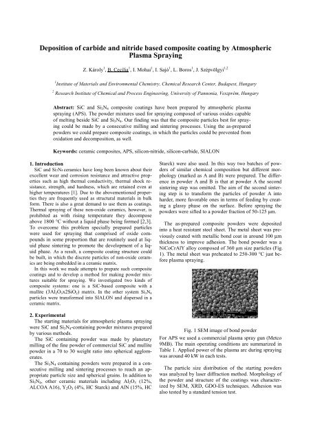
<strong>Deposition</strong> <strong>of</strong> <strong>carbide</strong> <strong>and</strong> <strong>nitride</strong> <strong>based</strong> <strong>composite</strong> <strong>coating</strong> <strong>by</strong> AtmosphericPlasma SprayingZ. Károly 1 , B. Cecília 1 , I. Mohai 1 , I. Sajó 1 , L. Boros 1 , J. Szépvölgyi 1,21 Institute <strong>of</strong> Materials <strong>and</strong> Environmental Chemistry, Chemical Research Center, Budapest, Hungary2 Research Institute <strong>of</strong> Chemical <strong>and</strong> Process Engineering, University <strong>of</strong> Pannonia, Veszprém, HungaryAbstract: SiC <strong>and</strong> Si 3 N 4 <strong>composite</strong> <strong>coating</strong>s have been prepared <strong>by</strong> atmospheric plasmaspraying (APS). The powder mixtures used for spraying composed <strong>of</strong> various oxides capable<strong>of</strong> melting beside SiC <strong>and</strong> Si 3 N 4 . Our finding was that the <strong>composite</strong> particles best for sprayingcould be made <strong>by</strong> a consecutive milling <strong>and</strong> sintering processes. Using the as-preparedpowders we could prepare <strong>composite</strong> <strong>coating</strong>s, in which the particles could be prevented fromoxidation <strong>and</strong> decomposition, as well.Keywords: ceramic <strong>composite</strong>s, APS, silicon-<strong>nitride</strong>, silicon-<strong>carbide</strong>, SIALON1. IntroductionSiC <strong>and</strong> Si3N4 ceramics have long been known about theirexcellent wear <strong>and</strong> corrosion resistance <strong>and</strong> attractive propertiessuch as high thermal conductivity, thermal shock resistance,strength, <strong>and</strong> hardness, which are retained even athigher temperatures [1]. Due to the abovementioned propertiesthey are frequently used as structural materials in bulkform. There is also a great dem<strong>and</strong> to use them as <strong>coating</strong>s.Thermal spraying <strong>of</strong> these non-oxide ceramics, however, isprohibited as with rising temperature they decomposeabove 1800 °C without a liquid phase being formed [2,3].To overcome this problem specially prepared particleswere used for spraying that comprised <strong>of</strong> oxide compoundsin some proportion that are routinely used at liquidphase sintering to promote the development <strong>of</strong> a liquidphase. As a result, a <strong>composite</strong> <strong>coating</strong> structure couldbe built, in which the discrete particles <strong>of</strong> non-oxide ceramicsare being embedded in a ceramic matrix.In this work we made attempts to prepare such <strong>composite</strong><strong>coating</strong>s <strong>and</strong> to develop a method for making powder mixturessuitable for spraying. We investigated two kinds <strong>of</strong><strong>composite</strong> systems: one is a SiC-<strong>based</strong> <strong>composite</strong> with amullite (3Al 2 O 3 x2SiO 2 ) matrix. In the other system Si 3 N 4particles were transformed into SIALON <strong>and</strong> dispersed in aceramic matrix.2. ExperimentalThe starting materials for atmospheric plasma sprayingwere SiC <strong>and</strong> Si 3 N 4 -containing powder mixtures prepared<strong>by</strong> various methods.The SiC containing powder was made <strong>by</strong> planetarymilling <strong>of</strong> the fine powder <strong>of</strong> commercial SiC <strong>and</strong> mullitepowder in a 70 to 30 weight ratio into spherical agglomerates.The Si 3 N 4 containing powders were prepared in a consecutivemilling <strong>and</strong> sintering processes to reach an appropriateparticle size <strong>and</strong> spherical grains. In addition toSi 3 N 4 , other ceramic materials including Al 2 O 3 (12%,ALCOA A16), Y 2 O 3 (4%, HC Starck) <strong>and</strong> AlN (15%, HCStarck) were also used. In this way two batches <strong>of</strong> powders<strong>of</strong> similar chemical composition but different morphology(marked as A <strong>and</strong> B) were prepared. The differencein powder A <strong>and</strong> B is that at powder A the secondsintering step was omitted. The aim <strong>of</strong> the second sinteringstep is to transform the particles <strong>of</strong> powder A intoharder, more favorable ones in terms <strong>of</strong> feeding <strong>by</strong> creatinga glassy phase on the surface. Before spraying thepowders were sifted to a powder fraction <strong>of</strong> 50-125 µm.The as-prepared <strong>composite</strong> powders were depositedinto a heat resistant steel sheet. The metal sheet was previouslycoated with metallic bond coat in around 100 µmthickness to improve adhesion. The bond powder was aNiCoCrAlY alloy composed <strong>of</strong> 360 µm size particles (Fig.1). The metal sheet was preheated to 250-300 °C just beforeplasma spraying.Fig. 1 SEM image <strong>of</strong> bond powderFor APS we used a commercial plasma spray gun (Metco9MB). The main operating conditions are summarized inTable 1. Applied power <strong>of</strong> the plasma arc during sprayingwas around 40 kW in each tests.The particle size distribution <strong>of</strong> the starting powderswas analyzed <strong>by</strong> laser diffraction method. Morphology <strong>of</strong>the powder <strong>and</strong> structure <strong>of</strong> the <strong>coating</strong>s was characterized<strong>by</strong> SEM, XRD, GDO-ES techniques. Adhesion wasalso tested <strong>by</strong> a st<strong>and</strong>ard tension test.
Table 1. Operating conditions <strong>of</strong> sprayed powders I.PowdersBond <strong>coating</strong>Mullit - SiCPowder A <strong>and</strong> BGases( l·min -1 )Plasma: Ar(42)H 2 (5.2)Carrier: Ar (8)Plasma: Ar (40)H 2 (6)Carrier: Ar (12)Plasma: Ar (38)H 2 (13)Carrier: Ar (7)Spraydistance[mm]1003. ResultsMullite-SiC nano<strong>composite</strong>During plasma spraying <strong>of</strong> <strong>carbide</strong> containing powdermixture we face two risks. One is the oxidation <strong>of</strong> SiCparticles on getting into contact with air at elevated temperature.The other one is the possible decomposition <strong>of</strong>SiC at the high temperature <strong>of</strong> the plasma flame. The injectedpowder, however, should be subjected to hightemperature as the mullite, which is the matrix formingcomponent <strong>of</strong> the <strong>composite</strong> ceramic <strong>coating</strong> melts onlyabove 1850 °C [4]. Comparing the XRD diffractograms<strong>of</strong> the starting powder mixture <strong>and</strong> the coated substrate noconsiderable changes occurred. Only the characteristicpeaks <strong>of</strong> mullite, alumina <strong>and</strong> SiC can be revealed on theX-ray diffractogram <strong>of</strong> the <strong>coating</strong> (Fig. 2). It means thatboth the oxidation <strong>and</strong> the decomposition could be preventedas biggest part <strong>of</strong> the plasma energy was used tomelting <strong>of</strong> the mullite particles.7065whole numbers in Fig. 3. Evaluating the relative ratio <strong>of</strong>the chemical elements we can roughly determine the interface<strong>of</strong> the substrate/bond <strong>and</strong> the bond/ceramic <strong>coating</strong>,which are situated at points 3 <strong>and</strong> 2, respectively.Continuous chemical analyses in respect to distance fromthe front <strong>of</strong> the <strong>coating</strong> could be made <strong>by</strong> GD-OESanalyses. The resulted curves <strong>of</strong> the constituent chemicalelements are illustrated in Fig. 4. The quickly decreasingSi line suggests that the ceramic <strong>coating</strong> was actually only50 µm thick, while the much thicker bond layer comes toend after 140 µm. It is followed <strong>by</strong> a 40 µm thick zone inwhich the Ni content is decreasing with increasing Fecontent. This zone was probably formed during sprayingdue to diffusion at the elevated temperature <strong>of</strong> the substrate.As oxygen could not be detected in the bond coat,oxidation <strong>of</strong> this metallic layer could be avoided. Theobvious contradiction <strong>of</strong> the results <strong>of</strong> the presented twomethods is possibly caused <strong>by</strong> the not uniform thickness<strong>of</strong> the <strong>coating</strong> due to manual spraying.mullitmullitmullit+SiCSiCFig. 3 SEM image <strong>of</strong> the cross section <strong>of</strong> SiC-<strong>based</strong><strong>coating</strong>SiC+ mullitmullitmullitmullitmullitmullitMullit+AL2O3mullitmullitmullitmullitSiCmullitAL3NiAl3NiFig. 2 XRD diffractogram <strong>of</strong> SiC-<strong>based</strong> <strong>coating</strong>SEM micrograph <strong>of</strong> the cross section <strong>of</strong> the <strong>coating</strong> isshown in Fig. 2. The thickness <strong>of</strong> the <strong>coating</strong> can be estimatedto be about 200 µm. To determine the thicknessmore precisely, we have made chemical analysis on thecross section <strong>of</strong> the coated substrate <strong>by</strong> different methods.EDS analyses were carried out at the spots marked withFig. 4 Concentration <strong>of</strong> the elements along the crosssection <strong>of</strong> the SiC-<strong>based</strong> <strong>composite</strong> <strong>coating</strong> <strong>by</strong> GD-OES
Si 3 N 4 -<strong>based</strong> nano<strong>composite</strong>sSEM micrographs <strong>of</strong> powders A <strong>and</strong> B (Fig. 5 a, b)show that the applied procedure resulted in homogenous<strong>and</strong> large particles. At higher magnification it can be observedthat the powder mixture sintered twice (B) iscomposed <strong>of</strong> hardly round particles having several edgesin contrast to powder A, which was not subjected to asecond sintering step. Additional work will be requiredbefore underst<strong>and</strong>ing <strong>of</strong> this unexpected result. Accordingto laser diffraction size analysis, both powders (i.e. A <strong>and</strong>B) are composed <strong>of</strong> particles with size between 50-110µm. The efficiency <strong>of</strong> the second sintering step was verifiedas particles <strong>of</strong> powder B did not broke apart on theeffect <strong>of</strong> ultrasonic agitation in contrast to powder A.Even so, powder A did not brake up during feeding,what’s more it could be fed much better than powder B.XRD diffractograms suggest that particles are principallycomposed <strong>of</strong> crystalline phases, including yttriumaluminum oxide (40%), corundum <strong>and</strong> β-SIALON(20-20%). Considerable oxidation <strong>of</strong> the powders couldbe prevented in spite <strong>of</strong> the high temperature <strong>of</strong> the furnace.Coatings made <strong>by</strong> plasma sprayingThe thickest <strong>coating</strong> was prepared using powder A (300µm), whilst using powder B the obtained thickness wasonly ~100 µm. During spraying <strong>of</strong> powder B the feedingwas not uniform probably due to the aforementioned unfavorablemorphology, which eventually resulted in severallarger non-melted agglomerates embedded in the<strong>coating</strong>.. Seemingly perfect uniform <strong>coating</strong> formed usingpowder A. Peaks on the XRD diffractograms (Fig. 6) correspondto the crystalline phases <strong>of</strong> β-SIALON, corundum,YAG <strong>and</strong> yttrium-oxide in an estimated amount <strong>of</strong>30, 30, 10 <strong>and</strong> 3 wt%, respectively. In addition, a considerableamount <strong>of</strong> glassy phase (30%) was also present.Comparing this results with the phase composition <strong>of</strong> thestarting material (Fig. 7) it can be concluded that mostlythe YAG phase was vitrified while corundum <strong>and</strong> theβ-SIALON retained its crystalline characteristic.Adhesion was tested <strong>by</strong> tensile adhesion test accordingto st<strong>and</strong>ard MSZ EN ISO 4624:2003. In this test thecoated sample is glued to an uncoated counterpart <strong>and</strong>pulled with increasing force in an universal testing machine.In the test the two parts separated from each otherat force <strong>of</strong> 3 MPa. As separation took place mostly insidethe glue the real adhesion is probably higher.aFig. 6 XRD peaks <strong>of</strong> Si 3 N 4 -<strong>based</strong> <strong>coating</strong>bFig. 5 SEM images <strong>of</strong> powder A (a) <strong>and</strong> B (b)Fig. 7 XRD peaks <strong>of</strong> powder mixture used for spraying
4. SummarySiC <strong>and</strong> Si 3 N 4 containing ceramic <strong>composite</strong>powders were investigated for plasma spraying. Thepowder mixture prepared from a few micrometer-sizedparticles <strong>by</strong> attrition <strong>and</strong> consecutive sintering could beeasily fed into the plasma flame. The oxides mixed intothe <strong>composite</strong> powders successfully prevented the <strong>carbide</strong><strong>and</strong> <strong>nitride</strong> particles both from oxidation <strong>and</strong> from decomposition,as well. Uniform thickness could beachieved <strong>by</strong> an automatic spraying process.References[1] William E. Lee, W. Mark Rainforth, CeramicMicrostructures, Chapman & Hall (1985)[2] S. Thiele et al, J. Thermal Spray Techn., 2, 11 (2002)[3] Hyun-Ki Kang, Suk Bong Kang, Mat. Sci & Eng A428 (2006)[4] L. Li, Z. J. Tang, W. Y. Sun, <strong>and</strong> P. L. Wang, J. Mater.Sci. Technol. (Shenyang, People's Repub. China),15, [5], 439-443 (1999)