RC48C - Bender
RC48C - Bender
RC48C - Bender
You also want an ePaper? Increase the reach of your titles
YUMPU automatically turns print PDFs into web optimized ePapers that Google loves.
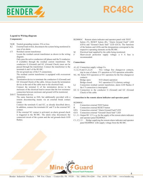
<strong>RC48C</strong>Legend to Wiring diagramComponents:NGRK2CTE6...Neutral grounding resistor, 25A or less.External load switch, disconnects the system being monitored incase of an alarm.Residual current transformer.Locate the residual current transformer as shown in the wiringdiagram.Only pass the active conductors (all phases and the N conductor,if available) through the residual current transformer. Theconductors G (Ground) and GC (Ground Check) must not bepassed through the transformer. Connect the transformer to theterminals k and l of the <strong>RC48C</strong>.Do not ground any of the CT connections.The residual current transformer is equipped with overcurrentprotection.Termination device to terminate the conductors G (Ground) andGC (Ground Check) of the cable. Always locate the terminationdevice at the end of the cable near to the electrical load.Connect the terminal G of the termination device to theenclosure of the electrical load to ensure that the low-resistanceconnection between enclosure and ground will be monitored.E6S-T Termination device.The same function as E6S, but additionally provided with aremote disconnecting means via an external break contact(stop).Connect the terminals G and GC, as already described above.In addition, connect the terminals GC and T to the external NCcontact.If the external NC contact is activated, an alarm ground checkis triggered in the <strong>RC48C</strong>. The alarm relay disconnects theconnected circuit of the system and the red ground-check LEDflashes.RI2000GC Remote alarm indicator and operator panel with TESTbutton (T), RESET button (R), “Alarm Ground Fault” LED(GFA) and “Ground Check Safe” LED (GCS). The functionsof the buttons and LEDs and the designations correspond to therespective operating elements on the <strong>RC48C</strong>.MFElectrical load supplied by the cable being monitored.Short-circuit protection supply voltage: a 6 A fuse isrecommended.Connections:A1,A2 Connection supply voltage Us.11,12,14 and 21,22,24 Two voltage free changeover contacts,trip in case of alarm. UV operation or N/O operation selectable.NC, NC Select N/O operation or N/C operation for the free changeovercontacts:Bridge open: N/O (shunt) operationk,lBridge closed: N/C operation (UV) (factory setting)Connection residual current transformer, alarm LED flashes ifthe CT connection is interruptedGC. G Connection to the conductor G (Ground) and GC (GroundCheck) of the cable.Connection to the remote alarm indicator and operator panelRI2000GC:T Connection external TEST buttonR Connection external RESET buttonGFA Connection external “Alarm Ground Fault”LEDGCS Connection external “Ground Check Safe” LEDU+, U- Output DC 12 V, e.g. for the supply of the remote alarm indicatorand operator panel RI2000GC.C1, C2, U+ Bridge supplying the remote alarm indicator and operatorpanel RI2000GC with supply voltage from the <strong>RC48C</strong>. <strong>Bender</strong> Industrial Products - 700 Fox Chase - Coatesville PA 19320 - Tel. (800)-356-4266 - Fax. (610) 383-7100 - www.bender.org4


