A-ISOMETER® IRDH375 IRDH375B - Bender
A-ISOMETER® IRDH375 IRDH375B - Bender
A-ISOMETER® IRDH375 IRDH375B - Bender
You also want an ePaper? Increase the reach of your titles
YUMPU automatically turns print PDFs into web optimized ePapers that Google loves.
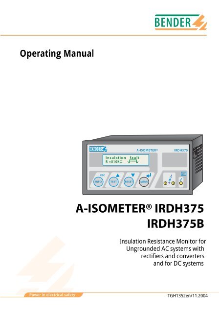
Operating ManualInsulationR =010KWfaultA-ISOMETER®<strong>IRDH375</strong>ESCkWINFO TEST RESET MENU1 2A-ISOMETER® <strong>IRDH375</strong><strong>IRDH375</strong>BInsulation Resistance Monitor forUngrounded AC systems withrectifiers and convertersand for DC systemsPower in electrical safetyTGH1352en/11.2004
<strong>Bender</strong> Inc.700 Fox ChaseCoatesville, PA 19320Tel.: 610-383-9200Fax: 610-383-7100E-Mail: info@bender.orgInternet: http://www.bender.org© 2004 BENDER GroupAll rights reserved.Reprinting only with permissionof the publisher.Subject to change
Table of Contents1. Safety information ............................................................................ 71.1 Use for the intended purpose ........................................................ 71.2 Warranty and liability ........................................................................ 71.2.1 Personnel ............................................................................................... 81.2.2 About the operating manual .......................................................... 81.2.3 Hazards when handling the A-ISOMETER® <strong>IRDH375</strong> ............. 81.2.4 Inspection, transport and storage ................................................ 91.2.5 Note ......................................................................................................... 91.3 Explanations of symbols and warnings ................................... 101.4 Directions for installation .............................................................. 112. Function ........................................................................................... 132.1 Common characteristics (<strong>IRDH375</strong> and <strong>IRDH375</strong>B) ............ 132.2 Additional characteristics <strong>IRDH375</strong>B ........................................ 132.3 Product description ........................................................................ 142.4 Function .............................................................................................. 142.5 Additional functions <strong>IRDH375</strong>B .................................................. 173. Commissioning flow chart (threepart) ....................................... 214. Connection ...................................................................................... 254.1 Wiring ................................................................................................... 254.2 Wiring diagrams with coupling devices .................................. 284.2.1 Connection with AGH150W-4 ..................................................... 284.2.2 Connection with AGH520S ........................................................... 294.2.3 Connection with AGH204S-4 ....................................................... 30TGH1352en/11.20043
Table of Contents5. Operation and setting .................................................................... 335.1 Operating features and displays <strong>IRDH375</strong>(B) ......................... 335.1.1 Display in the standard mode ...................................................... 345.1.2 Display in the menu mode ............................................................ 345.1.3 Function keys ..................................................................................... 355.2 Menu structure and menu mode ............................................... 385.2.1 Diagram menu structure ............................................................... 395.3 Menu HISTORY INFO (<strong>IRDH375</strong>B) ............................................... 405.3.1 Diagram HISTORY INFO (<strong>IRDH375</strong>B) .......................................... 415.4 Menu ISO SETUP:Setting of the basic A-ISOMETER® functions .......................... 425.4.1 Response values Alarm 1 and Alarm 2 ...................................... 425.4.2 Operating principle of the alarm relays ................................... 425.4.3 Memory setting (on/off) ................................................................ 445.4.4 Current output for external measuring instruments(<strong>IRDH375</strong>B) .......................................................................................... 445.5 Menu ISO ADVANCED:Setting of the extended functions ............................................. 455.5.1 External coupling devices (AGH: no) ......................................... 455.5.2 Adaptation to the system leakage capacitance(Cemax : 150 µF) ................................................................................ 465.5.3 Changing the measuring principle from AMP to DC(Measure: AMP) ................................................................................. 465.5.4 Setting the repetition time for automatic self tests(Autotest: 24h) ................................................................................... 465.5.5 Setting the real-time clock (Clock) (<strong>IRDH375</strong>B) ..................... 465.5.6 Setting the date (Date) (<strong>IRDH375</strong>B) ........................................... 465.5.7 Specifying the starting time of the automatic self test(Test) (<strong>IRDH375</strong>B) .............................................................................. 465.5.8 Diagram ISO ADVANCED ............................................................... 475.6 Menu COM SETUP:Setting the BMS interface .............................................................. 484 TGH1352en/11.2004
Table of Contents5.6.1 Bus address „Addr:“ (<strong>IRDH375</strong>B) ................................................ 485.6.2 ISOnet function (<strong>IRDH375</strong>B) ......................................................... 485.6.3 ISO monitor (<strong>IRDH375</strong>B) ................................................................ 485.6.4 Diagram COM SETUP (<strong>IRDH375</strong>B) .............................................. 495.7 Menu PASSWORD ............................................................................ 505.7.1 Activating and setting the password ........................................ 505.7.2 Diagram PASSWORD ...................................................................... 505.8 Menu LANGUAGE ........................................................................... 515.8.1 Setting the national language .................................................... 515.8.2 Diagram Language .......................................................................... 515.9 Menu SERVICE ................................................................................... 525.10 Parameterization via Internet ...................................................... 526. Serial interfaces .............................................................................. 536.1 RS485 interface with IsoData protocol (<strong>IRDH375</strong>) ............... 536.2 RS485 interface with BMS protocol (<strong>IRDH375</strong>B) ................... 556.3 Topology RS485 network (<strong>IRDH375</strong>B) ...................................... 566.3.1 Correct arrangement ...................................................................... 566.3.2 Wrong arrangement ....................................................................... 566.3.3 Wiring ................................................................................................... 566.4 BMS protocol (<strong>IRDH375</strong>B) ............................................................. 576.4.1 BMS Master ........................................................................................ 576.4.2 BMS Slave ............................................................................................ 586.4.3 Commissioning of an RS485 network with BMS protocol 597. Technical data <strong>IRDH375</strong>(B) ........................................................... 617.1 Data in tabular form ........................................................................ 617.2 Standards and approvals .............................................................. 647.3 Characteristic curves ....................................................................... 657.4 Ordering details ................................................................................ 72TGH1352en/11.20045
Table of Contents7.4.1 A-ISOMETER® ..................................................................................... 727.4.2 Dust protection ................................................................................. 727.4.3 Coupling devices .............................................................................. 737.4.4 Measuring instruments .................................................................. 737.4.5 Label for modified versions .......................................................... 736 TGH1352en/11.2004
1. Safety information1.1 Use for the intended purposeThe A-ISOMETER® is intended for:• monitoring the insulation resistance of ungrounded ("IT") systemsAny other use, or any use which goes beyond the foregoing, is deemed tobe use other than for the intended purpose. The BENDER companies shallnot be liable for any losses or damage arising therefrom.Use for the intended purpose also includes• compliance with all information in the operating instructions, and• compliance with test intervals.As a basic priciple, our "General conditions of Sale and Delivery" shall apply.At the latest, these shall be available to the operator when the contract is concluded.1.2 Warranty and liabilityWarranty and liability claims in cases of damage to persons and propertyshall be excluded if they are attributable to one or more of the followingcauses:• Use of the A-ISOMETER® other than for the intended purpose• Incorrect assembly or installation, commissioning, operation and maintenanceof the A-ISOMETER®.• Failure to comply with the information in the operating instructions regardingtransport, commissioning, operation and maintenance of the A-ISOMETER®.• Unauthorized structural modifications to the A-ISOMETER®.• Failure to comply with the technical data• Improperly executed repairs, and the use spare parts or accessories which arenot recommended by the manufacturer.• Cases of disaster and force majeure• Assembly and installation with device combinations not recommended.TGH1352en/11.20047
Safety informationThis operating manual, especially the safety information, must be observedabove all by personnel who work on the A-ISOMETER®.In addition, the rules and regulations that apply for accident prevention atthe place of use must be observed.1.2.1 PersonnelOnly appropriately qualified staff may work on the A-ISOMETER®. Qualifiedmeans familiar with the installation, commissioning and operation of theproduct and with training appropriate to the work.Personnel must have read and understood the safety section and warning informationin this operating manual.1.2.2 About the operating manualThis operating manual has been compiled with the greatest possible care.Nevertheless, errors and mistakes cannot be entirely ruled out. The BENDERcompanies assume no liability whatsoever for any injury to persons or damageto property which may be sustained as a result of faults or errors in thisoperating manual.1.2.3 Hazards when handling the A-ISOMETER® <strong>IRDH375</strong>The A-ISOMETER® <strong>IRDH375</strong> is constructed according to the state-of-the-artand recognized technical safety rules. Nevertheless, when it is being used,hazards may occur to the life and limb of the user or third parties, or theremay be adverse effects on the A-ISOMETER® or on other valuable property.The A-ISOMETER® must only be used:• for the purpose for which it is intended• when it is in perfect technical condition as far as safety is concernedAny faults which may impair safety must be eliminated immediately. Impermissiblemodifications and the use of spare parts and additional deviceswhich are not sold or recommended by the manufacturer of the devices maycause fires, electric shocks and injuries.Unauthorized persons must not have access to or contact with theA-ISOMETER®. Warning signs must always be easily legible. Damaged or illegiblesigns must be replaced immediately.8 TGH1352en/11.2004
Safety information1.2.4 Inspection, transport and storageInspect the dispatch packaging and equipment packaging for damage, andcompare the contents of the package with the delivery documents. In theevent of damage in transit, please inform the BENDER company immediately.The devices must only be stored in areas protected from dust, damp andspray or dripping water, and in which the specified storage temperatures aremaintained.1.2.5 NoteMake sure that the operating voltage is correct!Prior to insulation and voltage tests, the A-ISOMETER® must be disconnectedfrom the power system for the duration of these tests.In order to check the proper connection of the device, it is recommended tocarry out a functional test.Make sure that the basic settings meet the requirements of the system.Children and unauthorized persons must not have access to or contact withthe A-ISOMETER®.TGH1352en/11.20049
Safety information1.3 Explanations of symbols and warningsThe following symbols are used in BENDER documentation to draw attentionto important information and to make it easier to find certain text passages.The following examples explain the meaning of the symbols:The "Attention" symbol is used to draw attention to informationwarning employees of hazardous situations.Information you should know for correct handling of the product ismarked with the "Info" symbol.10 TGH1352en/11.2004
Safety information1.4 Directions for installationOnly one insulation monitoring device may be used in each interconnectedungrounded (IT) system.When insulation or voltage test are to be carried out, the device shallbe isolated from the system for the test period.The terminals and KE shall be connected by a separate wire to the protectiveconductor (PE). If the terminals L1, L2 of the device are connected toa system under operation, the terminals and KE must not be disconnectedfrom the protective conductor (PE).In order to check the proper connection of the device, it is recommended tocarry out a functional test using a genuine earth fault, e.g. via a suitable resistance,before starting the A-ISOMETER®.The devices, variant -4.. are delivered with the following factory setting:ISO SETUP: Alarm 1 / Alarm 2 =40 kΩ / 10 kΩ(response values)ISO SETUP:Operating principle K1/K2 = N/O operationISO SETUP:Memory = offISO ADVANCED: System leakage capacitance = 150 µFCOM SETUP:Bus address = 3 (slave)Please check if the basic setting of the A-ISOMETER® complies with the requirementsof the system to be monitored.When an AC system includes galvanically connected DC circuits, thefollowing shall be considered:Insulation faults in DC circuits can only be monitored correctly whenthe rectifiers carry a continuous load of 5...10 mA.TGH1352en/11.200411
Safety information12 TGH1352en/11.2004
2. Function2.1 Common characteristics (<strong>IRDH375</strong> and <strong>IRDH375</strong>B)• A-ISOMETER® for ungrounded AC systems with galvanically connected rectifiersand for ungrounded DC systems ("IT-systems" = ungrounded / floating systems)• The operating range of the nominal voltage U n can be extended via couplingdevices.• Automatic adaptation to the existing system leakage capacitance• measuring principle (European Patent: EP 0 654 673 B1)• Two separately adjustable ranges of the response value1 kΩ ...10 MΩ(Alarm 1, Alarm 2)• Two-line LC display• Connection monitoring (monitoring of the measuring leads)• Automatic device self test• Option "W":This option provides: improved shock and vibration resistance for use in ships,on rolling stock and in seismic environment.2.2 Additional characteristics <strong>IRDH375</strong>B• Memory with real-time clock to store all alarm messages with date and timestamp.• BMS interface (BMS protocol) for data exchange with other <strong>Bender</strong> devices(RS485 electrically isolated).• Internal disconnection of the A-ISOMETER from the IT system to be monitored(using a control signal; terminals F1/F2) , e.g. if several A-ISOMETERs® are interconnected.• Current output 0(4)...20mA (galvanically separated) in relation to the measuredinsulation value.• Remote setting of certain parameters via the Internet (option; FTC470XETadditionally required)TGH1352en/11.200413
Function2.3 Product descriptionThe A-ISOMETER® type <strong>IRDH375</strong> monitors the insulation resistance of ITsystems. It is suitable for universal use in 3(N)AC, AC/DC and DC systems.AC systems may include extensive DC supplied loads, such as converters orthyristor-controlled DC drives. The device automatically adapts itself to theexisting system leakage capacitance.Suitable coupling devices are available to extend the nominal voltage rangeU n .The <strong>IRDH375</strong>B can be used in combination with a control and indicating device,e.g. PRC1470 version 2 or higher, on the BMS (BMS = <strong>Bender</strong> MeasuringDevice Interface) bus.2.4 FunctionThe A-ISOMETER® <strong>IRDH375</strong> is connected between the unearthed system (ITsystem) and the protective conductor (PE).The response values and other function parameters are set via the functionkeys. The parameters are indicated on the LC display and are stored in a nonvolatilememory (EEPROM) after the setting is completed.A microprocessor-controlled pulsating AC measuring voltage is superimposedon the IT system to be monitored ( measuring principle*). Themeasuring cycle consists of positive and negative pulses of the same amplitude.The period of these pulses depends on the respective system leakagecapacitances and the insulation resistances of the IT system to be monitored.An insulation fault between the IT system and earth closes the measuring circuit.From the measured current value, the microprocessor calculates the insulationresistance which is indicated on the LC display or the external kOhmmeasuring instrument.The measuring time is determined by the system leakage capacitances, theinsulation resistance, and the system-related interference disturbances. Systemleakage capacitances do not influence the measuring accuracy.If the reading is below the selected response values Alarm 1/Alarm 2, the associatedalarm relays respond and the alarm LEDs "Alarm 1/2“ light up andthe measuring value is indicated on the LC display (in the event of DC insulationfaults, the faulty supply line is indicated). If the terminals R1/R2 arebridged (external RESET button [NC contact] or wire bridge), the fault indicationwill be stored. Pressing the RESET button, resets the insulation fault14 TGH1352en/11.2004
Functionmessage, provided that the currently displayed insulation resistance is atleast 25% above the actual response value when the reset is carried out. Thefault memory behaviour can also be set in the "ISO SETUP" menu, by selectingthe sub menu Memory: on/off.The connections for external kΩ display supplied by the current output0 ... 400 µA or 0(4)...20 mA (<strong>IRDH375</strong>B) at M+/M- are galvanically isolated.*) measuring principle "adaptive measuring pulse", a measuringprinciple developed by BENDER (European Patent: EP 0 654 673 B1).Self testA self test can be carried out manually using the TEST button or automatically.In order to guarantee high functional reliability, the A-ISOMETER®<strong>IRDH375</strong> provides comprehensive self test functions. After switching thesupply voltage on, all internal measuring functions, the components of theprocess control such as data and parameter memory as well as system andearth connections are checked using the self test functions. The progress ofthe self test is indicated on the display by a bar graph. Depending on theconditions in the IT system to be monitored, the self test is running for15...20 seconds, then the message "Test ok!“ appears on the LC display forapproximately 2 seconds. Then the device returns to normal measuringmode and the current measuring value is displayed after the expiry of themeasuring time.When a device or connection fault is found, the message "!Error!" appears onthe display, the system fault LED lights up, the relay K3 (31-32-34) switchesand the respective fault message (see table) is indicated. If such a systemfault occurs, a self test is started again every minute. If no more malfunctionis detected, the fault message is deleted automatically and the system faultLED extinguishes.During operation, the self test function can be started by pressing the TESTbutton (internal or external). The self test can also be started automaticallyevery hour or every 24 hours by selecting "ISO ADVANCED: Autotest" menu.The alarm relays Alarm1/2 only switch after starting the self test function bypressing the TEST button, that means if an automatic self test has been selected,the alarm relays do not switch.TGH1352en/11.200415
FunctionError message Meaning Steps to be takenSystem connection?Connection PE?Device error xNo low-resistanceconnection of terminalsL1, L2 tothe IT systemNo low-resistanceconnection of theterminals andKE to earth (PE)Internal deviceerror1. Check the wiring of terminal L1, L2 tothe IT system2. Press the test button3. Switch the supply voltage off and on.4. Check the fuses1. Check wiring of terminal and KE toearth (PE)2. Press TEST button3. Switch the supply voltage off and on1. Press TEST button2. Switch the supply voltage off and on3. Contact BENDERIf the on/off switching of the supply voltage is not possible for technicalreasons, a RESET of the process control can be carried out by pressingthe "ESC“, "RESET“ and "MENU“ key.16 TGH1352en/11.2004
Function2.5 Additional functions <strong>IRDH375</strong>BCurrent output for external measuring instrumentThe current output of <strong>IRDH375</strong>B provides 0(4)...20 mA. The current outputis galvanically isolated from the device electronics and the RS485 interface.The ISO SETUP menu, on page 43, allows to switch over between 0...20 mAand 4...20 mA.Real-time clockThe real-time clock serves as a time base for the memory and self test functions.At first, the correct time and date must be set in the menu "ISO AD-VANCED". If time and date are not set, a „C“ (clock) is flashing in thestandard display. In the event of a supply voltage failure, time and date willbe stored for at least thirty days.If the 24 h selv test is activated in the "ISO ADVANCED" menu, a special timeof day can be selected for the execution of the self test in the menu "TEST:12:00". Then a self test will be started automatically once a day exactly at thepreset time. If the 1 h auto test has been selected, the self test is automaticallycarried out every full hour.Interconnected IT systemsWhen using A-ISOMETERs® in IT systems, make sure that only one activeA-ISOMETER® is connected in each interconnected system. If IT systems areinterconnected via coupling switches, make sure that A-ISOMETERs® notcurrently used are disconnected and deactivated via a control system. IT systemscoupled via diodes or capacitances may also influence the insulationmonitoring process. Hence, also in this case a central control of the differentA-ISOMETERs® is required.Function input F1/F2 for connection or disconnection ofIT systems being monitoredThe A-ISOMETER® can be disconnected from the IT system and set toSTANDBY mode with the function input F1/F2. If the input F1/F2 is bridged,the connections L1/L2 are switched off via internal coupling relays, the measuringfunction is stopped and the message "STANDBY" appears on the display.Software version 1.4 or higher does not indicate the measuredinsulation resistance during the disconnection, but indicates the value> 10 MΩ. Furthermore, the alarm relays and alarm LEDs no longer providealarm messages. After opening the function input F1/F2, the connection tothe IT system will be restored and a completely new measuring cycle for in-TGH1352en/11.200417
Functionsulation monitoring is started.With this function, selective disconnection of an <strong>IRDH375</strong> in interconnectedIT systems can be carried out via auxiliary contacts of the respective couplingswitch. One coupling switch each in a line-type or ring-type arrangement candeactivate a subsequent <strong>IRDH375</strong>. This arrangement guarantees that onlyone A-ISOMETER® is active in each galvanically connected system. In a ringtypearrangement with all coupling switches closed, it can be assumed thatall A-ISOMETERs® are deactivated. In order to prevent this, a BMS Master(<strong>IRDH375</strong>B BMS address 1) monitors the condition of the function input F1/F2 of all slave A-ISOMETERs®. When all slave A-ISOMETERs® are in theSTANDBY mode, the insulation monitoring function of the MasterA-ISOMETER® and hence the function input F1/F2 of the Master are withoutfunction in this mode.Details are shown in the graphic below.BMS bus (A/B, RS485)F1/F2<strong>IRDH375</strong>BAddr. 1 Addr. 2F1/F2 <strong>IRDH375</strong>BPEPEGIT system 1 IT system 2GGIT system 4IT system 3G<strong>IRDH375</strong>BPEAddr. 4 Addr. 3<strong>IRDH375</strong>BF1/F2 F1/F2PE18 TGH1352en/11.2004
FunctionISOnet Function (COM SETUP)Select "ISOnet=ON" from the COM SETUP menu to activate this function.This function is a type of scanning function. The BMS Master activated viathe ISOnet function controls the ISOnet slave devices via the BMS bus. Oncean A-ISOMETER® has finished its measurement cycle, the authorization formeasuring the insulation resistance is passed on from the ISOnet Master tothe next slave. While an A-ISOMETER® is carrying out a measurement allother A-ISOMETERs® are in the STANDBY mode. In this way it can be preventedthat the A-ISOMETERs® disturb each other in interconnected systems.In comparison to the solution coupling switches and function input F1/F2, the response time is prolonged, since no continuous measurement takesplace. The advantage is that no auxiliary contacts of a coupling switch arerequired. Furthermore, this solution is ideally suited for capacitive IT systemsor IT systems connected via diodes.An ISOnet slave checks whether there is a Master available in the network.If there is no Master available, the fault message "ISOnet Master?" appears onthe display. When the ISOnet function is activated, the function input F1/F2will be disconnected.BMS bus (A/B, RS485)<strong>IRDH375</strong>BAddr. 1 Addr. 2<strong>IRDH375</strong>BPEPEGIT system 1 IT system 2GGIT system 4IT system 3G<strong>IRDH375</strong>BAddr. 4 Addr. 3<strong>IRDH375</strong>BPEPETGH1352en/11.200419
Function20 TGH1352en/11.2004
3. Commissioning flow chart (threepart)Due to limitations of space, the three-part flow chart begins on the next page.TGH1352en/11.200421
Commissioning flow chart (threepart)The encircled figures in the flow chart correspond to the figures in the legendto the wiring diagram.Commissioning of the A-ISOMETER® (1)noIs the system to be monitored anunearthed system (IT system)?The <strong>IRDH375</strong> is not suitable for thisapplication( contact BENDER).Is the maximum nominal voltageUn AC 793 VorUn DC 650 VnoUn is too high for directconnection. A coupling deviceproviding the respective voltagerange must be connected.Deenergize the installationbefore connecting the device!yesDevice connectionRecommended wire cross section ofconnecting cablesingle wire 0.2...4 mm2flexible 0.2... 2.5 mm2yesOptional deviceconnectionThe two PE connections and KE mustbe connected separately to theequipotential bonding.The terminals L1 and L2 must beconnected to Un of the system to bemonitored according to the wiring diagram.Connect the supply voltage Usto the terminals A1/+ and A2/-. Considerthe details indicated on the nameplate.623451An external kW measuring instrumentat M+/M- with a display range of10 kW...1000 kW,Scale centre point: 120 kWOutput current <strong>IRDH375</strong>: 0...400 mAOutput current <strong>IRDH375</strong>B: 0/4...20 mAExternal TEST button (NO contact) to theterminals T1 and T2External RESET button (NC contact) to theterminals R1 and R2When using the RS485 interface, take carethat a 120 W resistor is connected at 11the beginning and the end of the network.Terminate IRDH...: S1 = ONThe output contacts of the alarm relaysSystem fault (31-32-34)Alarm 1 (11-12-14)Alarm 2 (21-22-24)22 TGH1352en/11.2004
Commissioning flow chart (threepart)Commissioning of the A-ISOMETER® (2)Connect the supplyvoltage USConnect the voltage Un of theIT system to be monitoredThe A-ISOMETER carries out aself test. The display indicatesthe insulation value after finishingthe measurement.Only <strong>IRDH375</strong>B:set the clockShall the basic settingbe changed?Alarm1 = 40 kWAlarm2 = 10 kWK1/K2 = N/O operationMemory = offnoyesSelect ISO SETUP(see chapter operation and setting)Does one of the alarm LEDslight up?noyesThe insulation value of the systembeing monitored is below the presetresponse value. Change the responsevalue or improve the insulationcondition of the system.TGH1352en/11.200423
Commissioning flow chart (threepart)Commissioning of the A-ISOMETER® (3)In order to check the properconnection, a functional testusing a suitable resistance isto be carried out.Size of the resistance:50% of the preset responsevalue Alarm 2.Do both alarm LEDs light up?Did the alarm relays switch ?yesnoCheck the connecting leads !Is voltage Un applied to theterminals L1/L2 ?When a coupling device isused, is it correctly connected ?Check the voltages with a voltmeteDo both alarm LEDs light ?Did the alarm relays switch?Remove the resistor !yesAlarm LEDs extinguished ?Did the output relays changetheir position ?noyesThe <strong>IRDH375</strong> is correctlyconnected and functions reliably !24 TGH1352en/11.2004
4. Connection4.1 Wiring<strong>IRDH375</strong>(B) has plug-in terminals.Connect the terminals A1/+ and A2/- to the supply voltage U S in accordancewith IEC 60364-4-43. The connections to the supply voltage shall be providedwith protective devices to afford protection in the event of a short circuit(a 6 A fuse is recommended).Devices for protection against short-circuit in conformity withIEC 60364-4-43 for the IT system coupling L1/L2 can be omitted if the wiringis carried out in such a manner as to reduce the risk of a short-circuit to aminimum (a short-circuit-proof and earth-fault-proof wiring is recommended).Only one A-ISOMETER® may be connected to an external TEST or RESETbutton. The TEST and RESET button for collective testing of several insulationmonitoring devices must not be connected in parallel.External coupling devices connected via the terminal AK cannot be switchedoff via the internal coupling relays. If no coupling device is used, the terminalAK remains free.TGH1352en/11.200425
Connection1234mA567 89RS485ONM+ M- T1 T2 R1 R2 F1 F2 A B 31 32 34 21 22 24 11 12 14OFFS2 S1<strong>IRDH375</strong>K3 K2 K1A1/+ A2/- L1 L2 AK KE106 A3 (N)AC-SystemUnL1L2L1L2L31115PE163 AC-SystemUnL1L2NL+L1L2L312AC-SystemUnL1L2L1L213L1L2DC - SystemUnL-1426 TGH1352en/11.2004
ConnectionLegend to wiring diagram:1 For external indicating instrument:<strong>IRDH375</strong>: current output, not galvanically separated: 0 ... 400 µA<strong>IRDH375</strong>B: current output, galvanically separated: 0...20 mA or 4...20 mA2 External TEST button (NO contact)3 External RESET button (NC contact or wire jumper),when the terminals are open, the fault message will not be stored4 STANDBY by means of the function input F1, F2:When the contact is closed, insulation measurement does not take place;system disconnection5 S1 = ON: RS485 interface (A/B) is terminated with 120 Ω resistorS2 = unassigned6 Serial interface RS485 (A/B)7 System fault relay K3; changeover contacts provided8 Alarm relay K2; changeover contacts provided9 Alarm relay K1; changeover contacts provided10 Supply voltage U s (see nameplate) via 6 A fuse11 Connection to the 3/N AC system to be monitored:connect terminals L1, L2 to neutral conductor N12 Connection to the 3 AC system to be monitored:connect terminals L1, L2 to conductor L1, L213 Connection to the AC system to be monitored:connect terminals L1, L2 to conductor L1, L214 Connection to the DC system to be monitored:connect terminal L1 to conductor L+, terminal L2 to conductor L-15 Connection for external coupling devices (Extension of the nominal voltagerange U n )16 Separate connection of and KE to PETGH1352en/11.200427
Connection4.2 Wiring diagrams with coupling devicesPlease observe the settings in the "ISO ADVANCED AGH“ menu ! Adaptthe settings to the coupling device to be used.4.2.1 Connection with AGH150W-4Connected to the A-ISOMETER® this coupling device extends the nominalvoltage range to DC 1760 V in DC systems.AK160AGH150W-4AK<strong>IRDH375</strong>KEAchtung HochspannungDanger High Voltage+ -UnDC 0 ... 1760 VL+L-PE28 TGH1352en/11.2004
Connection4.2.2 Connection with AGH520SConnected to the A-ISOMETER® this coupling device extends the nominalvoltage range to AC 7200 V in pure AC systems. In case of 3 AC systems, Pin2 of AGH520S is to be connected to L1, in case of 3/N AC systems, Pin 2 isto be connected to the N-conductor.Un3/(N) AC 0...7200 V42...460 HzL1L2L3N3/N/ AC3 AC2AGH520S5 4 3<strong>IRDH375</strong>AKKEPETGH1352en/11.200429
Connection4.2.3 Connection with AGH204S-4This coupling device extends the nominal voltage range of A-ISOMETERs®used in AC systems including rectifiers.12AK<strong>IRDH375</strong>KEAK160 AK80AGH204S-4U3 V3 W3UnL1L2L3NPE1 without rectifiers U n = 3AC 0....1650 V (DC max. 1000 V)2 with rectifiers U n = 3AC 0....1300 V (max. AC voltage; max. DC voltageafter rectifiers in intermediate circuits of frequency converters:1840V)The maximum DC voltage is the voltage permitted to occur in the AC part ofan IT system to PE when the <strong>IRDH375</strong> is coupled with AGH204S-4 in thispart of the system. This voltage is dependent on the level of the nominal voltage,the type of rectification 6 pulse, 12 pulse,...), the type of converter intermediatecircuit (current... or voltage...), and the converter technology. Incase of converters, the maximum DC voltage in the intermediate circuit usuallycorresponds to the phase-to-phase voltage of the supplying AC systemmultiplied by 1.414.30 TGH1352en/11.2004
ConnectionIn case of current-controlled intermediate circuits of frequency converters,higher DC voltages are to be expected.The given voltage values for AC/DC systems take into account values foundby previous experience (factor 1.414 between DC voltage and AC voltage).The maximum DC voltage in case of insulation faults in the DC part of theIT system, for example converter intermediate circuit, is DC 1840 V. Fromthis, the maximum nominal AC voltage is calculated:U max = DC 1840 V / 1.414 = AC 1300 VTGH1352en/11.200431
Connection32 TGH1352en/11.2004
5. Operation and setting5.1 Operating features and displays <strong>IRDH375</strong>(B)A-ISOMETER®<strong>IRDH375</strong>InsulationR =010KWfault8ESCkWINFO TEST RESET MENU1 21 2 3 4 5 6 71 INFO key: to query standard information /ESC key: back (menu function), confirmation parameter change2 TEST button: to call up the self test/Up key: parameter change, moving up in the menu3 RESET button: to delete insulation fault alarmsDown key: parameter change, moving down in the menu4 MENU key: to activate the menu system /Enter key: confirmation parameter change5 Alarm LED 1 lights: insulation fault, first warning level reached6 Alarm LED 2 lights: insulation fault, second warning level reached7 System fault LED lights: <strong>IRDH375</strong> defective8 Two-line display for standard and menu modeA detailed description of the operating elements is given on the followingpages.TGH1352en/11.200433
Operation and setting5.1.1 Display in the standard mode12InsulationRs=011kWFault. H431 Indication of the insulation resistance in kΩ2 Additional information about the insulationresistance:"+" = insulation fault at L+"–" = insulation fault at L–"s" = new measurement has started3 = polarity of the measuring pulse. = valid bus communication signalsH = new entry in the memory data baseC = flashing, clock is to be set4 Messages:- Insulation fault- Connection system?- Connection PE?- Device error x- *****STAND BY*****5.1.2 Display in the menu mode1. EXIT2. HISTORY INFOParameter change is permittedParameter change is blocked,enabling by a password34 TGH1352en/11.2004
Operation and setting5.1.3 Function keysTwo functions are assigned to each function key. In addition to the basicfunction marked with a circle, all the keys allow navigation within the menu.Pressing the INFO key provides the following informationESC without opening the menu:INFO• Device name, firmware version• Response values Alarm 1 and Alarm 2• Leakage capacitance C e (only indication if insulationresistances > 20 kΩ)• Setup status (for details refer to the table of the statusnumbers on page 70)• COM-Setup (<strong>IRDH375</strong> bus address)Please have the details above on hand if you have a problem and if you contactBENDER for technical questions.Activating the TEST button starts theA-ISOMETER® self test.TEST RESETPressing the RESET button resets insulation faultalarm messages stored in the A-ISOMETER®. Thememory function is only available after activating the fault memory in theISO SETUP menu or after bridging the terminals R1/R2. Furthermore, the A-ISOMETER® can only be reset when the present insulation value is 25 %higher than the set response value.The menu system is called up by pressing the MENU key.MENUTGH1352en/11.200435
Operation and settingFor controlling the menu system, the arrow keys, the ENTER key and the ESCkey are used:TESTUp key:Moving up in the menu, increasing a parameterRESETDown key:Moving down in the menu, reducing a parameterMENUINFOESCENTER keySelecting a menu item or sub menu item, confirming or storing aparameter change and going back to the associated sub menuitem or going to the next input area.ESC key:Returning from a sub menu to the previous menu.If you do not quit the menu, the device automatically returns tothe standard mode again after approximately five minutes.For the sake of clarity, the following symbols are used for the functionsENTER, UP/DOWN and ESCAPE in the menu diagrams of this operating manual:ESC36 TGH1352en/11.2004
Operation and settingTGH1352en/11.200437
Operation and setting5.2 Menu structure and menu modeSwitchover to the menu modeAfter pressing the MENU key, you can change from the standard mode to themenu mode. From the menu mode you can link to the different sub menus.Navigation within the menuSelect the desired menu item using the UP/DOWN keys. The selected menuitem is indicated by a flashing cursor. Press the ENTER key to open the associatedsub menu.Use the UP/DOWN keys again to select the desired parameters. Move thecursor to the edit field by pressing the ENTER key.If you have reached the end of the main menu list, it will be indicated by the"Arrow UP" symbol.Changing the parametersWhen password protection is activated, indicated by the symbol "padlockclosed" , the first thing to enter is the correct password before the parameterscan be changed using the UP/DOWN keys. Entering the correctpassword once allows all parameters to be changed as long as you do notleave the menu.Changing the parameter usually has an immediate effect on the measuringand alarm functions. The changed parameter is stored in a volatile memoryby pressing the ENTER or ESC key after returning to the sub menu (flashingcursor in column 1). During menu operations, all measuring and alarm functionscarry on working as usual in the background.Changing from the menu mode to the standard modePressing the ESC key allows fast changing from the menu mode to the standardmode. Thus, the menu item "EXIT" need not to be activated. Automaticswitchover from the menu mode to the standard mode takes place when nokey is pressed for approximately 5 minutes in a main or sub menu.38 TGH1352en/11.2004
Operation and setting5.2.1 Diagram menu structure*** IT-SYSTEM ***R >010 MWHMENUESC1. EXIT2. HISTORY INFO3. ISO SETUP4. ISO ADVANCED5. COM SETUP6. PASSWORD7. LANGUAGE8. SERVICEESCHISTORY INFOISO SETUP ISO ADVANCED COM SETUP PASSWORD LANGUAGE SERVICENr.: 01 #Nr.: 02Power on1. Exit2. AGH : no3. Ce max: 150 µF4. Measure: AMP5. Autotest: 24h6. Clock: 19:087. Date: 01.01.018. Test: 00:001. Exit2. Password: XXX3. Status: offInsert ServicePassword: XXX1. Exit2. Alarm1 040 kW3. Alarm2 010 kW4. K1 : N.O5. K2 : N.O6. Memory: on7. M+/M-: 0-20 mA1. Exit2. Addr: 0033. ISONet: off4. ISO Monitor1. Exit2. Text: Deutsch<strong>IRDH375</strong>B<strong>IRDH375</strong>TGH1352en/11.200439
Operation and setting5.3 Menu HISTORY INFO (<strong>IRDH375</strong>B)99 events with date and time stamp can be stored in the memory database.The database is designed as a ring memory, i.e. the eldest entry is overwritten.Data is written into a non-volatile memory and therefore provides protectionagainst voltage failure.Data record EventDisplay indication1 Switch the supply voltage on Power On2 Lowest measured insulation value Rmin3...99 Response value Alarm 1 released Alarm13...99 Response value Alarm 1 cleared Alarm13...99 Response value Alarm 2 released Alarm23...99 Response value Alarm 2 cleared Alarm23...99 Error system connection released System connection?3...99 Error system connection cleared System connection?3...99 Error PE connection released PE connection?3...99 Error PE connection cleared PE connection?3...99 Device error released Device error3...99 Device error cleared Device error3...99 System reset (watchdog) System resetBefore storing the events with the actual date and time stamp, set thereal-time clock in the ISO ADVANCED menu (refer to page 47).The following function keys are provided to query data from the "HISTORYINFO" menu: the UP/DOWN keys to change the data record number, the EN-TER key to change from the data record number to the menu item "Clearall:on" to delete the memory storage, and the ESC key to leave the menu.A new entry into the memory is signalled with an "H" on the display in thestandard mode. The "H" will be deleted as soon as the "HISTORY INFO"menu is called up.40 TGH1352en/11.2004
Operation and setting5.3.1 Diagram HISTORY INFO (<strong>IRDH375</strong>B)*** IT-SYSTEM ***R >010 MWH1. EXIT2. HISTORY INFO3. ISO SETUP4. ISO ADVANCED5. COM SETUP6. PASSWORD7. LANGUAGE8. SERVICEESCNr.: 01 #Nr: 08Power onNr.: 01 #Nr: 08Clear all: offNr.: 01 #Nr: 0828.08.01 17:43Nr.: 02 #Nr: 08Clear all: offNr.: 02 #Nr: 08Rmin: 010kNr.: 02 #Nr: 08Clear all: offNr.: 02 #Nr: 0825.08.01 10:13Nr.: 02 #Nr: 08Clear all: off<strong>IRDH375</strong>B<strong>IRDH375</strong>TGH1352en/11.200441
Operation and setting5.4 Menu ISO SETUP: Setting of the basic A-ISOMETER® functionsAll alarm functions such as Alarm 1 and Alarm 2 (prewarning and mainalarm), the operating principle of the alarm relays K1 and K2 (N.O = N/Ooperation, N.C = N/C operation), the fault storage behaviour and a selectionof two current output ranges are set in this menu.5.4.1 Response values Alarm 1 and Alarm 2The response values Alarm 1 and Alarm 2 are selected with the UP/DOWNkeys and stored with the ENTER key.5.4.2 Operating principle of the alarm relaysK1/K2 are factory set to N.O Test, that means N/O operation. When the supplement"Test" has been selected, the alarm relays switch over during a manualself test.If, for any reason, the alarm relays may not switch over during a manual selftest, the settings N.C or N.O are to be selected.K1: N.C Test = N/C operation contacts 11-12-14, with relay test(the alarm relay is energized during normal operation)K1: N.O Test = N/O operation contacts 11-12-14, with relay test(the alarm relay is deenergized during normal operation)K1: N.C = N/C operation contacts 11-12-14, without relay test(the alarm relay is energized during normal operation)K1: N.O = N/O operation contacts 11-12-14, without relay test(the alarm relay is deenergized during normal operation)K1: Flash = Flashing function contacts 11-12-14(the alarm relay and the LED flash in the event of an alarmmessage, approximately 0.5 HzK2: N.C Test = N/C operation contacts 21-22-24, with relay test(the alarm relay is energized during normal operation)K2: N.O Test = N/O operation contacts 21-22-24, with relay test(the alarm relay is deenergized during normal operation)K2 : N.C = N/C operation contacts 21-22-24, without relay testK2 : N.O(the alarm relay is energized during normal operation)= N/O operation contacts 21-22-24, without relay test(the alarm relay is deenergized during normal operation)K2 : Flash = Flashing function contacts 21-22-24(the alarm relay and the LED flash in the event of an alarmmessage, approximately 0.5 Hz)42 TGH1352en/11.2004
Operation and settingDiagram ISO SETUP*** IT-SYSTEM ***R >010 MWH1. EXIT2. HISTORY INFO3. ISO SETUP4. ISO ADVANCED5. COM SETUP6. PASSWORD7. LANGUAGE8. SERVICE1. Exit2. Alarm1: 100 KW3. Alarm2: 200 KW4. K1 : N.O5. K2 : N.O6. Memory: off7. M+/M-: 0-20 mAAlarm1 : 100 KWAlarm2 : 200 KWK2: N.OK1: N.OK1: N.O TestK1: N.C TestK1: FlashK1: N.OK1: N.CMemory: offMemory: onMemory: off<strong>IRDH375</strong>BM+/M-: 0-20 mAM+/M-: 0-20 mAM+/M-: 4-20 mA<strong>IRDH375</strong>TGH1352en/11.200443
Operation and settingDuring the automatic self test, the alarm relays are not switchedover.5.4.3 Memory setting (on/off)Memory: on = Fault memory is activatedThe device must be reset with the RESET button afterclearing the fault.Memory: off = Fault memory deactivated (factory setting)5.4.4 Current output for external measuring instruments (<strong>IRDH375</strong>B)Factory setting: 0...20 mAThe current output of the <strong>IRDH375</strong> can be set to "0...20 mA" oder "4...20 mA"via the menu point "M+/M-:". The maximum load is 500 Ω.Function 0...20 mA:R F = insulation fault, I= current in mAR F =20 mA x 120 kWI- 120 kWFunction 4...20 mA:R F = insulation fault, I= current in mAR F =16 mA x 120 kWI - 4 mA- 120 kWThe associated characteristic curves are illustrated on page 68.44 TGH1352en/11.2004
Operation and setting5.5 Menu ISO ADVANCED: Setting of the extended functions5.5.1 External coupling devices (AGH: no)Basic setting "no", when no coupling device is used (factory setting).AGH: 204 AK80Terminal AK of the <strong>IRDH375</strong> is connected to terminal AK80 of theAGH204S-4. The nominal voltage range is extended to 3AC 0...1650 V. Onlycurrent converters with an output voltage not exceeding DC 1000 V are allowedto be connected (see "operation with coupling device" on page 30).AGH: 520STerminal AK of the <strong>IRDH375</strong> is connected to terminal 5 of the AGH520S.The nominal voltage range is extended to AC 0...7200 V. Only current converterswith an output voltage not exceeding DC 1000 V are allowed to beconnected.AGH: 204 AK160Terminal AK of the <strong>IRDH375</strong> is connected to terminal AK160 of theAGH204S-4. The nominal voltage range is extended to 3AC 0...1300 V. Onlycurrent converters with an output voltage not exceeding DC 0...1840 V areallowed to be connected (see "operation with coupling device" on page 30).AGH: 150 AK160Terminal AK of the <strong>IRDH375</strong> is connected to terminal AK160 of theAGH150W-4. The nominal voltage range is extended to DC 0...1760 V.The coupling monitoring is deactivated when an external couplingdevice is connected.TGH1352en/11.200445
Operation and setting5.5.2 Adaptation to the system leakage capacitance (Cemax : 150 µF)This menu allows to adapt the A-ISOMETER® to the maximum system leakagecapacitance (max. 500 µF). Please note that the basic measuring time willbe increased to approximately 10 seconds when the setting is C e = 500 µF.Factory setting = 150 µF.5.5.3 Changing the measuring principle from AMP to DC (Measure: AMP)The DC measuring principle is only suitable for pure AC systems.Factory setting = AMP.5.5.4 Setting the repetition time for automatic self tests (Autotest: 24h)The time for the repetition of automatic self tests can either be set to 1 houror to 24 hours or can be deactivated.Factory setting = 24 h5.5.5 Setting the real-time clock (Clock) (<strong>IRDH375</strong>B)The setting of the real-time clock is the time base for the memory and for theautomatic self test. In case of failure of the supply voltage, the real-time clockkeeps running for approximately 30 days. When the device will be switchedon after this period, a flashing "C" appears on the display and the clock hasto be set again.5.5.6 Setting the date (Date) (<strong>IRDH375</strong>B)As well as the time, the date is required for the memory, too. In the event ofpower supply failure, the date function is not influenced for at least 30 days.If the device is switched on again after this period, a new setting of date andtime of the real-time clock is required.5.5.7 Specifying the starting time of the automatic self test (Test) (<strong>IRDH375</strong>B)If the 24h self test is activated in the ISO ADVANCED menu, it is possible toset the time (hour) when the self test is to be carried out by means of the"TEST: 12:00" sub menu. Then the self test is automatically carried out oncea day at a given time. If the 1 hour auto test has been selected, the self testwill be carried out at every full hour.46 TGH1352en/11.2004
Operation and setting5.5.8 Diagram ISO ADVANCED*** IT-SYSTEM ***R >010 MWH1. Exit2. AGH: no3. Ce max : 150µF4. Measure: AMP5. Autotest: 24h6. Clock: 21:097. Date: 01.01.018. Test: 12:001. EXIT2. HISTORY INFO3. ISO SETUP4. ISO ADVANCED5. COM SETUP6. PASSWORD7. LANGUAGE8. SERVICEAGH: noCe max : 150µFMeasure: AMPno150 AK160204 AK160520S204 AK80150µF500µFDCAMPAutotest: 24h24hno01hClock: 21:09Date: 01.01.01<strong>IRDH375</strong>BTest: 00:0000:00.23:00<strong>IRDH375</strong>TGH1352en/11.200447
Operation and setting5.6 Menu COM SETUP: Setting the BMS interface5.6.1 Bus address „Addr:“ (<strong>IRDH375</strong>B)This menu item is used to set the BMS bus address of the <strong>IRDH375</strong>. Sincethere are several A-ISOMETERs in one system, take care that the bus addressis not assigned twice.The device is factory set to address 3 and hence acts as a slave.If several <strong>IRDH375</strong> are operated on one BMS bus, the addresses of otherA-ISOMETERs must be assigned one after the other, since only one devicemay represent the Master.5.6.2 ISOnet function (<strong>IRDH375</strong>B)In the ISOnet = ON sub menu of the COM SETUP, the ISOnet function canbe set. The ISOnet function of all A-ISOMETERs existing in the system mustbe in "ON" position.A BMS Master with the ISOnet function activated, controls the ISOnet slavedevices via the BMS bus. If an A-ISOMETER® has completed the measuringcycle, the permission for insulation measurement is given from the ISOnetMaster to the next slave. During the measurement process carried out by anA-ISOMETER®, all other A-ISOMETERs® are in the STANDBY mode.5.6.3 ISO monitor (<strong>IRDH375</strong>B)This function allows to query the current measured value as well as the messagesof all bus-capable A-ISOMETERs existing in the BMS network. After selectingthe bus address, the entire information stored by the selected deviceis indicated on the display. The display indication is structured similar to thestandard indication, but instead of the indication of the measuring pulse, theselected bus address is indicated. Without pressing a key, the indicationchanges to the standard indication of the <strong>IRDH375</strong>B after about five minutes.If there is no information available from the selected A-ISOMETER®, themessage "!!!!NO DATA!!!!" will be displayed.Information is being searchedNo data foundCurrent data address 03R= K ADR:02!!!!NO DATA!!!!R= K ADR:02Insulation FaultR= 010K ADR:0348 TGH1352en/11.2004
Operation and setting5.6.4 Diagram COM SETUP (<strong>IRDH375</strong>B)*** IT-SYSTEM ***R >010 MWH1. EXIT2. HISTORY INFO3. ISO SETUP4. ISO ADVANCED5. COM SETUP6. PASSWORD7. LANGUAGE8. SERVICE1. Exit2. Addr: 0033. ISONet: off4. ISO MonitorAddr : 003ADR: 001..ADR: 030<strong>IRDH375</strong><strong>IRDH375</strong>BISONet : off! ! ! ! NO DATA ! ! ! !R= ADR: 01ADR: 01.ADR: 30ISONet : offISONet : onTGH1352en/11.200449
Operation and setting5.7 Menu PASSWORD5.7.1 Activating and setting the passwordThis menu can be used to activate a "Password" query. This protects the A-ISOMETER® against unauthorized settings and modifications. The desiredpassword (menu item 2. Password: xxx) can be set with the UP/DOWN keysand confirmed with the ENTER key. The password can be activated in themenu item "3. Status: on" by clicking the ENTER key. The basic setting is "3.Status: off", that means that the password is deactivated.5.7.2 Diagram PASSWORD*** IT-SYSTEM ***R >010 MWH1. EXIT2. HISTORY INFO3. ISO SETUP4. ISO ADVANCED5. COM SETUP6. PASSWORD7. LANGUAGE8. SERVICE1. Exit2. Password: XXX3. Status: offPassword: XXXPassword: XXXPassword: 000Password: . . .Password: 999Status: offStatus: offStatus: on50 TGH1352en/11.2004
Operation and setting5.8 Menu LANGUAGE5.8.1 Setting the national languageThe menu item "Language" allows fault messages of the A-ISOMETER® to beset to different languages. There is the choice of German and English.The device menu is not influenced by the language selection.5.8.2 Diagram Language*** IT-SYSTEM ***R >010 MWH1. EXIT2. HISTORY INFO3. ISO SETUP4. ISO ADVANCED5. COM SETUP6. PASSWORD7. LANGUAGE8. SERVICE1. Exit2. Text: Deutsch 2. Text: Deutsch2. Text: Deutsch2. Text: EnglishTGH1352en/11.200451
Operation and setting5.9 Menu SERVICEThis menu item is provided for the BENDER service personnel and is protectedby a password against erroneous settings. It is intended to provide fastfault clearance by qualified experts in the event of a device error.5.10 Parameterization via InternetThe parameters of an <strong>IRDH375</strong>B indicated below can be checked and setfrom a remote place of use by using a personal computer. In addition, abrowser (viewing program for Internet application) and our protocol converterFTC470XET (BMS Ethernet/TCP/IP) are required.Remote setting is possible for:• Response value Alarm 1 (1...10,000 kΩ) (Y1)• Response value Alarm 2 (1...10,000 kΩ) (Y2)• Operating principle alarm relay 1 (e.g. N/O operation)• Operating principle alarm relay 2 (e.g. N/O operation)• Measuring principle (AMP or DC)• Current output ranges for external measuring instruments (0/4...20 mA)• Maximum system leakage capacitance (150 µF or 500 µF)• Time for repitition of the automatic self test (off/ 1 h/ 24 h• Starting time of the automatic self test (0.00...23.00 h)• Language of the alarm messages to be displayed (D, GB)• Setting the fault memory to ON or OFF52 TGH1352en/11.2004
6. Serial interfacesThe A-ISOMETERs® <strong>IRDH375</strong> and <strong>IRDH375</strong>B have differently designed serialinterfaces.<strong>IRDH375</strong><strong>IRDH375</strong>B- RS485 and IsoData protocol- not galvanically isolated- ASCII, unidirectional- RS485 and BMS protocol- galvanically isolated- ASCII, bidirectional6.1 RS485 interface with IsoData protocol (<strong>IRDH375</strong>)Data transmission is continuously carried out and can neither be interruptedby the data slave station nor be influenced in any other way. This protocolcannot be used in combination with the BMS protocol.For data evaluation via PC or Laptop, the terminal software "IsoData" and aninterface converter of the ASCII-RS485/RS232 type is required.Interface data:• RS485 interface galvanically isolated from the device electronics• Connection to terminal A and B• Maximum cable length 1200 m• Transmission protocol 9600 baud - 1 start bit - 1 stop bit - 8 data bit• After each valid measurement, the following data block is provided:TGH1352en/11.200453
Serial interfacesStart US= Unit separator US US02H 0FH 30H 30H 30H 31H 32H 38H 0FH 30H 30H 30H 30H 36H 30H 0FHMeasuring valuee.g. 128 kWResponse valueAlarm1 e.g. 60 kWUS US US US EndLFCR30H 30H 30H 31H 32H 30H 0FH 30H 0FH 30H 0FH 30H 0FH 03H10H13HResponse valueAlarm2 e.g. 120 kW30H = No alarm31H = Alarm132H = Alarm233H = Alarm1/230H = K1 off, K2 off31H = K1 on, K2 off32H = K1 off, K2 on33H = K1 on, K2 on30H = AC fault31H = DC- fault32H = DC+ faultExample: terminal displayMeasuring value128 KWAlarm160 KWAlarm2120 KWAC faultAlarm2K1 off, K2 on54 TGH1352en/11.2004
Serial interfaces6.2 RS485 interface with BMS protocol (<strong>IRDH375</strong>B)The RS485 interface galvanically isolated from the device electronics and currentoutput serves as a physical transmission medium for the BMS protocol.If several <strong>IRDH375</strong>B or other bus-capable devices are interconnected in anetwork via the BMS bus, the BMS bus must be terminated at both ends witha 120 Ω resistor.An RS485 network that is not terminated, is likely to get instable and mayresult in malfunctions. Only the first and the last device in one line may beterminated. Devices in between must not be terminated with 120 Ω. Hence,stub feeders in the network must not be terminated. The length of the stubfeeders is restricted to 1 meter.1st device ... device last deviceA B A B A B120 W0.4 WStub feedermaximum 1 m120 W0.4 WMaximum length of the RS485 bus: 1200 mTGH1352en/11.200455
Serial interfaces6.3 Topology RS485 network (<strong>IRDH375</strong>B)The optimum topology for the RS485 network is a daisy-chain connection.In this connection, device 1 is connected to device 2, device 2 to device 3,device 3 to device n etc. The RS485 network represents a continuous pathwithout branches.6.3.1 Correct arrangementThree examples for correct arrangement:6.3.2 Wrong arrangementThree examples for wrong arrangement:6.3.3 WiringA suitable type of cable for the wiring of the RS485 network is:screened cable, wire cross section 0.6 mm 2(e.g. JY[ST]Y 2 x 0.6), screen on one side connected to earth (PE).Connection to the terminals A and B.The number of bus nodes is restricted to 32 devices. When more devices areto be connected, <strong>Bender</strong> recommends to use an RS485 repeater DI1.33 641 32DI156 TGH1352en/11.2004
Serial interfaces6.4 BMS protocol (<strong>IRDH375</strong>B)This protocol is an essential part of the <strong>Bender</strong> Measuring Device Interface.Data transmission generally makes use of ASCII characters.Interface data are:• Baud rate: 9600 baud• transmission: 1 start bit, 7 data bits, 1 parity bit, 1 stop bit (1, 7, E, 1)• Parity: even• Checksum: sum of all transmitted bytes = 0 (without CR and LF)The BMS bus protocol works according to the MASTER-SLAVE principle.That means that one device represents the MASTER while all other bus nodesare SLAVES. It is important that only one MASTER is present in each network.All bus nodes are identified by a unique address. The MASTER scansall other devices on the bus cyclically, listens to their signals and then carriesout specific commands. Bus address 1 must be assigned to the Master, thusto one of the <strong>IRDH375</strong>B devices.6.4.1 BMS MasterA Master can query all warning and operating messages from a slave.If the bus address 1 has been selected for one <strong>IRDH375</strong>B, this device automaticallyrepresents the Master, that means that all addresses between 1 and150 are cyclically scanned via the BMS bus for alarm and operating messages.If the Master receives no answer from five subsequent addresses, the scanningcycle is started again. If the Master recognizes incorrect answers from aslave, the fault message "Fault RS485" is issued by the Master.Fault RS485Rs=011kW. HFaults may be caused when:• addresses are assigned twice• a second master exists on the BMS bus• interference signals occur on the bus lines• a defective device is connected to the bus• terminating resistors are not activatedTGH1352en/11.200457
Serial interfaces6.4.2 BMS SlaveAll <strong>IRDH375</strong>B are factory set to slave mode (address 3). In a BMS network,one address must be selected from the address range 2...30 for each slave.There may be no gaps of more than five subsequent addresses, so that allslaves can be scanned by the Master. For <strong>IRDH375</strong>B a BMS address can beselected from the address range 1 ... 30. When assigning the addresses, alsoother devices such as the EDS47x-12 must be considered.The correct reception of BMS data is indicated by a flashing point on the displayon the right of the measuring pulse indication.***IT-SYSTEM***R+=500KFlashing point:BMS data receivedIf no flashing point appears, it may be attributed to the following:• no Master available in the network• more than one Master available in the network• RS485 interface (terminal A/B) not connected or reversed58 TGH1352en/11.2004
Serial interfacesThe following table gives an overview about essential alarm messages andthe assignment of the messages indicated on the display or operator panels,e.g. PRC1470.Message Channel MeaningInsulation Fault 1 Insulation resistance < setting Alarm 1Insulation Fault 2 Insulation resistance < setting Alarm 2Connection system 3 Connection error L1/L2 against systemConnection PE 4 Connection error /KE against PE conductorDevice error 5 Internal device errorThe BMS function is completely available in the standby mode(Stand-by: F1/F2).6.4.3 Commissioning of an RS485 network with BMS protocol• Connect the terminals A and B of all bus nodes in one line• Switch the terminating resistors on at the beginning and end of the RS485network or in case of devices without a terminating switch, at the end of thebus, connect a 120 Ω resistor to the terminals A and B.• Switch the supply voltage U S on.• Determine one <strong>IRDH375</strong> as the Master and assign address 1.• Assign the addresses (2...30) subsequently to all other <strong>IRDH375</strong>B devices andother bus nodes (see table below).• Check whether a flashing point appears on all devices(BMS commands are being received).• The sub menu "ISO-Monitor" in the COM SETUP menu allows insulation valuesof the A-ISOMETERs® to be queried. Before starting the query, the address ofthe A-ISOMETER® has to be entered.TGH1352en/11.200459
Serial interfacesBMS bus address rangesAddresses* Device Meaning0 There is no device with address 0 !Information sent to address 0 applies to all devicesconnected to the interface (broadcast)1 PRC1470 Control and indicating device1...30 IRDH275B/ Insulation monitoring device375B/5751...30 FTC470... Protocol converter2...30 EDS47x-12 Insulation fault evaluators (localisation)31...60 SMO480-12 Signal converter relay61...90 EDS47xE-12 Insulation fault evaluators (localisation)111...119 PGH47x Test device for insulation fault location121...150 PGH47xE Test device for insulation fault locationWhen assigning addresses, take care that there are no gaps greaterthan five in the respective ranges (1...30, 31...60, 61...90, 111...119and 121...151) .60 TGH1352en/11.2004
7. Technical data <strong>IRDH375</strong>(B)7.1 Data in tabular formThe values marked with * are absolute valuesInsulation coordination acc. to IEC 60664-1Rated voltage ................................................................................................................................AC 800 VRated impulse voltage/pollution degree ....................................................................................... 8 kV / 3Voltage ranges<strong>IRDH375</strong>....:Nominal voltage range U n ............................................................................. 1AC / 3/(N) AC 0...793 V*Nominal frequency f n (for f < 50 Hz see characteristic curve on page 66) ........................... 50...460 HzNominal voltage range U n .................................................................................................... DC 0...650 V*<strong>IRDH375</strong>....-435:Supply voltage U s (see nameplate).....................................................................................AC 88...264 V*Frequency range U s ................................................................................................................. 42...460 HzSupply voltage U s (see nameplate).................................................................................... DC 77...286 V*<strong>IRDH375</strong>....-427:Supply voltage U s (see nameplate)................................................................................... DC 19.2...72 V*<strong>IRDH375</strong>....:Power consumption..................................................................................................................... ≤ 14 VAResponse valuesResponse value R an1 (Alarm 1) ..........................................................................................1 kΩ ... 10 MΩResponse value R an2 (Alarm 2) ..........................................................................................1 kΩ ... 10 MΩAbsolute error (1 kΩ...10 kΩ) ........................................................................................................ +2 kΩRelative percentage error (10 kΩ...10 MΩ)....................................................................... 0% ... +20 %Response time t an at R F = 0.5 x R an and C e = 1 µF ....................................................................... ≤ 5 sMeasuring time...................................................................................................... see characteristic curveHysteresis (1 kΩ...10 kΩ) .............................................................................................................. +2 kΩHysteresis (10 kΩ...10 MΩ)............................................................................................................. 25 %Measuring circuitMeasuring voltage U m ................................................................................................................... ≤ 50 VMeasuring current I m max. (at R F = 0 Ω) ............................................................................... ≤ 278 µAInternal DC resistance R i ............................................................................................................ ≥ 180 kΩInternal impedance Z i , at 50 Hz................................................................................................ ≥ 180 kΩTGH1352en/11.200461
Technical data <strong>IRDH375</strong>(B)Permissible extraneous DC voltage U fg ................................................................................ ≤ DC 1200 VPermissible system leakage capacitance C e ............................................................................. ≤ 500 µFFactory setting ................................................................................................................................. 150 µFDisplaysDisplay, illuminated......................................................................................................... two-line displayCharacters (number of characters) .................................................................................................. 2 x 16Display range , measuring value ...................................................................................... 1 kΩ .... 10 MΩRelative percentage error (1 kΩ .... 10 MΩ)................................................................................. ±1 kΩRelative percentage error (10 kΩ .... 10 MΩ).................................................................. ±10 %Outputs/inputsTEST/ RESET button ......................................................................................................... internal/externalCable length TEST/RESET button external .................................................................................... ≤ 10 mCurrent output for measuring instrument SKMP (scale centre point = 120 kΩ):....................................Current output <strong>IRDH375</strong> (load)..................................................................................400 µA (≤ 12.5 kΩ)Current output <strong>IRDH375</strong>B (load)................................................................................... 20 mA (≤ 500 Ω)Accuracy current output (1 kΩ ... 1 MΩ)....................................................................... ±10%, ±1 kΩSerial interfaceInterface / Protocol <strong>IRDH375</strong>.................................................................................. RS485 / ASCII-IsoDataInterface / Protocol <strong>IRDH375</strong>B .............................................................................................. RS485 / BMSConnection............................................................................................................................ terminals A/BCable length .............................................................................................................................. ≤ 1200 mRecommended cable (screened, screen on one site connected to PE) ............................ JY(ST)Y 2 x 0.6Terminating resistor ............................................................................................................120 Ω (0.5 W)Device address, BMS bus................................................................................ 1...30 (factory setting = 3)Switching componentsSwitching components ......................................................................................... 3 changeover contacts:.......................................................................................... K1 (Alarm 1), K2 (Alarm 2), K3 (system fault)Operating principle K1, K2 (Alarm 1, Alarm 2) ....................................................... N/O or N/C operationFactory setting (Alarm 1/Alarm 2) ..................................................................................... N/O operationOperating principle K3 ........................................................................................................ N/C operationElectrical endurance ..................................................................................... 12 000 switching operationsContact class ........................................................................................IIB acc. to DIN IEC 60255 part 0-20Rated contact voltage.................................................................................................AC 250 V / DC 300 VMaking capacity.......................................................................................................................... AC/DC 5 ABreaking capacity...........................................................................................2 A, AC 230 V, cos phi = 0.4.................................................................................................................... 0,2 A, DC 220 V, L/R = 0.04 sContact current at DC 24 V ............................................................................................ ≤ 2 mA (50 mW)62 TGH1352en/11.2004
Technical data <strong>IRDH375</strong>(B)General dataEMC immunity ................................................................................................................. acc. to EN 61326EMC emission .................................................................................................................. acc. to EN 61326Shock resistance IEC 60068-2-27 (device in operation) ..................................................... 15 g / 11 msBumping IEC 60068-2-29 (during transport)........................................................................ 40 g / 6 msVibration resistance IEC 60068-2-6 (device in operation) ............................................. 1 g / 10...150 HzVibration resistance IEC 60068-2-6 (during transport)................................................. 2 g / 10...150 HzAmbient temperature (during operation) ..................................................................... -10 °C ... +55 °CStorage temperature range ............................................................................................. -40 °C ... +70 °CClimatic class acc. to IEC 60721-3-3 ................................................................................................... 3K5Operating mode....................................................................................................... continuous operationMounting ......................................................................................................... as indicated on the displayConnection ........................................................................................................................ screw terminalsConnection, rigid, flexible............................................................................ 0.2...4 mm 2 / 0.2...2.5 mm 2Connection, flexible with connector sleeve, without/with plastic sleeve..................... 0.25...2.5 mm 2Conductor sizes (AWG)......................................................................................................................24-12Protection class, internal components (DIN EN 60529) ......................................................................IP30Protection class, terminals (DIN EN 60529) .........................................................................................IP20Type of enclosure ................................................................................................. X300, free from halogenDIN rail mounting ...................................................................................................................... IEC 60715Flammability class ....................................................................................................................... UL94 V-0Weight approx. .................................................................................................................................. 510 gOption „W“Shock resistance IEC 60068-2-27 (Device in operation) ...................................................... 30 g / 11 msBumping IEC 60068-2-29 (during transport).......................................................................... 40 g / 6 msVibration resistance IEC 60068-2-6 ..........................................................................1.6 mm / 10...25 Hz...........................................................................................................................................4 g / 25...150 HzAmbient temperature (during operation) ...................................................................... -25 °C ... +70 °CStorage temperature range ............................................................................................. -40 °C ... +85 °CScrew mounting ...............................................................................................................................2 x M4The values marked with * are absolute valuesTGH1352en/11.200463
Technical data <strong>IRDH375</strong>(B)7.2 Standards and approvalsThe A-ISOMETER® was designed under consideration of the followingstandards:- DIN EN 61557-8 (VDE 0413 Teil 8):1998-05, EN 61557-8:1997-03,IEC 61557-8:1997-02, IEC 61326:2002-02- DIN VDE 0110 T1: April 1997- DIN VDE 0110 T3: Mai 1998- ASTM F1669M-96- ASTM F1134-94- ASTM F1207M-9664 TGH1352en/11.2004
Technical data <strong>IRDH375</strong>(B)7.3 Characteristic curvesA-ISOMETER® response times in relation to system leakage capacitances of:C e = 1...500 µF, U n = 0...793 V / 50 Hz1000t an [s]≤ 10 MΩR F100≥ 0kΩ1011 10 100 1000C e [µF]TGH1352en/11.200465
Technical data <strong>IRDH375</strong>(B)Max. AC voltage between the IT system and earth in the frequency range < 50 HzUn [V]10000AGH520S1000AGH204S-4<strong>IRDH375</strong>1000,1 0,3 1 10 100f n [Hz]66 TGH1352en/11.2004
Technical data <strong>IRDH375</strong>(B)Current output 0...400 µA (only <strong>IRDH375</strong>)R F [ kW]I [ mA]R F =20 mA x 120 kWI- 120 kWR F = Insulation fault in kΩI = Current output in mATGH1352en/11.200467
Technical data <strong>IRDH375</strong>(B)Current output 0...20 mA (<strong>IRDH375</strong>B)R F [kW]10 00010001001010 5 10 15 20 25I [mA]R F =20 mA x 120 kWI- 120 kWR F = Insulation fault in kΩI = Current output in mA68 TGH1352en/11.2004
Technical data <strong>IRDH375</strong>(B)Current output 4...20 mA (<strong>IRDH375</strong>B)R F [kW]10 00010001001010 5 10 15 20 25I [mA]R F =16 mA x 120 kWI - 4 mA- 120 kWR F = Insulation fault in kΩI = Current output in mATGH1352en/11.200469
Technical data <strong>IRDH375</strong>(B)Status numberPositionofnumbersfrom theleftValue of the respective number0 = 1 = 2 = 3 = 4 =1 K1: N/O operation Test K1: N/C operation Test K1: flashing function K1: N/O operation K1: N/C operation2 K2: N/O operation Test K2: N/C operation Test K2: flashing function K2: N/O operation K2: N/C operation3 no external coupling AK AGH204S 80K AK AGH520S AK AGH204S 160K AK AGH150W 160K4 Cemax 1 µF ** Cemax 10 µF ** Cemax 150 µF Cemax 500 µF56 Self test every 24 hours Self test every hour no periodic self test7 Language German Language EnglishPassword protection not Password protection8activatedactivated910AMP measuringprinciplemax. filter frequency0.1Hz **DC measuring principlemax. filter frequency 1Hz**max. filter frequency10Hz **max. filter frequency50Hz **11min. filter frequency0,1Hz **min. filter frequency 1Hz**min. filter frequency10Hz **min. filter frequency50Hz **12 BMS mode ** Isodata ** test data **Bus address in the tens13place IRDH275 Value: 5 ... 9Bus address in the units14place IRDH275 Value: 5 ... 915 Number of pulses 2-9 ** Value: 5 ... 9** The parameters marked with two asterisks are settable via the Service menu item! A password is required for thatpurpose !70 TGH1352en/11.2004
Technical data <strong>IRDH375</strong>(B)Dimension diagram enclosure <strong>IRDH375</strong>(B)2...10 mm72144 mm 22 133 mm 9• panel cut-out 138 x 66 mmTGH1352en/11.200471
Technical data <strong>IRDH375</strong>(B)7.4 Ordering details7.4.1 A-ISOMETER®TypeNominal voltageU nSupply voltageU sArt.-No.<strong>IRDH375</strong>-4353(N)AC 0...793 VDC 0...650 VAC 88...264 VDC 77...286 VB 9106 5000<strong>IRDH375</strong>W-435 „ „ B 9106 5000W<strong>IRDH375</strong>B-435 „ „ B 9106 5004<strong>IRDH375</strong>BW-435 „ „ B 9106 5004W<strong>IRDH375</strong>-427 „ DC 19.2...72 V B 9106 5002<strong>IRDH375</strong>W-427 „ „ B 9106 5002W<strong>IRDH375</strong>B-427 „ „ B 9106 5006<strong>IRDH375</strong>BW-427 „ „ B 9106 5006WSeries ...B...The 375B series provides a BMS interface, a memory with real-time clock andother features. An overview about these features is shown in the menu structureon page 38 and in the product and function description on page 14.Option "W"Devices with ending "W" provide improved shock and vibration resistance.A special varnish of the electronics provides higher resistance against mechanicalstress and moisture. This makes the devices suitable for use in ships,on rolling stock and in seismic environment.7.4.2 Dust protectionTransparent cover of the front panel for ingress protection against moistureand dust (IP65).Type Dimensions Art. No.Transparent cover 144 x 72 mm B 9806 000572 TGH1352en/11.2004
Technical data <strong>IRDH375</strong>(B)7.4.3 Coupling devicesType Nominal voltage Art. No.range U nAGH204S-4 AC 0...1650 V B 914 013AGH520S AC 0...7200 V B 913 033AGH150W-4 DC 0...1760 V B 9801 80067.4.4 Measuring instrumentsType Measuring range Dimensions Art. No.7204-1421 0...400 µA 72 x 72 mm B 986 7639604-1421 0...400 µA 96 x 96 mm B 986 7647204S-1421 0...400 µA 72 x 72 mm B 986 8049604S-1421 0...400 µA 96 x 96 mm B 986 7849620-1421 0...20 mA 96 x 96 mm B 986 8419620S-1421 0...20 mA 96 x 96 mm B 986 8427.4.5 Label for modified versionsThere will only be a label in this field if the A-ISOMETER® is different fromthe standard version.TGH1352en/11.200473
Technical data <strong>IRDH375</strong>(B)74 TGH1352en/11.2004
INDEXAAGH... 28Alarm LED 1 33Alarm LED 2 33Alarm messages 59Alarm relay K1 27Alarm relay K2 27Alarm relays, operating principle setting42Approvals 64Automatic self test 46B<strong>Bender</strong> Measuring Device Interface 57BMS bus, address ranges 60BMS Master 57BMS Slave 58CChanging the measuring principle 46Characteristic curves 65Characteristics <strong>IRDH375</strong>(B) 13Commissioning flow chart 21Commissioning of a BMS network 59Coupling devices- ordering details 73- wiring diagram 28Current output 0...400 uA 67Current output 0/4...20 mA 69DDimension diagram enclosure <strong>IRDH375</strong>71Directions for installation 11Display in the menu mode 34Display in the standard mode 34EExplanations of symbols and warnings 10External coupling devices 45External RESET button 27External TEST button 27FFactory setting 11Fault messages, language setting 51Flashing point 58Function 14Function input F1/F2 17IINFO key 33Inspection, transport and storage 9Interconnected systems 17ISO monitor (<strong>IRDH375</strong>B) 48IsoData protocol 53KK3, system fault relay 15MMeasuring instruments 73Memory database 40Menu- COM SETUP 48- HISTORY INFO 41TGH1352en/11.200475
INDEX- ISO ADVANCED 45- ISO SETUP 42- LANGUAGE 51- PASSWORD 50- SERVICE 52Menu structure 39OOperating 33Operating features and displays 33Option „W“ 13Ordering details 72PParameterization via Internet 52Password, activating and setting 50Product description 14System fault LED 15System fault relay K3 27system leakage capacitance, setting 46TTechnical data <strong>IRDH375</strong> 61Terminating resistor 55TEST button 33Topology RS485 56WWiring 56wiring diagram A-ISOMETER 27RReal-time clock 17RESET button 14, 33Response values Alarm 1 and Alarm 2 setting42RS485 interface 55RS485 network- correct arrangement 56- wrong arrangement 56SSelf test, A-ISOMETER 33Setting the bus address for <strong>IRDH375</strong>B 48Setting the date (<strong>IRDH375</strong>B) 46Setting the real-time clock (<strong>IRDH375</strong>B)46Setting the system leakage capacitance 46Standards 64Status number 7076 TGH1352en/11.2004
INDEX77 TGH1352en/11.2004
<strong>Bender</strong> Inc700 Fox ChaseCoatesville, PA 19320Tel.: (610) 383-9200 Toll free: (800) 356-4266Fax: (610) 383-7100E-Mail: info@bender.orgInternet: http://www.bender.org


