technical specifications isolated power panel dual voltage ... - Bender
technical specifications isolated power panel dual voltage ... - Bender
technical specifications isolated power panel dual voltage ... - Bender
Create successful ePaper yourself
Turn your PDF publications into a flip-book with our unique Google optimized e-Paper software.
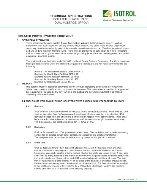
TECHNICAL SPECIFICATIONSISOLATED POWER PANELDUAL VOLTAGE (IPPDV)Medical Division of <strong>Bender</strong> Inc.ISOLATED POWER SYSTEMS EQUIPMENT (Continued)2.3.2 Line Isolation Monitors (LIM)2.3.2.1 Solid state modular assembly of printed circuit boards utilizing SMD technology.2.3.2.2 Continuous monitoring of the impedance of each phase to ground.2.3.2.3 Must be capable of detecting all combinations of capacitive, resistive, balanced,unbalanced and hybrid faults.2.3.2.4 Total Hazard Current (THC) set at the factory to either 2mA or 5mA and shall be fieldadjustable for either milliampere.2.3.2.5 Combined analog and digital display of THC.2.3.2.6 Audible alarm which sounds in the event of a hazardous condition.2.3.2.7 Indicating LEDs to visually indicate the status of the system. Green to indicate“SAFE”, red to indicate“HAZARD” and amber to indicate that the audible alarm is inthe “MUTE” mode. All LEDs and buttons shall be flush with the face of the LIM.2.3.2.8 A “TEST” button on the LIM faces shall be activated to test all LIM functions. It shallnot be possible to leave the button in the “TEST” position.2.3.2.9 The LIMs shall perform an automatic self-calibration and self-check every twelvehours. An error code display shall alert the staff of an anomaly in the LIM / Systemoperation.2.3.2.10 Shall contain overload protection with an automatic reset feature.2.3.2.11 It shall be possible to order the LIMs with an optional RS485 communication portand load monitoring.2.3.2.12 Field terminals shall be available for wiring remote LIM indicators with or without adisplay of THC.2.3.2.13 Shall be UL Recognized as a component.2.3.2.14 Shall have an easy to clean rugged Lexon front foil.2.3.2.15 The LIMs shall be BENDER Model LIM2000 or equivalent.2.3.3 Primary Circuit Breaker2.3.3.1 Shall be be one in each section, two-pole sized in accordance with NFPA 70 (N.E.C.)and UL 1047 Standard and selected based on the transformer primary <strong>voltage</strong> asshown on the contract documents.2.3.3.2 Full size, thermal magnetic type, with minimum 10,000 AIC.2.3.4 Secondary Branch Circuit Breakers2.2.4.1 Two-pole, ampacities, and quantities based on the contract documents for each section.Sized in accordance with NFPA 70 (N.E.C.) and UL 1047 Standard.2.2.4.2 Full size, thermal magnetic type with minimum 10,000 AIC.2.3.5 Reference Ground BusShall contain two (2) reference grounding buses, each with a minimum of one (1) #4-2/0 mainlugs and nineteen (19) #14-4 grounding lugs.Page 3 of 6Rev 3 - 2009 LST
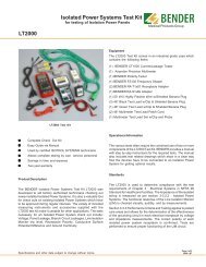
TECHNICAL SPECIFICATIONSISOLATED POWER PANELDUAL VOLTAGE (IPPDV)Medical Division of <strong>Bender</strong> Inc.ISOLATED POWER SYSTEMS EQUIPMENT (Continued)3 REMOTE INDICATORS for LINE ISOLATION MONITORS (OPTIONAL)Provide, where shown on the contract drawings, a single or multiple gang remote indicator whichduplicates the audible and visual alarm indications of the LIM installed in the Isolated Power Panel DualVoltage. The remote indicator shall contain a green “SAFE” LED a red “HAZARD” LED and a “MUTE”button with integral amber LED. The remote indicator shall function as follows:♦ The green LED stays illuminated when the leakage current is within predetermined limits.♦ The green LED extinguishes and the red LED illuminates when the predetermined limit isexceeded; an audible alarm also sounds.♦ When depressed, the “MUTE” button shall mute the audible alarm signal. Actuation of thisbutton shall cause the integral amber LED to illuminate, indicating that the audible alarm hasbeen silenced.♦ When the leakage current has returned to the acceptable limit level, the alarm indicatorsshall automatically reset.♦ Optional THC meter or digital display.4 INSTALLATIONType XHHW wire with crosslinked polyethylene insulation and a dielectric constant of 3.5 or less shall beused.As necessary, special instructions shall be provided for field assembly, mounting and wiring of theequipment. They shall be part of a documentation package which includes three (3) sets of Operation andMaintenance manuals. These manuals shall include written instructions on the care and maintenance ofthe system, spare parts lists and certified “as built” drawings for the material furnished to the facility.Included will be an electrical schematic, an interconnection diagram, an overall outline dimensionaldrawing, and a LIM User Manual.5 TESTING & CERTIFICATIONAn engineer or senior technician shall be provided by the manufacturer for final testing and acceptance ofthe Isolated Power System. The following tasks shall be performed:♦ Simulate faults using the BENDER Type LT2000 Isolated Power Systems Test Kit, or equivalent.Repeat this test at each receptacle to ascertain that the LIM and associated branch circuit arefunctioning properly.♦ Check the calibration of the LIM meter using the LT2000 Isolated Power Systems Test Kit, orequivalent, and record the readings. Record the date and data in a permanent log book.♦ Certify that the system is properly installed and in correct working order.Page 4 of 6Rev 3 - 2009 LST
TECHNICAL SPECIFICATIONSISOLATED POWER PANELDUAL VOLTAGE (IPPDV)Medical Division of <strong>Bender</strong> Inc.ISOLATED POWER SYSTEMS EQUIPMENT (Continued)6 TRAININGAs required, training shall be provided for the hospital maintenance and medical staff covering the correctoperation and routine testing of the Isolated Power System. The function of the LIM will be explained andits test function demonstrated. The hospital maintenance staff shall be instructed on the proper use of thetest equipment. The proper method of recording and logging data shall be explained. Finally, a log bookshall be furnished that contains the data logged by the factory engineer / technician during the initialtesting phase.7 ACCEPTABLE MANUFACTURERSThe equipment shall be provided by ISOTROL or other approved supplier. Other suppliers seeking approvalshall submit proof of their ability to comply with the requirements set forth in this specification.8 APPROVAL SUBMITTALSAs part of the approval process, potential suppliers shall submit pertinent descriptive catalog literature.The following shop drawings shall also be submitted: a) Dimensional data, b) Transformer data, c) LineIsolation Monitor (LIM) details and performance data, d) Product <strong>specifications</strong> from the manufacturer, ande) Load center construction details including method of mounting, type of circuit breaker, current capacity,etc.9 ADDRESS OF MANUFACTURERBENDER / ISOTROLFrom USA, Canada and Mexico:Medical Division of <strong>Bender</strong> Inc. Phone: 800-833-6834700 Fox ChaseCoatesville, PA 19320 USAAll other countries:Phone: 610-383-9655Fax: 610-383-7100Page 5 of 6Rev 3 - 2009 LST
TECHNICAL SPECIFICATIONSISOLATED POWER PANELDUAL VOLTAGE (IPPDV)Medical Division of <strong>Bender</strong> Inc.Notes:Page 6 of 6Rev 3 - 2009 LST


