

A-ISOMETER® IRDH375 IRDH375B - Bender
A-ISOMETER® IRDH375 IRDH375B - Bender
A-ISOMETER® IRDH375 IRDH375B - Bender

You also want an ePaper? Increase the reach of your titles
YUMPU automatically turns print PDFs into web optimized ePapers that Google loves.
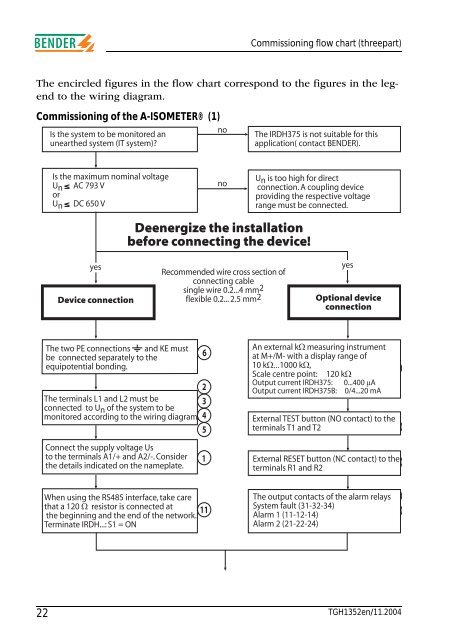
Commissioning flow chart (threepart)The encircled figures in the flow chart correspond to the figures in the legendto the wiring diagram.Commissioning of the A-ISOMETER® (1)noIs the system to be monitored anunearthed system (IT system)?The <strong>IRDH375</strong> is not suitable for thisapplication( contact BENDER).Is the maximum nominal voltageUn AC 793 VorUn DC 650 VnoUn is too high for directconnection. A coupling deviceproviding the respective voltagerange must be connected.Deenergize the installationbefore connecting the device!yesDevice connectionRecommended wire cross section ofconnecting cablesingle wire 0.2...4 mm2flexible 0.2... 2.5 mm2yesOptional deviceconnectionThe two PE connections and KE mustbe connected separately to theequipotential bonding.The terminals L1 and L2 must beconnected to Un of the system to bemonitored according to the wiring diagram.Connect the supply voltage Usto the terminals A1/+ and A2/-. Considerthe details indicated on the nameplate.623451An external kW measuring instrumentat M+/M- with a display range of10 kW...1000 kW,Scale centre point: 120 kWOutput current <strong>IRDH375</strong>: 0...400 mAOutput current <strong>IRDH375</strong>B: 0/4...20 mAExternal TEST button (NO contact) to theterminals T1 and T2External RESET button (NC contact) to theterminals R1 and R2When using the RS485 interface, take carethat a 120 W resistor is connected at 11the beginning and the end of the network.Terminate IRDH...: S1 = ONThe output contacts of the alarm relaysSystem fault (31-32-34)Alarm 1 (11-12-14)Alarm 2 (21-22-24)22 TGH1352en/11.2004


