A-ISOMETER® IRDH375 IRDH375B - Bender
A-ISOMETER® IRDH375 IRDH375B - Bender
A-ISOMETER® IRDH375 IRDH375B - Bender
Create successful ePaper yourself
Turn your PDF publications into a flip-book with our unique Google optimized e-Paper software.
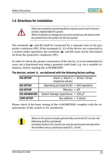
Safety information1.4 Directions for installationOnly one insulation monitoring device may be used in each interconnectedungrounded (IT) system.When insulation or voltage test are to be carried out, the device shallbe isolated from the system for the test period.The terminals and KE shall be connected by a separate wire to the protectiveconductor (PE). If the terminals L1, L2 of the device are connected toa system under operation, the terminals and KE must not be disconnectedfrom the protective conductor (PE).In order to check the proper connection of the device, it is recommended tocarry out a functional test using a genuine earth fault, e.g. via a suitable resistance,before starting the A-ISOMETER®.The devices, variant -4.. are delivered with the following factory setting:ISO SETUP: Alarm 1 / Alarm 2 =40 kΩ / 10 kΩ(response values)ISO SETUP:Operating principle K1/K2 = N/O operationISO SETUP:Memory = offISO ADVANCED: System leakage capacitance = 150 µFCOM SETUP:Bus address = 3 (slave)Please check if the basic setting of the A-ISOMETER® complies with the requirementsof the system to be monitored.When an AC system includes galvanically connected DC circuits, thefollowing shall be considered:Insulation faults in DC circuits can only be monitored correctly whenthe rectifiers carry a continuous load of 5...10 mA.TGH1352en/11.200411


