

A-ISOMETER® IRDH375 IRDH375B - Bender
A-ISOMETER® IRDH375 IRDH375B - Bender
A-ISOMETER® IRDH375 IRDH375B - Bender

You also want an ePaper? Increase the reach of your titles
YUMPU automatically turns print PDFs into web optimized ePapers that Google loves.
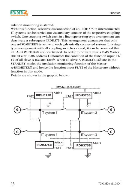
Functionsulation monitoring is started.With this function, selective disconnection of an <strong>IRDH375</strong> in interconnectedIT systems can be carried out via auxiliary contacts of the respective couplingswitch. One coupling switch each in a line-type or ring-type arrangement candeactivate a subsequent <strong>IRDH375</strong>. This arrangement guarantees that onlyone A-ISOMETER® is active in each galvanically connected system. In a ringtypearrangement with all coupling switches closed, it can be assumed thatall A-ISOMETERs® are deactivated. In order to prevent this, a BMS Master(<strong>IRDH375</strong>B BMS address 1) monitors the condition of the function input F1/F2 of all slave A-ISOMETERs®. When all slave A-ISOMETERs® are in theSTANDBY mode, the insulation monitoring function of the MasterA-ISOMETER® and hence the function input F1/F2 of the Master are withoutfunction in this mode.Details are shown in the graphic below.BMS bus (A/B, RS485)F1/F2<strong>IRDH375</strong>BAddr. 1 Addr. 2F1/F2 <strong>IRDH375</strong>BPEPEGIT system 1 IT system 2GGIT system 4IT system 3G<strong>IRDH375</strong>BPEAddr. 4 Addr. 3<strong>IRDH375</strong>BF1/F2 F1/F2PE18 TGH1352en/11.2004


