Elektromotoren und Gerätebau Barleben GmbH ... - Ies-germany.com
Elektromotoren und Gerätebau Barleben GmbH ... - Ies-germany.com
Elektromotoren und Gerätebau Barleben GmbH ... - Ies-germany.com

Create successful ePaper yourself
Turn your PDF publications into a flip-book with our unique Google optimized e-Paper software.
<strong>Elektromotoren</strong> <strong>und</strong><br />
<strong>Gerätebau</strong> <strong>Barleben</strong> <strong>GmbH</strong><br />
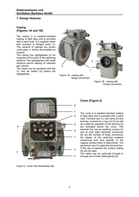
1. Design features<br />
Casing<br />
(Figures 1A and 1B)<br />
The casing is a weather-resistant<br />
casting of light alloy and is provided<br />
with a paint coat. It is supplied either<br />
with screwed or flanged ends (1).<br />
The variants of casings are shown<br />
<strong>und</strong>er para. 4, further are possible on<br />
request.<br />
The casing has sightglasses (2) for<br />
inspection of function of the switching<br />
systems. The sightglasses with scale<br />
divisions permit reading of collected<br />
gas volume.<br />
The relays can be equipped with lids<br />
(3, may be folded up) before the<br />
sightglasses.<br />
9<br />
2<br />
Figure 2 : cover with dismantled cap<br />
3<br />
Figure 1A : casing with<br />
flange connection<br />
4<br />
8<br />
7<br />
5<br />
9<br />
6<br />
1<br />
3<br />
4<br />
1<br />
2<br />
Cover (Figure 2)<br />
Figure 1B : casing with<br />
thread connection<br />
The cover is a weather-resistant casting<br />
of light alloy and is provided with a paint<br />
coat. Terminal box (1), test valve (2) and<br />
test key, covered by a cap nut (3) as well<br />
as a plate for operation of the test key (4)<br />
are arranged above the cover. The<br />
terminal box has an earthing contact (5)<br />
and at most eight electrical connectors<br />
(6). By the number of these connectors<br />
the design of the switching systems<br />
concerning kind and quantity of the<br />
magnet contact tubes is determined. The<br />
aluminium cap (7) seals the terminal box.<br />
If the cap is opened the contact setting<br />
(8) can be seen.<br />
The cable may be optionally brought in<br />
through one of both cable glands (9).
5<br />
6<br />
4<br />
Switchgear (Figures 3A and 3B)<br />
The switchgear has the following main <strong>com</strong>ponents:<br />
Switching system<br />
Carrier, frame<br />
Mechanical testing device.<br />
Whereas the single-float Buchholz relay has only one switching system, the double-float Buchholz relay<br />
has an upper and a lower switching system.<br />
Permanent magnet and float are rigidly linked forming an unit that is movably fitted to the frame together<br />
with mechanical testing device and magnet contact tube(s).<br />
Figure 3A : Switchgear of a single-float<br />
Buchholz relay<br />
Switchgear of a double-float<br />
Buchholz relay:<br />
upper float (1)<br />
lower float (1a)<br />
permanent magnet for upper float (2)<br />
permanent magnet for lower float (2a)<br />
one or two magnet contact tubes for<br />
upper switching system (3)<br />
one or two magnet contact tubes for<br />
lower switching system (3a)<br />
frame (4)<br />
mechanical testing device (5)<br />
damper (6)<br />
The damper is hold by permanent magnets and acts<br />
on the lower switching system.<br />
1<br />
2<br />
3<br />
5<br />
5<br />
6<br />
4<br />
Switchgear of a single-float<br />
Buchholz relay:<br />
float (1)<br />
permanent magnet (2)<br />
one or two magnet contact tubes (3)<br />
frame (4)<br />
mechanical testing device (5)<br />
damper (6)<br />
The damper is hold by permanent magnets.<br />
Figure 3B : Switchgear of a double-float<br />
Buchholz relay<br />
1<br />
2<br />
3<br />
3a<br />
1a<br />
2a
<strong>Elektromotoren</strong> <strong>und</strong><br />
<strong>Gerätebau</strong> <strong>Barleben</strong> <strong>GmbH</strong><br />
2. Function<br />
In the following the operation of a Buchholz relay is explained using the example of a double-float<br />
Buchholz relay.<br />
The relay is built in the connecting pipe between the transformer tank and the conservator. During<br />
normal operation it is filled <strong>com</strong>pletely with insulating liquid. Due to buoyancy the floats are at their top<br />
position. If a fault occurs inside the transformer, the Buchholz relay responds as follows:<br />
Gas accumulation (Figure 4)<br />
Fault: Free gas is available in the insulating<br />
liquid.<br />
Response: The gas in the liquid moves<br />
upwards, accumulates in the Buchholz relay<br />
and displaces the insulating liquid level. The<br />
moving float actuates a switch contact (magnet<br />
contact tube).<br />
An alarm signal is tripped.<br />
The lower float is not affected as from a certain<br />
gas volume the gas flows through a piping to<br />
the conservator.<br />
Insulating liquid loss (Figure 5)<br />
Fault: Insulating liquid loss due to leakage.<br />
Response: As the liquid level falls the top float<br />
moves downward. An alarm is tripped. If the<br />
liquid loss continues, conservator and piping as<br />
well as the Buchholz relay will be emptied.<br />
As the liquid level falls, the lower float moves<br />
downward. The moving float actuates a switch<br />
contact so that the transformer is disconnected.<br />
Insulating liquid flow (Figure 6)<br />
Fault: A spontaneous incident generates a<br />
pressure wave moving in the direction of the<br />
conservator.<br />
Response: The liquid flow reaches a damper<br />
arranged in the liquid flow. If the flow rate<br />
exceeds the operating threshold of the damper,<br />
the latter moves in flow direction. Due to this<br />
movement a switch contact is actuated so that<br />
the transformer is disconnected.<br />
Oil<br />
Gas<br />
Figure 4: Gas accumulation<br />
Air<br />
Figure 5: Insulating liquid loss<br />
Oil<br />
Figure 6: Insulating liquid flow<br />
The upper and lower switching system form a functional unit in the single-float Buchholz relay. In case<br />
of a fault, the single-float Buchholz relay normally isolates the transformer immediately from the mains<br />
system.<br />
6<br />
Oil
3. Tests<br />
To each Buchholz relay a works-number is given mentioned in the test certificate. Furthermore the<br />
tests made with each Buchholz relay<br />
- Dielectric strength test<br />
(AC 2000 V against casing)<br />
- Leakage test<br />
(25 min with 80 o C warm Transformer oil at 0.25 MPa)<br />
- Functional test<br />
(damper setting, switching systems)<br />
are documented in the test certificate.<br />
The Buchholz relays are delivered in transport<br />
cardboards. In the cap nut of the test key there is a<br />
temporary lock for the switching system. This temporary<br />
lock has to be removed before the device is taken into<br />
operation.<br />
With each device we deliver<br />
- operating instructions<br />
- test certificate<br />
in the agreed language.<br />
Flow test<br />
7<br />
DIN EN ISO 9001:2000 certificate<br />
Functional and leakage test
<strong>Elektromotoren</strong> <strong>und</strong><br />
<strong>Gerätebau</strong> <strong>Barleben</strong> <strong>GmbH</strong><br />
4. Type list<br />
4.1. Single-float Buchholz relays thread connection<br />
Type code no.<br />
Works-design.<br />
DIN-design.<br />
01<br />
(AG 25)<br />
(CG 25)<br />
4.1.1. Type 01<br />
f<br />
250<br />
300<br />
350<br />
cm 3<br />
l<br />
Mode of<br />
connection<br />
Connection<br />
thread<br />
G 1 1 /2 “<br />
DN<br />
of pipe<br />
(mm)<br />
d 1<br />
Flange<br />
dimensions<br />
(mm)<br />
d 2 d 3 d 4 d 5 f<br />
Device<br />
dimensions<br />
(mm)<br />
l h 1 h 2<br />
weight<br />
(kg)<br />
Suited for<br />
transformer<br />
ratings of<br />
25 - - - - 16 185 170 62 3.1 < 1600 KVA<br />
170<br />
d1<br />
G11/2"<br />
4.2. Single-float Buchholz relays flange connection<br />
Type code no.<br />
Works-design.<br />
DIN-design.<br />
02<br />
(AF 25/6)<br />
(-)<br />
03<br />
(AF 25/10)<br />
(-)<br />
25<br />
(AF 25)<br />
(-)<br />
Mode of<br />
connection<br />
DN<br />
of pipe<br />
(mm)<br />
d 1<br />
Flange<br />
dimensions<br />
(mm)<br />
d 2 d 3 d 4 d 5 f<br />
Device<br />
dimensions<br />
(mm)<br />
l h 1 h 2<br />
weight<br />
(kg)<br />
Suited for<br />
transformer<br />
ratings of<br />
Flange<br />
4-holes 25 100 75 60 12 12 185 195 62 3.6
4.3. Double-float Buchholz relays thread connection<br />
Type code no.<br />
Works-design.<br />
DIN-design.<br />
04<br />
(BG 25)<br />
(DG 25)<br />
21<br />
(BG 25 S)<br />
(-)<br />
4.3.1. Type 04<br />
4.3.2. Type 21<br />
250<br />
300<br />
350<br />
cm 3<br />
l<br />
250<br />
300<br />
350<br />
cm 3<br />
l<br />
Mode of<br />
connection<br />
Connection<br />
thread<br />
G 1 1 /2 “<br />
Connection<br />
thread<br />
G 1 1 /2 “<br />
f<br />
f<br />
DN<br />
of pipe<br />
(mm)<br />
d 1<br />
Flange<br />
dimensions<br />
(mm)<br />
d 2 d 3 d 4 d 5 f<br />
Device<br />
dimensions<br />
(mm)<br />
l h 1 h 2<br />
weight<br />
(kg)<br />
Suited for<br />
transformer<br />
ratings of<br />
25 - - - - 16 185 235 90 4.2 < 5000 KVA<br />
25 - - - - 16 185 235 90 3.6 < 5000 KVA<br />
170<br />
d1<br />
G11/2"<br />
150<br />
d1<br />
9
<strong>Elektromotoren</strong> <strong>und</strong><br />
<strong>Gerätebau</strong> <strong>Barleben</strong> <strong>GmbH</strong><br />
4.4. Double-float Buchholz relays Flange connection (ro<strong>und</strong>)<br />
Type code no.<br />
Works-design.<br />
DIN-design.<br />
05<br />
(BF 25/6)<br />
(-)<br />
06<br />
(BF 25/10)<br />
(DR 25)<br />
23<br />
(BF25/10S)<br />
(-)<br />
07<br />
(BF 50/6)<br />
(-)<br />
08<br />
(BF 50/10)<br />
(DR 50)<br />
09<br />
(BF 80/10)<br />
(-)<br />
09-26.<br />
(BF80/10/8)<br />
(DR 80)<br />
24<br />
(BF 80/6)<br />
(-)<br />
Mode of<br />
connection<br />
DN<br />
of pipe<br />
(mm)<br />
d 1<br />
Flange<br />
dimensions<br />
(mm)<br />
d 2 d 3 d 4 d 5 f<br />
Device<br />
dimensions<br />
(mm)<br />
l h 1 h 2<br />
weight<br />
(kg)<br />
Suited for<br />
transformer<br />
ratings of<br />
Flange<br />
4-holes 25 100 75 60 12 12 185 235 90 4.4 < 5000 KVA<br />
Flange<br />
4-holes 25 115 85 68 14 18 200 235 90 4.8 5000 KVA<br />
< 10000 KVA<br />
> 5000 KVA<br />
< 10000 KVA<br />
Flange<br />
4-holes 80 200 160 138 18 15 195 265 80 6.2 > 10000 KVA<br />
Flange<br />
8-holes 80 200 160 138<br />
18<br />
M16<br />
15 195 265 80 6.2 > 10000 KVA<br />
Flange<br />
4-holes 80 190 150 130 18 15 195 260 80 6.0 > 10000 KVA<br />
10
4.4.1. Type 05, 06, 07, 08, 09, 24<br />
4.4.2. Type 23<br />
250<br />
300<br />
350<br />
cm 3<br />
l<br />
250<br />
300<br />
350<br />
4.4.3. Type 09-26.<br />
cm 3<br />
l<br />
250<br />
300<br />
350<br />
cm 3<br />
l<br />
f<br />
f<br />
f<br />
170<br />
d1<br />
d4<br />
d3<br />
d2<br />
150<br />
d1<br />
d4<br />
d3<br />
d2<br />
170<br />
d1<br />
d4<br />
d3<br />
d2<br />
M16<br />
11
<strong>Elektromotoren</strong> <strong>und</strong><br />
<strong>Gerätebau</strong> <strong>Barleben</strong> <strong>GmbH</strong><br />
4.5. Double-float Buchholz relays Flange connection (square)<br />
Type code no.<br />
Works-design.<br />
DIN-design.<br />
10<br />
(BF 80/Q)<br />
(DQ 80)<br />
4.5.1. Type 10<br />
250<br />
300<br />
350<br />
cm 3<br />
l<br />
Mode of<br />
connection<br />
Flange<br />
square<br />
4-holes<br />
f<br />
DN<br />
of pipe<br />
(mm)<br />
d 1<br />
Flange<br />
dimensions<br />
(mm)<br />
d 2 d 3 d 4 d 5 f<br />
Device<br />
dimensions<br />
(mm)<br />
l h 1 h 2<br />
weight<br />
(kg)<br />
Suited for<br />
transformer<br />
ratings of<br />
80 125 132 - 18 20 200 235 80 5.0 > 10000 KVA<br />
170<br />
d1<br />
12
4.6. Buchholz relays according to French norm<br />
Type code no.<br />
Works-design.<br />
41<br />
(NF 25)<br />
42<br />
(NF 50)<br />
43<br />
(NF 80)<br />
4.6.1. Types 41, 42, 43<br />
f<br />
250<br />
300<br />
350<br />
cm 3<br />
240<br />
Mode of<br />
connection<br />
DN<br />
of pipe<br />
(mm)<br />
d 1<br />
Flange<br />
dimensions<br />
(mm)<br />
d 2 d 3 d 5 f<br />
Device<br />
dimensions<br />
(mm)<br />
l h 1 h 2<br />
weight<br />
(kg)<br />
Suited for<br />
transforme r<br />
ratings of<br />
Flange<br />
4-holes 25 115 85 14 8 240 235 90 4.2 < 5000 KVA<br />
Flange<br />
4-holes 50 165 125 18 11 240 250 80 5.1<br />
>5000 KVA<br />
< 10000 KVA<br />
Flange<br />
4-holes 80 200 160 18 11 240 265 80 5.5 > 10000 KVA<br />
150<br />
d1<br />
d3<br />
d2<br />
13
<strong>Elektromotoren</strong> <strong>und</strong><br />
<strong>Gerätebau</strong> <strong>Barleben</strong> <strong>GmbH</strong><br />
4.7. Buchholz relays according to British standard<br />
Type code no.<br />
Works-design.<br />
51<br />
(BS 25)<br />
52<br />
(BS 50)<br />
53<br />
(BS 80)<br />
4.7.1. Type 51<br />
250<br />
300<br />
350<br />
4.7.2. Types 52, 53<br />
cm 3<br />
l<br />
250<br />
300<br />
350<br />
cm 3<br />
l<br />
Mode of<br />
connection<br />
Flange<br />
square<br />
4-holes<br />
Flange<br />
6-holes<br />
Flange<br />
6-holes<br />
f<br />
DN<br />
of pipe<br />
(mm)<br />
(inch)<br />
d 1<br />
25<br />
50<br />
80<br />
Flange dimensions<br />
(mm)<br />
(inch)<br />
d 2 d 3 d 5 f<br />
-<br />
-<br />
140<br />
5.51<br />
160<br />
6.30<br />
d1<br />
d3<br />
b<br />
b<br />
d1<br />
d3<br />
d2<br />
72<br />
2.83<br />
110<br />
4.33<br />
130<br />
5.12<br />
14<br />
M10<br />
M10<br />
12<br />
0.47<br />
12<br />
0.47<br />
-<br />
12<br />
0.47<br />
13<br />
0.51<br />
Device dimensions<br />
(mm)<br />
(inch)<br />
b l h 1 h 2 h 3<br />
170<br />
6.69<br />
170<br />
6.69<br />
170<br />
6.69<br />
127<br />
5<br />
185<br />
7.28<br />
185<br />
7.28<br />
235<br />
9.25<br />
235<br />
9.25<br />
240<br />
9.45<br />
90<br />
3.54<br />
80<br />
3.15<br />
80<br />
3.15<br />
80<br />
3.15<br />
80<br />
3.15<br />
80<br />
3.15<br />
weight<br />
(kg)<br />
Suited for<br />
transformer<br />
ratings of<br />
3.7 < 5000 KVA<br />
4.8<br />
> 5000 KVA<br />
< 10000 KVA<br />
5.0 > 10000 KVA
5. Technical data<br />
Table 1<br />
Parameter Data Notes<br />
Nominal voltage<br />
AC 230 V<br />
12 V to 250 V<br />
DC 230 V<br />
12 V to 250 V<br />
Nominal current AC 2 A<br />
0.05 A to 2 A<br />
DC 2 A<br />
0.05 A to 2 A<br />
Contact voltage capacity AC 1000 V --<br />
Insulation voltage capacity AC 2000 V Contact against casing<br />
Temperature range:<br />
- ambient temperature<br />
-45 o C to +55 o C<br />
-49 o F to +131 o F<br />
Others on request<br />
- working range<br />
* temperature of the insulation liquid<br />
* viscosity of the insulation liquid<br />
Shock resistance<br />
- Earthquake / Vibration<br />
-25 o C to +115 o C<br />
-13 o F to +239 o F<br />
1 mm 2 /s to 1100 mm 2 /s<br />
class 4M6<br />
2g (peak value) frequency<br />
range 2Hz to 200 Hz<br />
- Impact<br />
25g / shock duration 11 ms --<br />
Resistance to pressure 0.25 MPa --<br />
Resistance to vacuum < 2.5 kPa --<br />
Insensitivity to<br />
magnetic fields<br />
Switching system:<br />
25 mT --<br />
- Switching contact<br />
magnet contact tube --<br />
- damper<br />
hold by magnets<br />
--<br />
- Response time of damper<br />
< 0.1 s<br />
--<br />
Response of switching system in<br />
case of:<br />
- Gas accumulation<br />
- Flow of insulation liquid<br />
Cable gland<br />
200 cm 3 to 300 cm 3<br />
0.65 m/s + 15 %<br />
1.00 m/s + 15%<br />
1.50 m/s + 15 %<br />
2.00 m/s + 15%<br />
2.50 m/s + 15%<br />
3.00 m/s + 15%<br />
M 20x1.5<br />
--<br />
--<br />
Others on request<br />
Others on request<br />
Nominal installation position 1 o ascending towards<br />
expansion vessel<br />
0 o to 5 o<br />
Degree of protection IP 54 Others on request<br />
Casing colour hammer effect enamel<br />
(silver-grey)<br />
Others on request<br />
15
<strong>Elektromotoren</strong> <strong>und</strong><br />
<strong>Gerätebau</strong> <strong>Barleben</strong> <strong>GmbH</strong><br />
6. Special designs<br />
Special designs are available for use <strong>und</strong>er conditions for which the Buchholz relays of standard<br />
design are not sufficient. The possibilities are mentioned in table 2.<br />
Table 2<br />
Explanation<br />
Identif. no.<br />
Silicone oil is used as insulation liquid 20<br />
Midel oil is used as insulation liquid 21<br />
Climatic version 22<br />
Climatic version (suited for extrem frigidal open-air climates below –45 °C) 34<br />
Climatic version (sea climate) 36<br />
Degree of protection IP 56 38<br />
Degree of protection IP 68 39<br />
Special design approved by RWE, Germany 24<br />
Special design approved by VKR, Germany 30<br />
Casing colour RAL 7001 (silver-grey) 41<br />
Casing colour RAL 7012 (basalt-grey) 42<br />
Casing colour RAL 7022 (umber-grey) 43<br />
Casing colour RAL 7033 (cement-grey) 44<br />
Casing colour RAL 7038 (agate-grey) 45<br />
Upper switching system equipped with two magnet contact tubes 35<br />
Lower switching system equipped with two magnet contact tubes 25<br />
Upper and lower switching system each equipped with two magnet contact<br />
tubes<br />
33<br />
Testing of the switching systems by means of <strong>com</strong>pressed-air and test key 32<br />
Damper hold in response position 23<br />
With oil drain plug 28<br />
Special request (on special agreement with customer) 29<br />
NM series – Buchholz relay with analog measurement of the gas volume 60<br />
Casing colour: two-<strong>com</strong>ponent polyurethane-based structural coating<br />
Attention: For constructional reasons the following special designs are not <strong>com</strong>bined possible in the<br />
same device:<br />
Identif.no. with Identif. no.<br />
23 32<br />
23 33<br />
32 33<br />
6.1. Explanations to Identif. no. 32 For devices in special design with identif.no. 32 there<br />
1 2 3<br />
1 – test valve<br />
is besides the possibility to do the functional test by<br />
means of the test valve (3) additionally the option to<br />
2 – connection for make a functional test of the lower switching system by<br />
pneumatic passing <strong>com</strong>pressed-air in.<br />
testing<br />
For it <strong>com</strong>pressed-air is passed directly to the damper<br />
through the connection for <strong>com</strong>pressed-air (2) and a<br />
Figure 7: cover<br />
3 – test key for<br />
mechanical<br />
testing<br />
pipe mounted inside the Buchholz relay.<br />
After testing by means of <strong>com</strong>pressed-air the Buchholz<br />
relay is to be vented through the test valve (1).<br />
16
7. Ordering data<br />
For placing orders, please, use the following key:<br />
Single-float Buchholz relays Double-float Buchholz relays<br />
XX -XX<br />
. .. XX .-X<br />
0 X<br />
XX -XX . .. XX.-X<br />
X X<br />
Type code no. Type code no.<br />
(see para. 4) (see para. 4)<br />
Special design Special design<br />
(see table 2) (see table 2)<br />
(There are several (There are several<br />
identif. no. possible, identif. no. possible,<br />
always separated by always separated by<br />
a dot.) a dot.)<br />
Damper setting Damper setting<br />
1= 0.65 m/s 1= 0.65 m/s<br />
2 = 1.00 m/s 2 = 1.00 m/s<br />
3 = 1.50 m/s 3 = 1.50 m/s<br />
4 = 2.00 m/s<br />
5 = 2.50 m/s<br />
6 = 3.00 m/s<br />
0 = not occupied Contact setting of<br />
upper switching<br />
system<br />
1 = one NO-contact<br />
2 = one NC-contact<br />
3 = one change-over<br />
contact<br />
4 = two NO-contacts<br />
5 = one NO- and one<br />
NC-contact<br />
Contact setting of Contact setting of<br />
switching system lower switching system<br />
1 = one NO-contact 1 = one NO-contact<br />
2 = one NC-contact 2 = one NC-contact<br />
3 = two NO-contacts 3 = two NO-contacts<br />
4 = two NC-contacts 4 = two NC-contacts<br />
5 = one NO- and one 5 = one NO- and one<br />
NC-contact NC-contact<br />
6 = one change-over 6 =one change-over<br />
contact contact<br />
7 = two change-over<br />
contacts<br />
Important remark: NO = normally-open<br />
NC = normally-closed<br />
Ordering example:<br />
Buchholz relay 10-22.25.28.-313 Explanation:<br />
10<br />
22<br />
25<br />
28<br />
3<br />
1<br />
3<br />
17<br />
= Designation of a double-float Buchholz relay type 10 (BF 80/Q)<br />
= climatic version<br />
= lower switching system equipped with 2 magnet contact tubes<br />
= Oil drain plug<br />
= Damper setting of 1.50 m/s<br />
= contact setting of upper switching system – 1 NO-contact<br />
= contact setting of lower switching system – 2 NO-contacts
<strong>Elektromotoren</strong> <strong>und</strong><br />
<strong>Gerätebau</strong> <strong>Barleben</strong> <strong>GmbH</strong><br />
8. Additional devices<br />
<strong>Elektromotoren</strong> <strong>und</strong> <strong>Gerätebau</strong> <strong>Barleben</strong> <strong>GmbH</strong> may supply further products for protection and<br />
supervision of liquid-insulated transformers.<br />
Please, ask for our separate catalogues.<br />
designation<br />
ZG 1.2.<br />
ZG 3.1.<br />
ZG 4.1.<br />
ZG 5.1.<br />
ZG 5.2.<br />
ZG 6.1.<br />
BGS<br />
BGT<br />
ÜRF 25/10<br />
SG 25<br />
SF 25/10<br />
description<br />
Gas sampling device<br />
The device is mounted at the transformer and connected to the Buchholz relay by<br />
means of a pipe. It allows to sample the relay gas at normal operating level.<br />
A manual and an automatic version are available.<br />
The devices can be delivered with a lockable box.<br />
Gas testing device<br />
The device serves to analyse the relay gas by means of two test fluids. It can be<br />
mounted directly on the Buchholz relay as well as on the Gas sampling device<br />
ZG 1.2.<br />
Reflux lock<br />
The device prevents that the insulation liquid gets into the Gas testing device.<br />
Test pump<br />
The device serves to check the upper switching system by means of air.<br />
- manual-actuated<br />
- foot-actuated<br />
Oil sampling device<br />
The device is connected to the Buchholz relay by means of a pipe and serves to<br />
take oil samples (can be used for Buchholz relays with oil drain plug).<br />
Buchholz gas sampler<br />
The Buchholz gas sampler can be connected to the Buchholz relay or to the Gas<br />
sampling device. It serves to sample and to transport safe the gas.<br />
Buchholz gas tester<br />
The Buchholz gas tester serves to analyze the Buchholz gas regarding the<br />
hydrogen concentration. For other gas testing devices, please, contact us.<br />
Monitoring relay for tap changer<br />
Oil flow indicator<br />
- with thread connection<br />
- with flange connection<br />
18