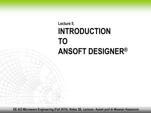
INTRODUCTION TO ANSOFT DESIGNER®
INTRODUCTION TO ANSOFT DESIGNER®
INTRODUCTION TO ANSOFT DESIGNER®

You also want an ePaper? Increase the reach of your titles
YUMPU automatically turns print PDFs into web optimized ePapers that Google loves.
Lecture 5. <strong>INTRODUCTION</strong> <strong>TO</strong> <strong>ANSOFT</strong> DESIGNER ®<br />
Lecture 5.<br />
<strong>INTRODUCTION</strong><br />
<strong>TO</strong><br />
<strong>ANSOFT</strong> DESIGNER ®<br />
EE 433 Microwave Engineering (Fall 2010): Notes 3B, Lecturer: Assist prof dr Moamer Hasanovic
Lecture 5. <strong>INTRODUCTION</strong> <strong>TO</strong> <strong>ANSOFT</strong> DESIGNER ®<br />
Software Tools for RF/Microwave Design<br />
RF designers nowadays extensively use various simulation tools when<br />
designing RF components.<br />
There are many commercial software packages for simulation of RF circuits that<br />
may be obtained on the market. Companies such as Ansoft Corporation,<br />
Agilent Technologies, Sonnet, Eagleware, etc. offer simulation programs<br />
that very often incorporate circuit modeling, full electromagnetic simulation, as<br />
well as statistical analysis of RF components and systems.<br />
We will give a brief overview of two commercial RF simulation packages offered<br />
by Ansoft Corporation:<br />
Ansoft Designer®<br />
Ansoft HFSS®<br />
EE 433 Microwave Engineering (Fall 2010): Notes 3B, Lecturer: Assist prof dr Moamer Hasanovic
Lecture 5. <strong>INTRODUCTION</strong> <strong>TO</strong> <strong>ANSOFT</strong> DESIGNER ®<br />
Software Tools for RF/Microwave Design (cont.)<br />
Ansoft Designer ® is an integrated schematic and<br />
design tool used for complex analog, RF and mixed<br />
signal applications. It enables RF engineers to<br />
design, optimize, and validate component, circuit,<br />
and system performance long before building a<br />
prototype of RF circuit.<br />
Ansoft HFSS ® is a full 3D electromagnetic simulator<br />
widely used for the design of various passive and<br />
active RF components, interconnects, antennas, and<br />
RFIC packages. It is based on finite element<br />
numerical method and provides a user friendly<br />
graphic user interface.<br />
EE 433 Microwave Engineering (Fall 2010): Notes 3B, Lecturer: Assist prof dr Moamer Hasanovic
Lecture 5. <strong>INTRODUCTION</strong> <strong>TO</strong> <strong>ANSOFT</strong> DESIGNER ®<br />
This is how Ansoft Designer® Desktop looks after the program is started:<br />
Software Tools for RF/Microwave Design (cont.)<br />
Click on this icon to introduce a circuit editor<br />
This pop-up<br />
window shows up<br />
letting you choose<br />
layout properties of<br />
your RF circuit (we<br />
will choose ‘None’<br />
option)<br />
EE 433 Microwave Engineering (Fall 2010): Notes 3B, Lecturer: Assist prof dr Moamer Hasanovic
Lecture 5. <strong>INTRODUCTION</strong> <strong>TO</strong> <strong>ANSOFT</strong> DESIGNER ®<br />
The schematic editor window allows you to place components and wire them<br />
together. You can move components by simply selecting and dragging them. Copy<br />
and paste can be used on components and their wires within the schematic editor.<br />
You can also copy<br />
and paste to other<br />
schematics.<br />
Click on ‘Components’ to import<br />
various models of RF components<br />
into your circuit model<br />
EE 433 Microwave Engineering (Fall 2010): Notes 3B, Lecturer: Assist prof dr Moamer Hasanovic
Lecture 5. <strong>INTRODUCTION</strong> <strong>TO</strong> <strong>ANSOFT</strong> DESIGNER ®<br />
Choose a component and simply<br />
drag it into the schematic editor<br />
window<br />
EE 433 Microwave Engineering (Fall 2010): Notes 3B, Lecturer: Assist prof dr Moamer Hasanovic
Lecture 5. <strong>INTRODUCTION</strong> <strong>TO</strong> <strong>ANSOFT</strong> DESIGNER ®<br />
Position cursor over the end of the<br />
component and drag to the end of<br />
the subsequent component to wire<br />
the two.<br />
EE 433 Microwave Engineering (Fall 2010): Notes 3B, Lecturer: Assist prof dr Moamer Hasanovic
Lecture 5. <strong>INTRODUCTION</strong> <strong>TO</strong> <strong>ANSOFT</strong> DESIGNER ®<br />
Double-click on the component to<br />
edit its properties (impedance,<br />
electrical length, etc)<br />
EE 433 Microwave Engineering (Fall 2010): Notes 3B, Lecturer: Assist prof dr Moamer Hasanovic
Lecture 5. <strong>INTRODUCTION</strong> <strong>TO</strong> <strong>ANSOFT</strong> DESIGNER ®<br />
Click on this icon to introduce<br />
ports. Double-click on a port opens<br />
a window that enables editing<br />
properties of the port.<br />
EE 433 Microwave Engineering (Fall 2010): Notes 3B, Lecturer: Assist prof dr Moamer Hasanovic
Lecture 5. <strong>INTRODUCTION</strong> <strong>TO</strong> <strong>ANSOFT</strong> DESIGNER ®<br />
In order to define operating frequency range, click on ‘Analysis’.<br />
EE 433 Microwave Engineering (Fall 2010): Notes 3B, Lecturer: Assist prof dr Moamer Hasanovic
Lecture 5. <strong>INTRODUCTION</strong> <strong>TO</strong> <strong>ANSOFT</strong> DESIGNER ®<br />
Click on this icon to perform analysis of your circuit model!<br />
EE 433 Microwave Engineering (Fall 2010): Notes 3B, Lecturer: Assist prof dr Moamer Hasanovic
Lecture 5. <strong>INTRODUCTION</strong> <strong>TO</strong> <strong>ANSOFT</strong> DESIGNER ®<br />
Right-click on ‘Results’ to define<br />
parameters to be displayed and to<br />
display results of your simulation.<br />
EE 433 Microwave Engineering (Fall 2010): Notes 3B, Lecturer: Assist prof dr Moamer Hasanovic
Lecture 5. <strong>INTRODUCTION</strong> <strong>TO</strong> <strong>ANSOFT</strong> DESIGNER ®<br />
Instead of an ideal distributed component<br />
with electrical parameters (such as<br />
characteristic impedance and electrical<br />
length), we can also define components with<br />
physical parameters (stripline in this case).<br />
EE 433 Microwave Engineering (Fall 2010): Notes 3B, Lecturer: Assist prof dr Moamer Hasanovic
Lecture 5. <strong>INTRODUCTION</strong> <strong>TO</strong> <strong>ANSOFT</strong> DESIGNER ®<br />
Double-click on a physical component<br />
opens up a window that enables<br />
definition of component parameters.<br />
EE 433 Microwave Engineering (Fall 2010): Notes 3B, Lecturer: Assist prof dr Moamer Hasanovic
Lecture 5. <strong>INTRODUCTION</strong> <strong>TO</strong> <strong>ANSOFT</strong> DESIGNER ®<br />
Click on ‘Substrate’ to define<br />
properties of substrate.<br />
EE 433 Microwave Engineering (Fall 2010): Notes 3B, Lecturer: Assist prof dr Moamer Hasanovic
Lecture 5. <strong>INTRODUCTION</strong> <strong>TO</strong> <strong>ANSOFT</strong> DESIGNER ®<br />
Click on ‘TRL’ to open a Transmission tool that<br />
performs necessary transformations of electrical into<br />
physical parameters and vice versa.<br />
EE 433 Microwave Engineering (Fall 2010): Notes 3B, Lecturer: Assist prof dr Moamer Hasanovic
Lecture 5. <strong>INTRODUCTION</strong> <strong>TO</strong> <strong>ANSOFT</strong> DESIGNER ®<br />
Analysis of the new physical circuit as well as<br />
displaying results is described before.<br />
EE 433 Microwave Engineering (Fall 2010): Notes 3B, Lecturer: Assist prof dr Moamer Hasanovic
Lecture 5. <strong>INTRODUCTION</strong> <strong>TO</strong> <strong>ANSOFT</strong> DESIGNER ®<br />
You can further improve your circuit model and<br />
bring it closer to the actual geometrical model<br />
of your RF component by adding various<br />
models of RF discontinuities.<br />
EE 433 Microwave Engineering (Fall 2010): Notes 3B, Lecturer: Assist prof dr Moamer Hasanovic
Lecture 5. <strong>INTRODUCTION</strong> <strong>TO</strong> <strong>ANSOFT</strong> DESIGNER ®<br />
EE 433 Microwave Engineering (Fall 2010): Notes 3B, Lecturer: Assist prof dr Moamer Hasanovic
Lecture 5. <strong>INTRODUCTION</strong> <strong>TO</strong> <strong>ANSOFT</strong> DESIGNER ®<br />
EE 433 Microwave Engineering (Fall 2010): Notes 3B, Lecturer: Assist prof dr Moamer Hasanovic
Lecture 5. <strong>INTRODUCTION</strong> <strong>TO</strong> <strong>ANSOFT</strong> DESIGNER ®<br />
This circuit simulator also lets you<br />
define variables and optimize them for<br />
a predefined goals (double-click on a<br />
component which parameters you<br />
want to edit).<br />
EE 433 Microwave Engineering (Fall 2010): Notes 3B, Lecturer: Assist prof dr Moamer Hasanovic
Lecture 5. <strong>INTRODUCTION</strong> <strong>TO</strong> <strong>ANSOFT</strong> DESIGNER ®<br />
Next class we will build a full 3D geometrical model of the divider whose circuit<br />
model we developed today.<br />
EE 433 Microwave Engineering (Fall 2010): Notes 3B, Lecturer: Assist prof dr Moamer Hasanovic