Detailed specification - DAN SWIFT - J. Lauritzen
Detailed specification - DAN SWIFT - J. Lauritzen
Detailed specification - DAN SWIFT - J. Lauritzen

Create successful ePaper yourself
Turn your PDF publications into a flip-book with our unique Google optimized e-Paper software.
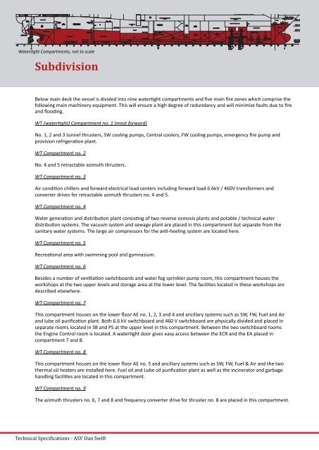
Waterght Compartments, not to scale<br />
Subdivision<br />
Below main deck the vessel is divided into nine waterght compartments and five main fire zones which comprise the<br />
following main machinery equipment. This will ensure a high degree of redundancy and will minimize faults due to fire<br />
and flooding.<br />
WT (waterght) Compartment no. 1 (most forward)<br />
No. 1, 2 and 3 tunnel thrusters, SW cooling pumps, Central coolers, FW cooling pumps, emergency fire pump and<br />
provision refrigeraon plant.<br />
WT Compartment no. 2<br />
No. 4 and 5 retractable azimuth thrusters.<br />
WT Compartment no. 3<br />
Air condion chillers and forward electrical load centers including forward load 6.6kV / 460V transformers and<br />
converter drives for retractable azimuth thrusters no. 4 and 5.<br />
WT Compartment no. 4<br />
Water generaon and distribuon plant consisng of two reverse osmosis plants and potable / technical water<br />
distribuon systems. The vacuum system and sewage plant are placed in this compartment but separate from the<br />
sanitary water systems. The large air compressors for the an-heeling system are located here.<br />
WT Compartment no. 5<br />
Recreaonal area with swimming pool and gymnasium.<br />
WT Compartment no. 6<br />
Besides a number of venlaon switchboards and water fog sprinkler pump room, this compartment houses the<br />
workshops at the two upper levels and storage area at the lower level. The facilies located in these workshops are<br />
described elsewhere.<br />
WT Compartment no. 7<br />
This compartment houses on the lower floor AE no. 1, 2, 3 and 4 and ancillary systems such as SW, FW, Fuel and Air<br />
and lube oil purificaon plant. Both 6.6 kV switchboard and 460 V switchboard are physically divided and placed in<br />
separate rooms located in SB and PS at the upper level in this compartment. Between the two switchboard rooms<br />
the Engine Control room is located. A waterght door gives easy access between the ECR and the EA placed in<br />
compartment 7 and 8.<br />
WT Compartment no. 8<br />
This compartment houses on the lower floor AE no. 5 and ancillary systems such as SW, FW, Fuel & Air and the two<br />
thermal oil heaters are installed here. Fuel oil and Lube oil purificaon plant as well as the incinerator and garbage<br />
handling facilies are located in this compartment.<br />
WT Compartment no. 9<br />
The azimuth thrusters no. 6, 7 and 8 and frequency converter drive for thruster no. 8 are placed in this compartment.<br />
Technical Speciications - ASV Dan Swift

![41367 JL News 11 [6].indd - J. Lauritzen](https://img.yumpu.com/11983725/1/166x260/41367-jl-news-11-6indd-j-lauritzen.jpg?quality=85)