LA - SUSS MicroOptics
LA - SUSS MicroOptics
LA - SUSS MicroOptics

Create successful ePaper yourself
Turn your PDF publications into a flip-book with our unique Google optimized e-Paper software.
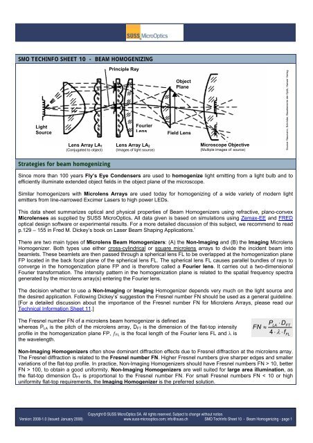
SMO TECHINFO SHEET 10 - BEAM HOMOGENIZING<br />
Light<br />
Source<br />
Lens Array <strong>LA</strong>1<br />
(Conjugated to object)<br />
Strategies for beam homogenizing<br />
Principle Ray<br />
Verlag<br />
Object<br />
Plane<br />
Hanser Optik, der Bauelemente<br />
Fourier<br />
Schröder,<br />
Lens Field Lens<br />
Naumann,<br />
Lens Array <strong>LA</strong>2<br />
Microscope Objective<br />
(Images of light source) (Multiple images of source)<br />
Source:<br />
)<br />
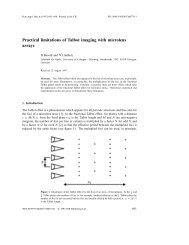
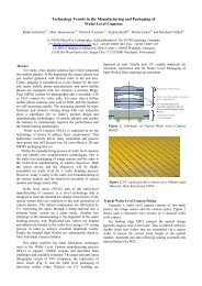
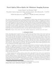
Since more than 100 years Fly’s Eye Condensers are used to homogenize light emitting from a light bulb and to<br />
efficiently illuminate extended object fields in the object plane of the microscope.<br />
Similar homogenizers with Microlens Arrays are used today for homogenizing of a wide variety of modern light<br />
emitters from line-narrowed Excimer Lasers to high power LEDs.<br />
This data sheet summarizes optical and physical properties of Beam Homogenizers using refractive, plano-convex<br />
Microlenses as supplied by <strong>SUSS</strong> <strong>MicroOptics</strong>. All data given is based on simulations using Zemax-EE and FRED<br />
optical design software or experimental results. For a more detailed discussion of this subject, we recommend to read<br />
p.129 – 155 in Fred M. Dickey’s book on Laser Beam Shaping Applications. i<br />
There are two main types of Microlens Beam Homogenizers: (A) the Non-Imaging and (B) the Imaging Microlens<br />
Homogenizer. Both types use either cross-cylindrical or square microlens arrays to divide the incident beam into<br />
beamlets. These beamlets are then passed through a spherical lens FL to be overlapped at the homogenization plane<br />
FP located in the back focal plane of the spherical lens FL. The spherical lens FL causes parallel bundles of rays to<br />
converge in the homogenization plane FP and is therefore called a Fourier lens. It carries out a two-dimensional<br />
Fourier transformation. The intensity pattern in the homogenization plane is related to the spatial frequency spectra<br />
generated by the microlens array(s) entering the Fourier lens.<br />
The decision whether to use a Non-Imaging or Imaging Homogenizer depends very much on the light source and<br />
the desired application. Following Dickey’s i suggestion the Fresnel number FN should be used as a general guideline.<br />
[For a detailed discussion about the importance of the Fresnel number FN for Microlens Arrays, please read our<br />
Technical Information Sheet 11.]<br />
The Fresnel number FN of a microlens beam homogenizer is defined as<br />
whereas P<strong>LA</strong> is the pitch of the microlens array, DFT is the dimension of the flat-top intensity<br />
profile in the homogenization plane FP, ƒFL is the focal length of the Fourier lens FL and λ is<br />
the wavelength.<br />
P<strong>LA</strong><br />
⋅D<br />
FN ≈<br />
4<br />
⋅ λ ⋅f<br />
Non-Imaging Homogenizers often show dominant diffraction effects due to Fresnel diffraction at the microlens array.<br />
The Fresnel diffraction is related to the Fresnel number FN. Higher Fresnel numbers give sharper edges and smaller<br />
variations of the flat-top profile. In practice, Non-Imaging Homogenizers should have Fresnel numbers FN > 10, better<br />
FN > 100, to obtain a good uniformity. Non-Imaging Homogenizers are well suited for large area illumination, as<br />
the flat-top dimension DFT is proportional to the Fresnel number FN. For small Fresnel numbers FN < 10 or high<br />
uniformity flat-top requirements, the Imaging Homogenizer is the preferred solution.<br />
Copyright © <strong>SUSS</strong> <strong>MicroOptics</strong> SA. All rights reserved. Subject to change without notice.<br />
Version: 2008-1.0 (Issued: January 2008) www.suss-microoptics.com; info@suss.ch SMO TechInfo Sheet 10 - Beam Homogenizing - page 1<br />
FT<br />
FL
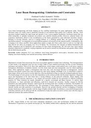
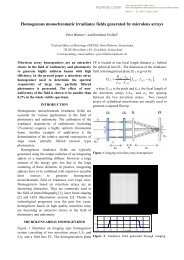
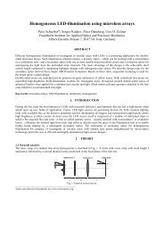
A) NON-IMAGING HOMOGENIZER: One Microlens Array <strong>LA</strong>1, spherical lens FL<br />
The homogenization plane FP is located at one focal length distance ƒFP behind the spherical lens FL. The<br />
dimensions of the beam in the homogenized plane are given by DFT.<br />
ØIN<br />
P<strong>LA</strong>1<br />
<strong>LA</strong>1 FL FP<br />
ƒ1<br />
s<br />
ƒFL<br />
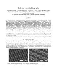
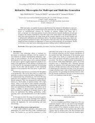
B) IMAGING HOMOGENIZER: Two Microlens Arrays <strong>LA</strong>1 and <strong>LA</strong>2, spherical lens FL<br />
The homogenization plane FP is located at one focal length distance ƒFP behind the spherical lens FL. The<br />
dimensions of the beam in the homogenized plane are given by DFT.<br />
ØIN<br />
P<strong>LA</strong>1<br />
<strong>LA</strong>1 FL<br />
<strong>LA</strong>2<br />
ƒ1<br />
a12 s<br />
The Imaging Homogenizer uses the first microlens array <strong>LA</strong>1 to divide the incident beam into multiple beamlets. The<br />
second microlens array <strong>LA</strong>2, in combination with the spherical lens FL, acts as an array of objective lenses that<br />
superimposes the images of each of the beamlets in the first array onto the homogenization plane FP.<br />
The size of the flat-top now depends on the separation a12 of the two microlens array. This allows a variation of the<br />
flat-top dimensions be shifting the position of the second microlens array. However, care must be taken not to<br />
damage the second microlens array by focusing high-power laser beams into the lens material or to generate<br />
crosstalk by overfilling the lens apertures of the second microlens array.<br />
For Imaging Homogenizers the divergence θ (half angle) after the homogenized plane is given by<br />
( ØIN<br />
+ DFT<br />
− 2P<strong>LA</strong><br />
)<br />
( D > P )<br />
1<br />
tanθ<br />
< ,<br />
2 f<br />
FL<br />
<strong>LA</strong><br />
ƒFL<br />
FP<br />
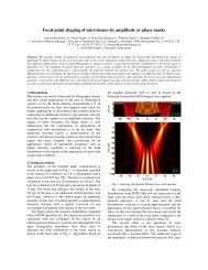
Usually, Imaging Homogenizers consist of two similar microlens arrays with identical lens pitch. Square-type lens<br />
apertures generate a square flat top or top hat intensity distribution in the Fourier plane. Circular or hexagonal<br />
microlenses will generate a circular respectively hexagonal flat-top.<br />
DFT<br />
DFT<br />
where<br />
Copyright © <strong>SUSS</strong> <strong>MicroOptics</strong> SA. All rights reserved. Subject to change without notice.<br />
Version: 2008-1.0 (Issued: January 2008) www.suss-microoptics.com; info@suss.ch SMO TechInfo Sheet 10 - Beam Homogenizing - page 2<br />
D<br />
a<br />
FT<br />
12<br />
= P<br />
<strong>LA</strong>1<br />
f<br />
f<br />
<strong>LA</strong>1<br />
f<br />
<strong>LA</strong>1<br />
FL<br />
< a<br />
⋅f<br />
12<br />
<strong>LA</strong>2<br />
< f<br />
D<br />
FT<br />
P<strong>LA</strong>1<br />
⋅f<br />
=<br />
f<br />
[ ( f + f ) − a ]<br />
<strong>LA</strong>1<br />
<strong>LA</strong>1<br />
+ f<br />
1<br />
<strong>LA</strong>2<br />
<strong>LA</strong>2<br />
: separation of <strong>LA</strong> and <strong>LA</strong><br />
2<br />
12<br />
( ØIN<br />
+ DFT<br />
)<br />
( D < P )<br />
1<br />
tanθ<br />
≈ ,<br />
2 f<br />
FL<br />
<strong>LA</strong><br />
<strong>LA</strong>1<br />
FL
Square Microlens Array<br />
Microlens Array <strong>LA</strong>1<br />
P<strong>LA</strong><br />
Although these two basic principles of Microlens Beam Homogenizers seem to be quite simple, the proper system<br />
layout for a specific illumination task is not always easy to find. There are no common cookbook recipes that work out<br />
for all the light sources and lasers.<br />
C) HOMOGENIZER DESIGN CONSIDERATIONS<br />
We will now explain and discuss some additional design considerations that might be helpful for the layout of a<br />
Microlens Beam Homogenizer system.<br />
Microlens pitch: For standard laser beams, the overlay of some 9-10 microlenses is usually sufficient to achieve a<br />
good flat top uniformity. Consequently, the beam diameter ØIN constrains the maximum microlens pitch P<strong>LA</strong>1 ≤ ØIN/3.<br />
Typical homogenizers use 5x5 to 7x7 microlenses, but a larger number of microlenses do not have negative effects.<br />
For large Excimer laser beams, homogenizers with many thousands of microlenses provide excellent flat-top profiles.<br />
Diffraction effects: For small microlens apertures and a long focal length, i.e. for microlens beam homogenizers with a<br />
Fresnel Number FN < 10, the flat top profile might be distorted by Fresnel diffraction at the lens apertures. Thus for<br />
small laser beams a beam expander is usually the better solution than using microlens arrays with a very small lens<br />
pitch.<br />
Crosstalk: For Imaging Homogenizers the diameter of the individual beamlets at the second microlens array <strong>LA</strong>2 must<br />
be smaller than the lens pitch to avoid an overfilling of the lens aperture and the loss of light. For a collimated laser<br />
beam, the separation of the two microlens arrays is given by f <strong>LA</strong>1<br />
< a < f<strong>LA</strong>1<br />
+ f . For laser beams with a significant<br />
<strong>LA</strong>2<br />
beam divergence the diameter of the beamlets at the second microlens array scales with the beam divergence. The<br />
maximum allowed beam divergence for a given microlens homogenizer is tanθ ≤ P<strong>LA</strong><br />
( 2 f <strong>LA</strong>1)<br />
for a = f . <strong>LA</strong>1<br />
Damage: For high-power laser beams, a focusing into the material of the second microlens array or the spherical<br />
lens must be avoided. An additional diffuser might be used to properly fill the aperture of the second microlens array.<br />
Divergence: The beam divergence is increased by the beam homogenizer.<br />
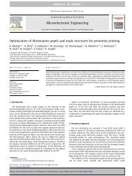
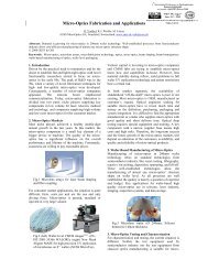
Coherence: Fulfilling the image condition for Imaging Beam Homogenizers holds a severe disadvantage for<br />
coherent laser beams. Microlens arrays are periodic structures, where the pitch P<strong>LA</strong>1 is the grating period. Each<br />
microlens array will behave like a diffraction grating and will generate diffraction orders with a period ΛFP = ƒFL⋅λ/PL1<br />
in the homogenization plane FP.<br />
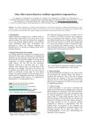
Distorted flat top profile for a coherent laser beam due<br />
to grating diffraction.<br />
FP: Overlay of magnified lens apertures<br />
A rotating diffuser reduces the coherence and<br />
provides a perfect flat top for coherent lasers.<br />
Copyright © <strong>SUSS</strong> <strong>MicroOptics</strong> SA. All rights reserved. Subject to change without notice.<br />
Version: 2008-1.0 (Issued: January 2008) www.suss-microoptics.com; info@suss.ch SMO TechInfo Sheet 10 - Beam Homogenizing - page 3<br />
DFT<br />
Measured profile in FP
The flat top intensity pattern of a coherent laser beam is distorted by an array of spots with the diameter δx =<br />
2ƒFL⋅λ/ØFL, whereas ØFL is the diameter of the Fourier Lens FL.<br />
These distortions by grating diffraction and interference could be reduced by different measures:<br />
- A larger microlens pitch P<strong>LA</strong>1 leads to a finer period ΛFP in the Fourier plane.<br />
- A detuning of beam homogenizer components, e.g. a shift of the microlens arrays or the working plane out of its<br />
correct positions allows reducing the modulation of the flat top profile.<br />
- A rotating ground glass diffuser plate to reduce the coherence of a cw-laser.<br />
ROTATING DIFFUSER: For coherent cw-lasers, a rotating diffuser plate is the appropriated mean to avoid the<br />
grating diffraction. Placing the diffuser at the focus of the beam, e.g. by using a beam expander in front of the<br />
homogenizer, reduces the coherence by creating a new extended light sources, whereas the size of the source is<br />
equal to the spot diameter on the rotating diffuser.<br />
Unfortunately rotating diffusers do not work for pulsed lasers like Nd:YAG with picosecond laser pulses. Different<br />
measures, such as stair case beam splitters are applied.<br />
Reference: i F.M. Dickey, S.C. Hoswade, D.L. Shealy, Laser Beam Shaping Applications, Taylor & Francis, ISBN 0-8247-5941<br />
Copyright © <strong>SUSS</strong> <strong>MicroOptics</strong> SA. All rights reserved. Subject to change without notice.<br />
Version: 2008-1.0 (Issued: January 2008) www.suss-microoptics.com; info@suss.ch SMO TechInfo Sheet 10 - Beam Homogenizing - page 4