State Based Control of Timed Discrete Event Systems using Binary ...
State Based Control of Timed Discrete Event Systems using Binary ...
State Based Control of Timed Discrete Event Systems using Binary ...

You also want an ePaper? Increase the reach of your titles
YUMPU automatically turns print PDFs into web optimized ePapers that Google loves.
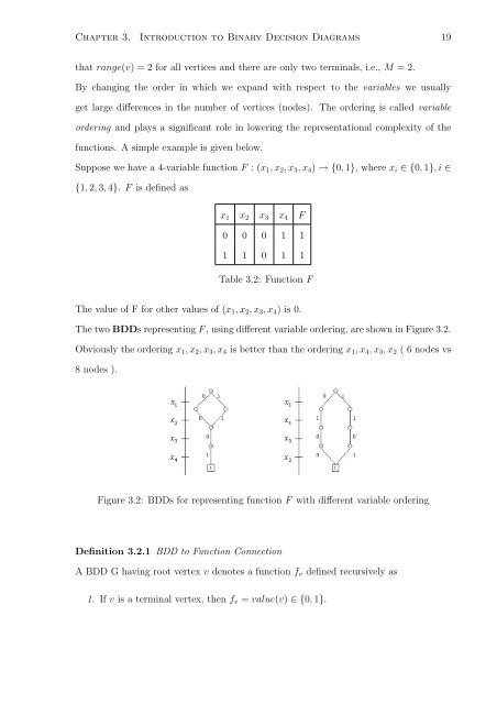
Chapter 3. Introduction to <strong>Binary</strong> Decision Diagrams 19that range(v) = 2 for all vertices and there are only two terminals, i.e., M = 2.By changing the order in which we expand with respect to the variables we usuallyget large differences in the number <strong>of</strong> vertices (nodes). The ordering is called variableordering and plays a significant role in lowering the representational complexity <strong>of</strong> thefunctions. A simple example is given below.Suppose we have a 4-variable function F : (x 1 , x 2 , x 3 , x 4 ) → {0, 1}, where x i ∈ {0, 1}, i ∈{1, 2, 3, 4}. F is defined asx 1 x 2 x 3 x 4 F0 0 0 1 11 1 0 1 1Table 3.2: Function FThe value <strong>of</strong> F for other values <strong>of</strong> (x 1 , x 2 , x 3 , x 4 ) is 0.The two BDDs representing F , <strong>using</strong> different variable ordering, are shown in Figure 3.2.Obviously the ordering x 1 , x 2 , x 3 , x 4 is better than the ordering x 1 , x 4 , x 3 , x 2 ( 6 nodes vs8 nodes ).Figure 3.2: BDDs for representing function F with different variable orderingDefinition 3.2.1 BDD to Function ConnectionA BDD G having root vertex v denotes a function f v defined recursively as1. If v is a terminal vertex, then f v = value(v) ∈ {0, 1}.