Duplex Fiber Repeater - FOSTDRP - Datasheet - Delmation
Duplex Fiber Repeater - FOSTDRP - Datasheet - Delmation
Duplex Fiber Repeater - FOSTDRP - Datasheet - Delmation

You also want an ePaper? Increase the reach of your titles
YUMPU automatically turns print PDFs into web optimized ePapers that Google loves.
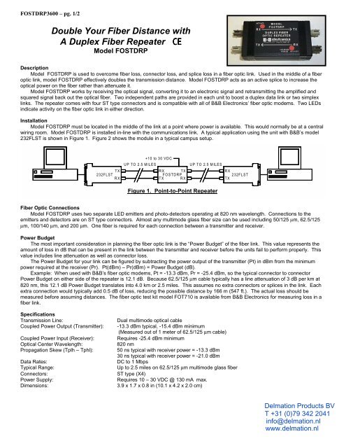
<strong>FOSTDRP</strong>3600 – pg. 1/2Double Your <strong>Fiber</strong> Distance withA <strong>Duplex</strong> <strong>Fiber</strong> <strong>Repeater</strong> CEModel <strong>FOSTDRP</strong>DescriptionModel <strong>FOSTDRP</strong> is used to overcome fiber loss, connector loss, and splice loss in a fiber optic link. Used in the middle of a fiberoptic link, model <strong>FOSTDRP</strong> effectively doubles the transmission distance. Model <strong>FOSTDRP</strong> acts as an active splice to increase theoptical power on the fiber rather than attenuate it.Model <strong>FOSTDRP</strong> works by receiving the optical signal, converting it to an electronic signal and retransmitting the amplified andsquared signal back out the optical fiber. Two independent paths are provided in each unit to boost a duplex data link or two simplexlinks. The repeater comes with four ST type connectors and is compatible with all of B&B Electronics’ fiber optic modems. Two LEDsindicate activity on the fiber optic link in either direction.InstallationModel <strong>FOSTDRP</strong> must be located in the middle of the link at a point where power is available. This would normally be at a centralwiring room. Model <strong>FOSTDRP</strong> is installed in-line with the communications link. A typical application using the unit with B&B’s model232FLST is shown in Figure 1. Figure 2 shows the module in a typical campus setup.232FLST TXRX+10 to 30 VDCUP TO 2.5 MILESRXTX<strong>FOSTDRP</strong>TXRXUP TO 2.5 MILESRX232FLSTTXFigure 1. Point-to-Point <strong>Repeater</strong><strong>Fiber</strong> Optic ConnectionsModel <strong>FOSTDRP</strong> uses two separate LED emitters and photo-detectors operating at 820 nm wavelength. Connections to theemitters and detectors are on ST type connectors. Almost any multimode glass fiber size can be used including 50/125 µm, 62.5/125µm, 100/140 µm, and 200 µm. One fiber is required for each connection between a transmitter and receiver.Power BudgetThe most important consideration in planning the fiber optic link is the “Power Budget” of the fiber link. This value represents theamount of loss in dB that can be present in the link between the transmitter and receiver before the units fail to perform properly. Thisvalue includes line attenuation as well as connector loss.The Power Budget for your link can be figured by subtracting the power output of the transmitter (Pt) in dBm from the minimumpower required at the receiver (Pr). Pt(dBm) – Pr(dBm) = Power Budget (dB).Example: When used with B&B’s fiber optic modems, Pt = -13.3 dBm, Pr = -25.4 dBm, so the typical connector to connectorPower Budget on either side of the repeater is 12.1 dB. Because 62.5/125 µm cable typically has a line attenuation of 3 dB per km at820 nm, this 12.1 dB Power Budget translates into 4.0 km or 2.5 miles. This assumes no extra connectors or splices in the link. Eachextra connection would typically add 0.5 dB of loss, reducing the possible distance by 166 m (547 ft.). The actual loss should bemeasured before assuming distances. The fiber optic test kit model FOT710 is available from B&B Electronics for measuring loss in afiber link.SpecificationsTransmission Line:Coupled Power Output (Transmitter):Coupled Power Input (Receiver):Optical Center Wavelength:Propagation Skew (Tplh – Tphl):Data Rates:Typical Range:Connectors:Power Supply:Dimensions:Dual multimode optical cable-13.3 dBm typical, -15.4 dBm minimum(Measured out of 1 meter of 62.5/125 µm cable)Requires -25.4 dBm minimum820 nm50 ns typical with receiver power = -13.3 dBm30 ns typical with receiver power = -21.0 dBmDC to 1 MbpsUp to 2.5 miles on 62.5/125 µm multimode glass fiberST type (X4)Requires 10 – 30 VDC @ 130 mA max.3.9 x 1.7 x 0.8 in (10.1 x 4.2 x 2.0 cm)<strong>Delmation</strong> Products BVT +31 (0)79 342 2041info@delmation.nlwww.delmation.nl
<strong>FOSTDRP</strong>3600 – pg. 2/2RS-485 NETWORKRS-485 NETWORKBUILDING A+12 VDCRXFOSTCTXRXFOSTCDRTX+10 to 30 VDCBUILDING BUP TO 2.5 MILESCENTRAL PATCH BUILDINGUP TO 2.5 MILESRX TX<strong>FOSTDRP</strong>TXRXRX TX<strong>FOSTDRP</strong>TXRX+10 to 30 VDC+10 to 30 VDCUP TO 2.5 MILESUP TO 2.5 MILESBUILDING CFOSTC TXRXFOSTC TXRX+12 VDC +12 VDCRS-485 NETWORKFigure 2. Typical Campus SetupDECLARATION OF CONFORMITYManufacturer’s Name:B&B Electronics Manufacturing CompanyManufacturer’s Address: P.O. Box 1040707 Dayton RoadOttawa, IL 61350 USAModel Numbers:<strong>FOSTDRP</strong>Description:<strong>Duplex</strong> <strong>Fiber</strong> <strong>Repeater</strong>Type:Light industrial ITE equipmentApplication of Council Directive: 89/336/EECStandards: EN 50082-1 (IEC 801-3, IEC 801-4)EN 50081-1 (EN 55022)EN 61000 (-4-2, -4-3, -4-4, -4-6, -4-8)ENV 50204Michael J. Fahrion, Director of Engineering<strong>Delmation</strong> Products BVT +31 (0)79 342 2041info@delmation.nlwww.delmation.nl