4WSD9R - Datasheet - Universal Converter - Delmation
4WSD9R - Datasheet - Universal Converter - Delmation
4WSD9R - Datasheet - Universal Converter - Delmation

Create successful ePaper yourself
Turn your PDF publications into a flip-book with our unique Google optimized e-Paper software.
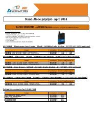
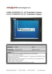
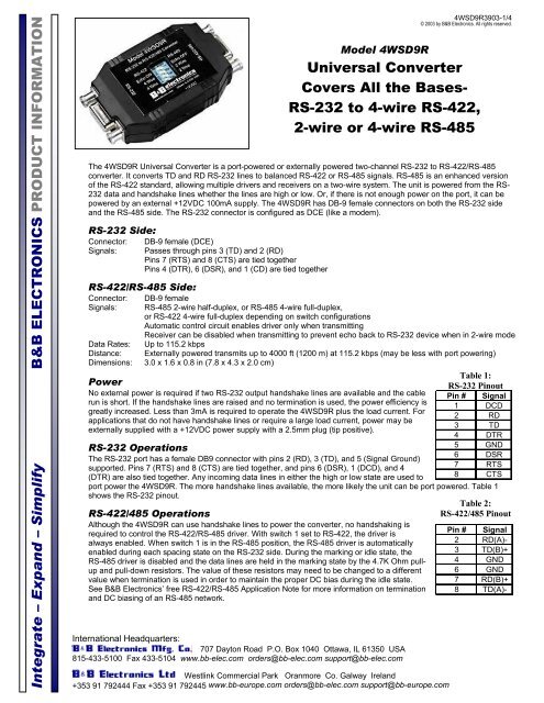
Integrate – Expand – Simplify B&B ELECTRONICS PRODUCT INFORMATIONInternational Headquarters:707 Dayton Road P.O. Box 1040 Ottawa, IL 61350 USA815-433-5100 Fax 433-5104 www.bb-elec.com orders@bb-elec.com support@bb-elec.comWestlink Commercial Park Oranmore Co. Galway Ireland+353 91 792444 Fax +353 91 792445 www.bb-europe.com orders@bb-elec.com support@bb-europe.com<strong>4WSD9R</strong>3903-1/4© 2003 by B&B Electronics. All rights reserved.Model <strong>4WSD9R</strong><strong>Universal</strong> <strong>Converter</strong>Covers All the Bases-RS-232 to 4-wire RS-422,2-wire or 4-wire RS-485The <strong>4WSD9R</strong> <strong>Universal</strong> <strong>Converter</strong> is a port-powered or externally powered two-channel RS-232 to RS-422/RS-485converter. It converts TD and RD RS-232 lines to balanced RS-422 or RS-485 signals. RS-485 is an enhanced versionof the RS-422 standard, allowing multiple drivers and receivers on a two-wire system. The unit is powered from the RS-232 data and handshake lines whether the lines are high or low. Or, if there is not enough power on the port, it can bepowered by an external +12VDC 100mA supply. The <strong>4WSD9R</strong> has DB-9 female connectors on both the RS-232 sideand the RS-485 side. The RS-232 connector is configured as DCE (like a modem).RS-232 Side:Connector: DB-9 female (DCE)Signals: Passes through pins 3 (TD) and 2 (RD)Pins 7 (RTS) and 8 (CTS) are tied togetherPins 4 (DTR), 6 (DSR), and 1 (CD) are tied togetherRS-422/RS-485 Side:Connector: DB-9 femaleSignals: RS-485 2-wire half-duplex, or RS-485 4-wire full-duplex,or RS-422 4-wire full-duplex depending on switch configurationsAutomatic control circuit enables driver only when transmittingReceiver can be disabled when transmitting to prevent echo back to RS-232 device when in 2-wire modeData Rates: Up to 115.2 kbpsDistance: Externally powered transmits up to 4000 ft (1200 m) at 115.2 kbps (may be less with port powering)Dimensions: 3.0 x 1.6 x 0.8 in (7.8 x 4.3 x 2.0 cm)PowerNo external power is required if two RS-232 output handshake lines are available and the cablerun is short. If the handshake lines are raised and no termination is used, the power efficiency isgreatly increased. Less than 3mA is required to operate the <strong>4WSD9R</strong> plus the load current. Forapplications that do not have handshake lines or require a large load current, power may beexternally supplied with a +12VDC power supply with a 2.5mm plug (tip positive).Table 1:RS-232 PinoutPin # Signal1 DCD2 RD3 TD4 DTR5 GND6 DSR7 RTS8 CTSRS-232 OperationsThe RS-232 port has a female DB9 connector with pins 2 (RD), 3 (TD), and 5 (Signal Ground)supported. Pins 7 (RTS) and 8 (CTS) are tied together, and pins 6 (DSR), 1 (DCD), and 4(DTR) are also tied together. Any incoming data lines in either the high or low state are used toport power the <strong>4WSD9R</strong>. The more handshake lines available, the more likely the unit can be port powered. Table 1shows the RS-232 pinout.RS-422/485 OperationsAlthough the <strong>4WSD9R</strong> can use handshake lines to power the converter, no handshaking isrequired to control the RS-422/RS-485 driver. With switch 1 set to RS-422, the driver isalways enabled. When switch 1 is in the RS-485 position, the RS-485 driver is automaticallyenabled during each spacing state on the RS-232 side. During the marking or idle state, theRS-485 driver is disabled and the data lines are held in the marking state by the 4.7K Ohm pullupand pull-down resistors. The value of these resistors may need to be changed to a differentvalue when termination is used in order to maintain the proper DC bias during the idle state.See B&B Electronics’ free RS-422/RS-485 Application Note for more information on terminationand DC biasing of an RS-485 network.Table 2:RS-422/485 PinoutPin # Signal2 RD(A)-3 TD(B)+4 GND6 GND7 RD(B)+8 TD(A)-
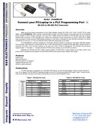
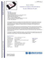
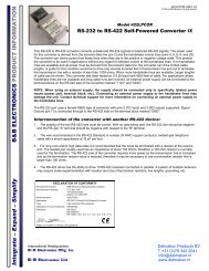
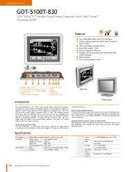
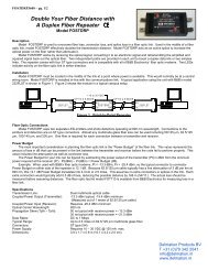
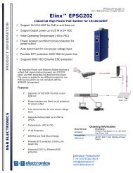
Integrate – Expand – Simplify B&B ELECTRONICS PRODUCT INFORMATIONRS-485 2-Wire Half-DuplexThis communications mode is used to connect several RS-485 devices to the samenetwork with a minimum number of wires when only one unit talks at a time. The RS-485driver is automatically enabled during each spacing state on the RS-232 side. During themarking or idle state, the RS-485 driver is disabled and the data lines are held in themarking state by the 4.7K Ohm pull-up and pull-down resistors. The value of theseresistors may need to be changed to a different value when termination is used in orderto maintain the proper DC bias during the idle state.International Headquarters:707 Dayton Road P.O. Box 1040 Ottawa, IL 61350 USA815-433-5100 Fax 433-5104 www.bb-elec.com orders@bb-elec.com support@bb-elec.comWestlink Commercial Park Oranmore Co. Galway Ireland+353 91 792444 Fax +353 91 792445 www.bb-europe.com orders@bb-elec.com support@bb-europe.com<strong>4WSD9R</strong>3903-2/4© 2003 by B&B Electronics. All rights reserved.Table 3: Switch settings forRS-485 2-wire half-duplexSwitch #Position1 RS-4852 Echo Off3 2-wire4 2-wireSee B&B Electronics’ free RS-422/RS-485 Application Note for more information ontermination and DC biasing of an RS-485 network. To set up for this mode on the <strong>4WSD9R</strong>, place switch 1 in the RS-485 position, switch 2 in the echo off position, and switches 3 and 4 in the 2-wire position. Follow the wiring diagramin Figure1 to connect to a 2-wire half-duplex network.9-pin M/F cableFigure 1: RS-485 2-wire half-duplex diagramRS-485 4-Wire Full-DuplexThis communications mode is typically one of the slaves in a master/slave RS-485setup. The RS-485 driver is automatically enabled during each spacing state on theRS-232 side. During the marking or idle state, the RS-485 driver is disabled and thedata lines are held in the marking state by the 4.7K Ohm pull-up and pull-downresistors. The value of these resistors may need to be changed to a different valuewhen termination is used in order to maintain the proper DC bias during the idle state.See B&B Electronics’ free RS-422/RS-485 Application Note for more information ontermination and DC biasing of an RS-485 network.Table 4: Switch settings forRS-485 4-wire full-duplexSwitch # Position1 RS-4852 Echo ON3 4-wire4 4-wireThe receiver is enabled at all times, allowing devices to receive information even while they are respondingto a request. To set up for this mode on the <strong>4WSD9R</strong>, place switch 1 in the RS-485 position, switch 2 in theecho on position, and switches 3 and 4 in the 4-wire position. The wiring between the slave and the masteris identical to the RS-422 4-wire full-duplex diagram shown in Figure 3, and in many cases the master in amaster/slave RS-485 network is set up as an RS-422 device. When multiple slaves are on the samenetwork, the connection between the master and each slave must be the same as shown in Figure 2. Thiswill cause all slaves to have their transmitters connected and their receivers connected, and not allowcommunications between the slaves themselves.
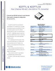
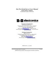
Integrate – Expand – Simplify B&B ELECTRONICS PRODUCT INFORMATION9-pin M/F cableFigure 2: RS-485 4-wire full-duplex diagramRS-422 4-Wire Full-Duplex:This communications mode is typically used for point-to-point communications over longdistances with better noise immunity than RS-232. Another common use would be as themaster in a master/slave configuration. The RS-422 driver and receiver are alwaysenabled to allow full-duplex communications. In order to do this there must be a pair ofwires dedicated to the driver, a pair dedicated to the receiver, and a ground referencewire i for a total of 5 lines to operate properly. To set up for this mode, put switch 1 in theRS-422 position, switch 2 in the Echo On position, and switches 3 and 4 in the 4-wireposition as shown in Table 5.9-pin M/F cableFigure 3: RS-422 4-wire full-duplex diagramInternational Headquarters:707 Dayton Road P.O. Box 1040 Ottawa, IL 61350 USA815-433-5100 Fax 433-5104 www.bb-elec.com orders@bb-elec.com support@bb-elec.comWestlink Commercial Park Oranmore Co. Galway Ireland+353 91 792444 Fax +353 91 792445 www.bb-europe.com orders@bb-elec.com support@bb-europe.com<strong>4WSD9R</strong>3903-3/4© 2003 by B&B Electronics. All rights reserved.Table 5: Switch settings forRS-422 4-wire full-duplexSwitch # Position1 RS-4222 Echo On3 4-wire4 4-wire_________________________i If you are concerned about creating ground loops by connecting grounds of units together, please check intoB&B Electronics’ line of optically isolated RS-232 to RS-422/485 units such as the 485OT9L.This product is Designed and Manufactured in the USA of domestic and imported components.
Integrate – Expand – Simplify B&B ELECTRONICS PRODUCT INFORMATIONDECLARATION OF CONFORMITYManufacturer’s Name:B&B Electronics Manufacturing CompanyManufacturer’s Address: P.O. Box 1040707 Dayton RoadOttawa, IL 61350 USAModel Number:<strong>4WSD9R</strong>Description:RS-422/485 <strong>Converter</strong>Type:Light industrial ITE equipmentApplication of Council Directive: 89/336/EECStandards: EN 55022EN 61000-6-1EN 61000 (-4-2, -4-3, -4-4, -4-5, -4-6, -4-8, -4-11)William H. Franklin III, Director of EngineeringInternational Headquarters:707 Dayton Road P.O. Box 1040 Ottawa, IL 61350 USA815-433-5100 Fax 433-5104 www.bb-elec.com orders@bb-elec.com support@bb-elec.comWestlink Commercial Park Oranmore Co. Galway Ireland+353 91 792444 Fax +353 91 792445 www.bb-europe.com orders@bb-elec.com support@bb-europe.com<strong>4WSD9R</strong>3903-4/4© 2003 by B&B Electronics. All rights reserved.