4WSD9R - Datasheet - Universal Converter - Delmation
4WSD9R - Datasheet - Universal Converter - Delmation
4WSD9R - Datasheet - Universal Converter - Delmation

Create successful ePaper yourself
Turn your PDF publications into a flip-book with our unique Google optimized e-Paper software.
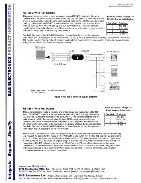
Integrate – Expand – Simplify B&B ELECTRONICS PRODUCT INFORMATIONRS-485 2-Wire Half-DuplexThis communications mode is used to connect several RS-485 devices to the samenetwork with a minimum number of wires when only one unit talks at a time. The RS-485driver is automatically enabled during each spacing state on the RS-232 side. During themarking or idle state, the RS-485 driver is disabled and the data lines are held in themarking state by the 4.7K Ohm pull-up and pull-down resistors. The value of theseresistors may need to be changed to a different value when termination is used in orderto maintain the proper DC bias during the idle state.International Headquarters:707 Dayton Road P.O. Box 1040 Ottawa, IL 61350 USA815-433-5100 Fax 433-5104 www.bb-elec.com orders@bb-elec.com support@bb-elec.comWestlink Commercial Park Oranmore Co. Galway Ireland+353 91 792444 Fax +353 91 792445 www.bb-europe.com orders@bb-elec.com support@bb-europe.com<strong>4WSD9R</strong>3903-2/4© 2003 by B&B Electronics. All rights reserved.Table 3: Switch settings forRS-485 2-wire half-duplexSwitch #Position1 RS-4852 Echo Off3 2-wire4 2-wireSee B&B Electronics’ free RS-422/RS-485 Application Note for more information ontermination and DC biasing of an RS-485 network. To set up for this mode on the <strong>4WSD9R</strong>, place switch 1 in the RS-485 position, switch 2 in the echo off position, and switches 3 and 4 in the 2-wire position. Follow the wiring diagramin Figure1 to connect to a 2-wire half-duplex network.9-pin M/F cableFigure 1: RS-485 2-wire half-duplex diagramRS-485 4-Wire Full-DuplexThis communications mode is typically one of the slaves in a master/slave RS-485setup. The RS-485 driver is automatically enabled during each spacing state on theRS-232 side. During the marking or idle state, the RS-485 driver is disabled and thedata lines are held in the marking state by the 4.7K Ohm pull-up and pull-downresistors. The value of these resistors may need to be changed to a different valuewhen termination is used in order to maintain the proper DC bias during the idle state.See B&B Electronics’ free RS-422/RS-485 Application Note for more information ontermination and DC biasing of an RS-485 network.Table 4: Switch settings forRS-485 4-wire full-duplexSwitch # Position1 RS-4852 Echo ON3 4-wire4 4-wireThe receiver is enabled at all times, allowing devices to receive information even while they are respondingto a request. To set up for this mode on the <strong>4WSD9R</strong>, place switch 1 in the RS-485 position, switch 2 in theecho on position, and switches 3 and 4 in the 4-wire position. The wiring between the slave and the masteris identical to the RS-422 4-wire full-duplex diagram shown in Figure 3, and in many cases the master in amaster/slave RS-485 network is set up as an RS-422 device. When multiple slaves are on the samenetwork, the connection between the master and each slave must be the same as shown in Figure 2. Thiswill cause all slaves to have their transmitters connected and their receivers connected, and not allowcommunications between the slaves themselves.