ESP901, ESP901E - Manual - One Port Serial Server ... - Delmation
ESP901, ESP901E - Manual - One Port Serial Server ... - Delmation
ESP901, ESP901E - Manual - One Port Serial Server ... - Delmation

You also want an ePaper? Increase the reach of your titles
YUMPU automatically turns print PDFs into web optimized ePapers that Google loves.
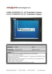
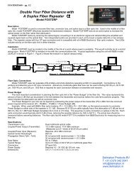
<strong>One</strong> <strong>Port</strong> <strong>Serial</strong> <strong>Server</strong> Users <strong>Manual</strong>Model <strong>ESP901</strong>, <strong>ESP901</strong>EDocumentation Number: <strong>ESP901</strong>-2303International HeadquartersB&B Electronics Mfg. Co. Inc.707 Dayton Road -- P.O. Box 1040 -- Ottawa, IL 61350 USAPhone (815) 433-5100 -- General Fax (815) 433-5105Home Page: www.bb-elec.comSales e-mail: orders@bb-elec.com -- Fax (815) 433-5109Technical Support e-mail: support@bb.elec.com -- Fax (815) 433-5104European HeadquartersB&B Electronics Ltd.Westlink Commercial Park, Oranmore, Co. Galway, IrelandPhone +353 91-792444 -- Fax +353 91-792445Home Page: www.bb-europe.comSales e-mail: sales@bb-europe.comTechnical Support e-mail: support@bb-europe.comB&B Electronics – June 2003Documentation Number: <strong>ESP901</strong>-2303 <strong>Manual</strong>Title PageB&B Electronics Mfg Co Inc – 707 Dayton Rd - PO Box 1040 - Ottawa IL 61350 - Ph 815-433-5100 - Fax 815-433-5104B&B Electronics Ltd – Westlink Commercial Park – Oranmore, Galway, Ireland – Ph +353 91-792444 – Fax +353 91-792445
Table of Contents1 Introduction..................................................................................... 1Features............................................................................................................ 1Product Specifications .................................................................................... 2Protocol............................................................................................................ 2Management .................................................................................................... 2Power & Environment.................................................................................... 2Default Settings ............................................................................................... 32 Making the Hardware Connections................................................ 4<strong>Serial</strong> Connection............................................................................................ 4Power Connection ........................................................................................... 4Ethernet Connection....................................................................................... 4Reset Button .................................................................................................... 4LED .................................................................................................................. 4Dip Switch Setting........................................................................................... 5Console......................................................................................................... 5Upgrade........................................................................................................ 5Default Setting............................................................................................. 5IP - RS232 Bridge........................................................................................ 6IP - RS422 Bridge........................................................................................ 6IP - RS485 Bridge........................................................................................ 6RS-485 Bias Resistors ................................................................................. 63 Vlinx <strong>ESP901</strong> Software Installation............................................... 84 Quick Start Using Management Software.................................... 12Searching LAN for <strong>ESP901</strong>.......................................................................... 12Configuration Screen.................................................................................... 13Setting the IP address, Netmask, and Gateway fields................................ 14Configuring the serial port settings............................................................. 15Configuring the mode of operation ............................................................. 15Setting TCP/UDP protocol ........................................................................... 16TCP/UDP <strong>Port</strong>............................................................................................... 16Remote IP address ........................................................................................ 16Saving the changes ........................................................................................ 165 Installing Virtual COM <strong>Port</strong>......................................................... 17Installing Virtual COM <strong>Port</strong> ........................................................................... 176 Setup Menu.................................................................................... 20Documentation Number: <strong>ESP901</strong>-2303 <strong>Manual</strong>B&B Electronics Mfg Co Inc – 707 Dayton Rd - PO Box 1040 - Ottawa IL 61350 - Ph 815-433-5100 - Fax 815-433-5104B&B Electronics Ltd – Westlink Commercial Park – Oranmore, Galway, Ireland – Ph +353 91-792444 – Fax +353 91-792445i
7 Console Mode Setup...................................................................... 238 Communication Modes ................................................................. 25Direct IP mode............................................................................................... 25Virtual COM mode....................................................................................... 25Paired mode................................................................................................... 26Heart Beat ....................................................................................................... 269 Configuring Virtual COM <strong>Port</strong> .................................................... 27Configuration with Management Software ................................................ 27Configuration with Device Manager ........................................................... 2810 Uninstalling the Virtual COM <strong>Port</strong>........................................... 30Removing the Virtual COM port with <strong>ESP901</strong> Management software ... 30Removal of the Virtual COM port using the Device Manager ................. 3111 Upgrade Mode............................................................................ 33<strong>Serial</strong> <strong>Port</strong> / Virtual COM............................................................................ 33iiDocumentation Number: <strong>ESP901</strong>-2303 <strong>Manual</strong>B&B Electronics Mfg Co Inc – 707 Dayton Rd - PO Box 1040 - Ottawa IL 61350 - Ph 815-433-5100 - Fax 815-433-5104B&B Electronics Ltd – Westlink Commercial Park – Oranmore, Galway, Ireland – Ph +353 91-792444 – Fax +353 91-792445
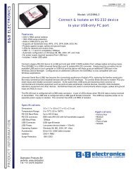
1 IntroductionThe Vlinx model <strong>ESP901</strong>Ethernet serial server connects RS-232, 422, 485 serialdevices to an Ethernet LAN/WAN providing a reliable communication connection.Existing Windows based serial software using standard Windows API does not haveto be modified to communicate over an Ethernet LAN to a serial device. The Vlinxvirtual COM port will make this an easy transition.The <strong>ESP901</strong> operates in “Direct IP Mode”, “Virtual COM Mode”, and “PairedMode”. The <strong>ESP901</strong> has one asynchronous DB-9 serial port and one 10/100 MbpsEthernet RJ-45 connection. The Ethernet port will auto-select 10BaseT or100BaseTX.The <strong>ESP901</strong> Windows driver installs a virtual COM port in the Device Manager ofthe operating system. The virtual COM port is designed to establish a connection withthe <strong>ESP901</strong>. This in turn will allow communications with the connected serial devicein the same manner as a device connected to the COM port on a PC. The LANbecomes transparent to the serial device and the software running on the PC.The <strong>ESP901</strong> can be configured as a TCP or UDP Client/<strong>Server</strong>. In direct IP andvirtual COM modes, <strong>ESP901</strong> should be configured as a server. <strong>ESP901</strong> also offers aHeart Beat feature to insure a reliable communications connection.FeaturesDIN rail or Panel mountSupports 10/100 Mbps EthernetSupports RS-232, RS-422, and RS-485 serial interfaceSupports LAN and WAN communicationsIn <strong>Server</strong> mode supports individual client sessions for security.Management access password protected.Virtual COM drivers for Window NT/98/ME/2000/XPDocumentation Number: <strong>ESP901</strong>-2303 <strong>Manual</strong> 1B&B Electronics Mfg Co Inc – 707 Dayton Rd - PO Box 1040 - Ottawa IL 61350 - Ph 815-433-5100 - Fax 815-433-5104B&B Electronics Ltd – Westlink Commercial Park – Oranmore, Galway, Ireland – Ph +353 91-792444 – Fax +353 91-792445
Product SpecificationsProtocolManagement<strong>Serial</strong> Memory:<strong>Serial</strong> Connection:Interface:<strong>Serial</strong>:64K bytesDTE – BD-9 male<strong>One</strong>-RS-232, RS-422, OR RS-485Dip Switch SelectableLAN: 10/100 Mbps Auto-detecting – 10 Base T,Supported Signals:Data Rate:Parity:Data Bits: 7, 8Stop Bits: 1, 2100 Base TXRS-232 - TX, RX, RTS, CTS, DTR, DSR,DCD, GNDRS-422 – TX+, TX-, RX+, RX-, RTS+, RTS-, CTS+, CTS-, GNDRS-485 - Data +, Data –110 bps to 230.4 k bpsnone, even, oddTCP, IP, ARP, DHCP, Telnet, HTTP, UDP, ICMPVlinx Manager, <strong>Serial</strong> Console, Telnet(Soon to be released Web server)Firmware upgradeablePower & EnvironmentPower Requirements:Operating Temperature:Storage Temperature:Humidity:Approvals:12 VDC @ 200 mA0 to 50 °C (32 to 122 °F)-20 to 60 °C (-4 to 140 °F)0 – 90% Non-CondensingCE, FCCDimensions: 3.35 x 4.5 x 0.90 in (8.5 x 11.5 x 2.3 cm)2 Documentation Number: <strong>ESP901</strong>-2303 <strong>Manual</strong>B&B Electronics Mfg Co Inc – 707 Dayton Rd - PO Box 1040 - Ottawa IL 61350 - Ph 815-433-5100 - Fax 815-433-5104B&B Electronics Ltd – Westlink Commercial Park – Oranmore, Galway, Ireland – Ph +353 91-792444 – Fax +353 91-792445
<strong>ESP901</strong> Default Settings<strong>Server</strong> Name:<strong>ESP901</strong><strong>Serial</strong> Number:Password:BlankDHCP:DisableIP Address: 192.168.0.1Net Mask: 255.255.255.0Gateway : 192.168.0.254Baud Rate: 9600Data/Parity/Stop: 8-N-1Flow Control:NoneTCP/UDP <strong>Port</strong>: TCP 4000Connection Mode: <strong>Server</strong>Remote IP Address: 255.255.255.255Documentation Number: <strong>ESP901</strong>-2303 <strong>Manual</strong> 3B&B Electronics Mfg Co Inc – 707 Dayton Rd - PO Box 1040 - Ottawa IL 61350 - Ph 815-433-5100 - Fax 815-433-5104B&B Electronics Ltd – Westlink Commercial Park – Oranmore, Galway, Ireland – Ph +353 91-792444 – Fax +353 91-792445
2 Making the Hardware ConnectionsThe following information is provided to give the user an understanding of how toconnect the <strong>ESP901</strong> to the LAN and serial device. A review of the switch settings andthe functionality of the LED’s are also provided.<strong>Serial</strong> ConnectionThe <strong>ESP901</strong> has a DB-9 male connector. The serial port is configured as a DTE (dataterminal equipment) device. All PC COM ports are DTE ports. A null modem cable isrequired to make a connection between the COM port on a PC and the <strong>ESP901</strong> serialport. A straight through cable is required to connect the <strong>ESP901</strong> serial port to a DCEdevice.Power ConnectionThe <strong>ESP901</strong> is shipped with a 12 VDC 500mA power supply. The tip of the connectoris positive. When inserted into the jack the red power light will illuminate confirmingpower has been supplied to the unit.Ethernet ConnectionA straight-through Ethernet cable can be used to connect the serial server to anEthernet hub, switch, or wall plate. A crossover Ethernet cable can be used to make aconnection directly to the NIC (Network Interface Card) on a PC or laptop.Reset ButtonThe reset button can be found between the switch and power jack. To reset the unitmanually apply power, insert a small plastic tool, and press lightly depressing switch.Hold for 3 seconds and release. The Link and Ready light will go out and turn backon.LED DefinitionLed NamePowerLinkReadyLed FunctionRed - Power has been suppliedGreen – 100 BaseTX Ethernet connection establishedYellow – 10 BaseT Ethernet connection establishedFlashing Green – system is ready4 Documentation Number: <strong>ESP901</strong>-2303 <strong>Manual</strong>B&B Electronics Mfg Co Inc – 707 Dayton Rd - PO Box 1040 - Ottawa IL 61350 - Ph 815-433-5100 - Fax 815-433-5104B&B Electronics Ltd – Westlink Commercial Park – Oranmore, Galway, Ireland – Ph +353 91-792444 – Fax +353 91-792445
Dip Switch SettingsThere are 6 operation modes defined by the 3 switches. They are defined in thefollowing table.Console ModeSw1 Sw2 Sw3 ModeOn On On ConsoleOff On On UpgradeOn Off On DefaultOff On Off RS-232On Off Off RS-422Off Off Off RS-485The console mode allows access to the <strong>ESP901</strong> setup menu. This is one way toreconfigure the default settings for the application. A serial connection is madebetween a COM port on the PC and the serial port of the <strong>ESP901</strong> with a null modemcable. In console mode, the serial port defaults to an RS-232 interface.The <strong>ESP901</strong> serial port default settings are, baud rate 9600, 8 data bits, no parity, and1 stop bit. Hyper Terminal should be used for this type of setup. Hyper Terminal’sserial settings are configured the same as the mentioned default settings of the <strong>ESP901</strong>and must be set to VT100 emulation mode. The default settings are used only if theyhave not been changed.See Chapter 7 for details.UpgradeThe newest firmware can be installed on the <strong>ESP901</strong> using the PC’s serial port or theVirtual COM port. Some firmware upgrades may require a new software upgrade withthe Virtual COM driver being the critical component.See Chapter 11 for details.Default SettingWhen the switches are set to this mode the <strong>ESP901</strong> will reset to the original defaultsettings.Documentation Number: <strong>ESP901</strong>-2303 <strong>Manual</strong> 5B&B Electronics Mfg Co Inc – 707 Dayton Rd - PO Box 1040 - Ottawa IL 61350 - Ph 815-433-5100 - Fax 815-433-5104B&B Electronics Ltd – Westlink Commercial Park – Oranmore, Galway, Ireland – Ph +353 91-792444 – Fax +353 91-792445
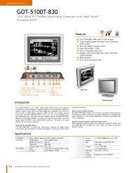
RS-232 InterfaceThe RS-232 supports 8 channels plus Signal Ground and is configured as DTE like acomputer. Signals are single ended and referenced to Ground. To used handshaking,Flow Control must be set to RTS/CTS during Configuration. Refer to the Pin outtable for connections.RS-422 InterfaceThe RS-422 mode supports 4 channels with full duplex operation for Receive,Transmit, RTS (Request To Send) and CTS (Clear To Send). The data lines are indifferential pairs with the B lines positive relative to the A lines. Ground provides acommon mode reference. To use handshaking Flow Control must be set to RTS/CTSduring configuration. Refer to the Pin out table for connections.RS-485 InterfaceThe RS-485 mode supports the Transmit and Receive Channels using 2-wire halfduplexoperation. The data lines are differential with the Data B line positive relativeto Data A in the Mark state. Ground provides a common mode reference. Refer tothe Pin out table for connections.Internal Setting To Select RS-485 BiasYou can select RS-485 Receiver Biasing from the <strong>ESP901</strong> if your network doesn’tsupply any. Remove the two side cover screws, slide the cover off, and then set thetwo bias jumpers (shown open) to enable biasing (shorting).6 Documentation Number: <strong>ESP901</strong>-2303 <strong>Manual</strong>B&B Electronics Mfg Co Inc – 707 Dayton Rd - PO Box 1040 - Ottawa IL 61350 - Ph 815-433-5100 - Fax 815-433-5104B&B Electronics Ltd – Westlink Commercial Park – Oranmore, Galway, Ireland – Ph +353 91-792444 – Fax +353 91-792445
DB9 Pin ConfigurationPin RS-232 RS-422 RS-4851 DCD RXDA (-)2 RXD RXDB (+)3 TXD TXDB (+) DATA B (+)4 DTR TXDA (-) DATA A (-)5 GND GND GND6 DSR CTSA (-)7 RTS CTSB (+)8 CTS RTSB (+)9 RI RTSA (-)Documentation Number: <strong>ESP901</strong>-2303 <strong>Manual</strong> 7B&B Electronics Mfg Co Inc – 707 Dayton Rd - PO Box 1040 - Ottawa IL 61350 - Ph 815-433-5100 - Fax 815-433-5104B&B Electronics Ltd – Westlink Commercial Park – Oranmore, Galway, Ireland – Ph +353 91-792444 – Fax +353 91-792445
3 Vlinx <strong>ESP901</strong> Software InstallationIt is recommended the user install the Management software and do a search for all<strong>ESP901</strong>’s connected to the LAN. When this is completed a window will list thedevices making them available for configuration.Configuring the serial server to meet your LAN and application requirement is an easyprocess with the available setup menu in the management software.The following procedure installs the Vlinx’s <strong>ESP901</strong> management software.1. Inserting the Vlinx CD in the CD-ROM will automatically launch the InstallShield Wizard.To manually start the software installation, select the Start button on thedesktop. At the Run command line type D:start.exe Then select OK. The D:is the drive letter for the CD Rom.2. The Install Shield Wizard window automatically displays to begin the setupprocedure.8 Documentation Number: <strong>ESP901</strong>-2303 <strong>Manual</strong>B&B Electronics Mfg Co Inc – 707 Dayton Rd - PO Box 1040 - Ottawa IL 61350 - Ph 815-433-5100 - Fax 815-433-5104B&B Electronics Ltd – Westlink Commercial Park – Oranmore, Galway, Ireland – Ph +353 91-792444 – Fax +353 91-792445
3. Select Next when the <strong>ESP901</strong> Setup window appears.4. In the Choose Destination Location window select Next to install themanager software in the default location. Select Browse to install into a userselected directory.Documentation Number: <strong>ESP901</strong>-2303 <strong>Manual</strong> 9B&B Electronics Mfg Co Inc – 707 Dayton Rd - PO Box 1040 - Ottawa IL 61350 - Ph 815-433-5100 - Fax 815-433-5104B&B Electronics Ltd – Westlink Commercial Park – Oranmore, Galway, Ireland – Ph +353 91-792444 – Fax +353 91-792445
5. The Setup Status window displays the progress of the installation.6. Select Finish when the Install Shield Wizard Complete screen appears.10 Documentation Number: <strong>ESP901</strong>-2303 <strong>Manual</strong>B&B Electronics Mfg Co Inc – 707 Dayton Rd - PO Box 1040 - Ottawa IL 61350 - Ph 815-433-5100 - Fax 815-433-5104B&B Electronics Ltd – Westlink Commercial Park – Oranmore, Galway, Ireland – Ph +353 91-792444 – Fax +353 91-792445
When the installation is complete the Install window closes allowing the user toaccess the management software in the program files. If loaded in the default locationGo to Start/Programs/B&B Electronics/Vlinx/ESP <strong>Server</strong>/ Vlinx ESP Manager toopen.Connect the <strong>ESP901</strong> to the LAN and apply power. The red LED indicates power hasbeen applied; the Link LED indicates an Ethernet connection has been made; and theReady LED will flash indicating communications with the unit can begin.Documentation Number: <strong>ESP901</strong>-2303 <strong>Manual</strong> 11B&B Electronics Mfg Co Inc – 707 Dayton Rd - PO Box 1040 - Ottawa IL 61350 - Ph 815-433-5100 - Fax 815-433-5104B&B Electronics Ltd – Westlink Commercial Park – Oranmore, Galway, Ireland – Ph +353 91-792444 – Fax +353 91-792445
4 Quick Start Using Management SoftwareThe manager software performs several functions, Uninstall Virtual COM port,Searching LAN for <strong>ESP901</strong>, Configure <strong>ESP901</strong>, Configure Virtual COM <strong>Port</strong>, andupgrade Firmware.Connect the <strong>ESP901</strong> to the LAN and apply power. The red LED indicates power hasbeen applied, the Link LED indicates an Ethernet connection has been made, and theReady LED will flash indicating communications with the unit can begin. See section2 for Hardware Connections.Once the <strong>ESP901</strong> is connected to the LAN the management software will be able tosearch the LAN for all connected <strong>ESP901</strong> servers and will display them in a windowby name and IP address.Searching LAN for <strong>ESP901</strong>1. Select <strong>ESP901</strong> Manager in the program file menu. If the default location wasselected during the installation the program will be found underStart/Programs/B&B Electronics/Vlinx/ESP <strong>Server</strong>. Select VLINX ESPManager.12 Documentation Number: <strong>ESP901</strong>-2303 <strong>Manual</strong>B&B Electronics Mfg Co Inc – 707 Dayton Rd - PO Box 1040 - Ottawa IL 61350 - Ph 815-433-5100 - Fax 815-433-5104B&B Electronics Ltd – Westlink Commercial Park – Oranmore, Galway, Ireland – Ph +353 91-792444 – Fax +353 91-792445
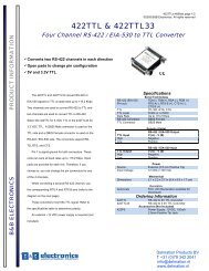
2. On the menu side bar select Searching <strong>ESP901</strong> button. The Searching for<strong>ESP901</strong> window opens and all <strong>ESP901</strong> serial servers connected on the LANare listed in the Manager Window.Configuration ScreenHighlight the serial server in the Manager Window and double click to open theconfiguration menu options.Documentation Number: <strong>ESP901</strong>-2303 <strong>Manual</strong> 13B&B Electronics Mfg Co Inc – 707 Dayton Rd - PO Box 1040 - Ottawa IL 61350 - Ph 815-433-5100 - Fax 815-433-5104B&B Electronics Ltd – Westlink Commercial Park – Oranmore, Galway, Ireland – Ph +353 91-792444 – Fax +353 91-792445
From the <strong>Server</strong> Properties menu the serial server IP address, Net Mask,Gateway, serial port settings and operation mode can be programmed into theunit. Select update and restart the <strong>ESP901</strong> once all settings are changed toconform to the desired application.Details on Menu settings can be found in Chapter 6.Setting the IP Address, Netmask, and Gateway FieldsIt is recommended to use a static IP address. The most commonly used option is tocontact the network administrator and request a static IP address. The administratorwill also have the Netmask and Gateway address information.Select the tab button to move to the next adjustable field in the menu. The arrow keyswill scroll the option available in each field.Start by tabbing to the IP address field and insert the new IP address. Follow the sameprocedure with the Netmask and Gateway fields. All three fields will have to conformto your LAN for proper operation.14 Documentation Number: <strong>ESP901</strong>-2303 <strong>Manual</strong>B&B Electronics Mfg Co Inc – 707 Dayton Rd - PO Box 1040 - Ottawa IL 61350 - Ph 815-433-5100 - Fax 815-433-5104B&B Electronics Ltd – Westlink Commercial Park – Oranmore, Galway, Ireland – Ph +353 91-792444 – Fax +353 91-792445
Configuring the <strong>Serial</strong> <strong>Port</strong> SettingsUse the Tab key to advance to the baud rate, Data/Parity/Stop bits, and Flowcontrol section of the menu. Use the arrow keys to advance to a selection thatmatches the connected serial device. The serial port settings must match theconnected serial device when using TCP/UDP socket programs. If the ESPVirtual COM driver is used the application software will control the <strong>ESP901</strong>serial port setting.Configuring the Mode of OperationIt must first be decided what Operation Mode is going to fit the application.Connection mode has 2 options, client and server.• When using the Virtual COM port feature select <strong>Server</strong>• When using socket software select <strong>Server</strong>• When using paired connection mode set one to server and one toclient.For more details see section 8, Communication Modes.Documentation Number: <strong>ESP901</strong>-2303 <strong>Manual</strong> 15B&B Electronics Mfg Co Inc – 707 Dayton Rd - PO Box 1040 - Ottawa IL 61350 - Ph 815-433-5100 - Fax 815-433-5104B&B Electronics Ltd – Westlink Commercial Park – Oranmore, Galway, Ireland – Ph +353 91-792444 – Fax +353 91-792445
Setting TCP/UDP ProtocolThe most common protocol is TCP. The default setting is TCP and should not bechanged unless your application specifies a UDP protocol.TCP/UDP <strong>Port</strong>The default port number is 4000. The TCP/UDP <strong>Port</strong> defines a communicationport. In all modes of operating, Virtual COM, Direct IP, and Paired modes, boththe TCP/UDP Client and server port settings must match.As an example the Virtual COM default setting TCP/UDP <strong>Port</strong> # 4000. If the port# in the setup menu is changed to 4001 the Virtual COM TCP/UDP <strong>Port</strong> willhave to be changed to 4001.The change can be made in the Device Manager of the operating system or usingthe <strong>ESP901</strong> Manager software.Remote IP AddressThe default setting is 255.255.255.255. It is recommended not to change thissetting until the application has been tested and is communicating properly. Atthat point the address filtering feature of the <strong>ESP901</strong> can be activated. Refer tothe Menu Overview section for more details.Saving the ChangesTo save the changes select the update button.Reset the <strong>ESP901</strong>Close the menu16 Documentation Number: <strong>ESP901</strong>-2303 <strong>Manual</strong>B&B Electronics Mfg Co Inc – 707 Dayton Rd - PO Box 1040 - Ottawa IL 61350 - Ph 815-433-5100 - Fax 815-433-5104B&B Electronics Ltd – Westlink Commercial Park – Oranmore, Galway, Ireland – Ph +353 91-792444 – Fax +353 91-792445
5 Installing Virtual COM <strong>Port</strong>The Virtual COM <strong>Port</strong> feature allows Windows platform software using standardAPI calls to be used in an Ethernet application.Running the Install Virtual COM port software adds a COM <strong>Port</strong> in the DeviceManager of the operating system. The COM port will look like a standard COMport to Windows software used in most applications allowing the software toopen a connection with the serial port located anywhere on the LAN. When usingthe virtual COM port the <strong>ESP901</strong> is configured as a TCP or UDP <strong>Server</strong>.1. On the Desk Top select Start/Programs/B&B Electronics/Vlinx/ Vlinx<strong>Server</strong>/Install Virtual COM.2. The Install Virtual COM program will automatically search the LAN for allavailable <strong>ESP901</strong> serial servers and display them in the Found <strong>ESP901</strong>window. Highlight the desired serial server and select OK.Documentation Number: <strong>ESP901</strong>-2303 <strong>Manual</strong> 17B&B Electronics Mfg Co Inc – 707 Dayton Rd - PO Box 1040 - Ottawa IL 61350 - Ph 815-433-5100 - Fax 815-433-5104B&B Electronics Ltd – Westlink Commercial Park – Oranmore, Galway, Ireland – Ph +353 91-792444 – Fax +353 91-792445
3. When the COMInst window opens select COM port # to map the serialserver to. The default Flow Control setting is None. An RTS/CTS option isavailable if used by the application program and serial hardware. TheProtocol, IP Address, and <strong>Port</strong> Number will mirror the settings of theselected serial server.If any settings are changed in this part of the Virtual COM setup it will onlyaffect the settings in the operating system Device Manager. It will not changethe settings in the <strong>ESP901</strong>.The settings of the Virtual COM port in the Device Manager and the <strong>ESP901</strong>Configuration menu must match. If the settings do not, the softwareconnecting to the Virtual COM port will be unsuccessful in opening theCOM port. Highlight the desired COM port # and select OK.18 Documentation Number: <strong>ESP901</strong>-2303 <strong>Manual</strong>B&B Electronics Mfg Co Inc – 707 Dayton Rd - PO Box 1040 - Ottawa IL 61350 - Ph 815-433-5100 - Fax 815-433-5104B&B Electronics Ltd – Westlink Commercial Park – Oranmore, Galway, Ireland – Ph +353 91-792444 – Fax +353 91-792445
4. Note: Your PC may have hardware COM ports and devices such as Modemsloaded on COM’s 1, 2, 3, or 4. It is recommended that the Virtual COM portselected start on COM 5 or higher.In Windows XP a Hardware Installation window stating that the drivers havenot been tested by Microsoft may appear. Select “Continue Anyway” toproceed with the installation.5. To confirm installation, go to the Device Manager and select <strong>Port</strong>s (COM &LPT). The installed Virtual COM port will be displayed as ESP Vlinx COM#.Documentation Number: <strong>ESP901</strong>-2303 <strong>Manual</strong> 19B&B Electronics Mfg Co Inc – 707 Dayton Rd - PO Box 1040 - Ottawa IL 61350 - Ph 815-433-5100 - Fax 815-433-5104B&B Electronics Ltd – Westlink Commercial Park – Oranmore, Galway, Ireland – Ph +353 91-792444 – Fax +353 91-792445
6 Setup MenuThere are three ways to access the setup menu and program the <strong>ESP901</strong>, Managementsoftware, Console mode, and Telnet. The menu pictured above displays in the <strong>ESP901</strong>Management software setup screen.Instructions on how to move around the menu and change settings pertains to theManagement setup menu but are similar in Telnet.There are a few pre-defined keys to move around the menu and to save changes.Space Bar:TAB:Back Space:Arrow Keys:Enter:To refresh the configuration page.To move the cursor to next field.To move the cursor to previous field.To move the cursor around the configuration page.Telnet only - To open 2 nd window of selections, confirm a selectedchange, or to activate the save, default, reset and status.<strong>Server</strong> NameThe server name is user configurable. It is recommended users with more than one<strong>ESP901</strong> connected to the LAN assign a new name to each. When the Managersoftware searches for servers on the LAN it will display the server name allowing theuser to distinguish between <strong>ESP901</strong>’s.PasswordEntering a password activates a security feature on the serial server. Once a passwordis entered it will be required to access the menu and make changes.DHCPDHCP servers are a part of numerous LAN management systems. The DHCP fieldhas two selections, “Enable” or “Disable”. Arrow to the desired selection and selectenter.When enabled, <strong>ESP901</strong> will send a DHCP request to the DHCP server, which willassign a dynamic IP address, net mask, and gateway to the <strong>ESP901</strong>. If a DHCP serveris not available on the network the <strong>ESP901</strong> will time out after 10 seconds and thedefault values will remain.20 Documentation Number: <strong>ESP901</strong>-2303 <strong>Manual</strong>B&B Electronics Mfg Co Inc – 707 Dayton Rd - PO Box 1040 - Ottawa IL 61350 - Ph 815-433-5100 - Fax 815-433-5104B&B Electronics Ltd – Westlink Commercial Park – Oranmore, Galway, Ireland – Ph +353 91-792444 – Fax +353 91-792445
IP AddressA static IP address can also be assigned in this section of the menu. A dynamicaddress assigned by the DHCP server may change if the <strong>ESP901</strong> looses the Ethernetconnection or power is removed. The host (client) communication software requests aconnection to the specific IP address of the serial server. If the DHCP reassigns adifferent IP address the software will not be able to communicate with the hardware. Itis recommended to use a static IP address.A static IP address is permanent and will not change unless changed in the menu. Inmost cases the network administrator establishes the static address to be used.Net MaskThe default LAN net mask is configured for a Class C address. This maybereconfigured by the user.GatewayThe gateway IP address allows users to access the serial server from outside the LAN.MAC AddressThe MAC address is not adjustable. This is assigned in the factory. Every Ethernetdevice manufactured has it own unique MAC address.Link StatusLink status automatically displays the type of Ethernet connection. It will eitherdisplay 10 BaseT or 100BaseTX in full duplex or half duplex. This will depend on theLAN, switches, hubs used in the LAN topology.Baud RateThe serial port baud rate on the <strong>ESP901</strong> must match the serial baud rate of theconnected device unless using Virtual COM mode. In Virtual COM mode thesoftware program will establish serial settings. Use the arrow keys to change thesetting to the desired baud rate.Data/Parity/StopThis setting will have to match the data format of the connected device. Tab to theData/Parity/Stop field and arrow to the desired selection.Documentation Number: <strong>ESP901</strong>-2303 <strong>Manual</strong> 21B&B Electronics Mfg Co Inc – 707 Dayton Rd - PO Box 1040 - Ottawa IL 61350 - Ph 815-433-5100 - Fax 815-433-5104B&B Electronics Ltd – Westlink Commercial Park – Oranmore, Galway, Ireland – Ph +353 91-792444 – Fax +353 91-792445
Flow ControlThe flow control setting must match the connected serial device. Tab to the FlowControl field and arrow to None or RTS/CTS.TCP/UDP <strong>Port</strong>Tab to the first field and select TCP or UDP protocol. If the user’s application doesnot require a UDP connection it is recommended to use TCP. TCP guarantees reliablecommunication through the use of error checking.The second field chooses the port number of the connection. A predefined TCP port,5300, is reserved for the Heart Beat. See Chapter 4 for details on the Heart Beatfeature.Connection ModeThe Connection mode has two options, Client and <strong>Server</strong>. To setup Paired Mode two<strong>ESP901</strong> serial servers are required, with one setup as the server and the second setupas a client.A single <strong>ESP901</strong> is setup in the server mode to establish a Windows Virtual COMconnection or a raw TCP or UDP connection.Remote IP AddressThis is a security feature that is activated when the IP address of the desired client isprogrammed into the remote IP Address setting of the menu. This tells the <strong>ESP901</strong> tocommunicate with only the listed IP address and to filter out all other requests forconnection. The <strong>ESP901</strong> is setup in the menu as a TCP or UDP server to us thisfeature.There are five buttons at the bottom of the menu, “Save”, “Default”, “Running”,“Reset” and Status. The user can use TAB, Backspace, or arrow keys to move cursorto the button’s position, and then press enter. The “Save” action stores theconfiguration data to flash. The user must reset the device for the stored configurationdata to take effect. The “Default” button restores the editing configuration data todefault menu settings. The “Running” button restores the editing configuration datato the value that stored in the flash. For the edited value to take effect, user need tosave the configuration data, then reset the device. The Status button displays howmany Ethernet packets and serial bytes are transmitted and receive. A refresh button isavailable to update the displayed figures.22 Documentation Number: <strong>ESP901</strong>-2303 <strong>Manual</strong>B&B Electronics Mfg Co Inc – 707 Dayton Rd - PO Box 1040 - Ottawa IL 61350 - Ph 815-433-5100 - Fax 815-433-5104B&B Electronics Ltd – Westlink Commercial Park – Oranmore, Galway, Ireland – Ph +353 91-792444 – Fax +353 91-792445
7 Console Mode SetupBefore the <strong>ESP901</strong> is installed on a LAN the Console Mode can be used to change thedefault the settings. Connect a null modem cable between the serial port on the ES901and the COM port on the PC. Apply power to the <strong>ESP901</strong>. The power and ready LEDwill light.Using Hyper Terminal open the connected PC COM port at a baud rate of 9600, Databits 8, Parity None, Stop bits 1, and Flow control None.To view the menu hit the space bar. Use the arrow keys to select the desired field. Thefollowing fields have a selection table to choose from, DHCP, Baud Rate,Data/Parity/Stop, Flow control, TCP/UDP port and Connection mode. To view theoptions arrow to the field and select enter.Once all the changes have been made move to the Save field and select enter.Documentation Number: <strong>ESP901</strong>-2303 <strong>Manual</strong> 23B&B Electronics Mfg Co Inc – 707 Dayton Rd - PO Box 1040 - Ottawa IL 61350 - Ph 815-433-5100 - Fax 815-433-5104B&B Electronics Ltd – Westlink Commercial Park – Oranmore, Galway, Ireland – Ph +353 91-792444 – Fax +353 91-792445
The restart screen will appear. Select Yes to save changes. This is necessary to writethe settings to the server. To view the changes press the space bar. The screen willreappear.24 Documentation Number: <strong>ESP901</strong>-2303 <strong>Manual</strong>B&B Electronics Mfg Co Inc – 707 Dayton Rd - PO Box 1040 - Ottawa IL 61350 - Ph 815-433-5100 - Fax 815-433-5104B&B Electronics Ltd – Westlink Commercial Park – Oranmore, Galway, Ireland – Ph +353 91-792444 – Fax +353 91-792445
8 Communication ModesThe <strong>ESP901</strong> allows serial devices to communicate over a LAN or Intranet network.<strong>Serial</strong> devices are no longer limited to a physical connection to the PC COM port.They can be installed anywhere on the LAN using TCP/IP or UDP/IPcommunications. This will also allow traditional PC COM ports access to a serialdevice anywhere on the LAN network.Direct IP ModeDirect IP connections allow applications using TCP/IP or UDP/IP network socketprograms to communicate with the asynchronous serial port on the <strong>ESP901</strong>. In thistype of application the <strong>ESP901</strong> is configured to TCP or UDP server. The socketprogram running on the PC establishes a communication connection with the <strong>ESP901</strong>.The raw data is sent directly to and from the serial port.Virtual COM ModeThe Virtual COM mode requires the installation of a driver. When installed a newCOM port is added to the Device Manager. Windows programs using standardWindows API calls will be able to interface with Virtual ports. The PC will act as thehost connecting to the <strong>ESP901</strong> when the program opens the virtual COM port.Once the connection is made, the LAN is transparent to the serial device. Applicationswork just as if the serial device is connected a host’s physical COM port. The virtualCOM port converts the application’s data into IP packet destined for the <strong>ESP901</strong>,which in turn converts the IP packet back to serial data.In this mode, the <strong>ESP901</strong> must be set to either TCP/server or UDP/server in the menuwith a designated communication port number. The virtual COM driver is a TCP orUDP client.Documentation Number: <strong>ESP901</strong>-2303 <strong>Manual</strong> 25B&B Electronics Mfg Co Inc – 707 Dayton Rd - PO Box 1040 - Ottawa IL 61350 - Ph 815-433-5100 - Fax 815-433-5104B&B Electronics Ltd – Westlink Commercial Park – Oranmore, Galway, Ireland – Ph +353 91-792444 – Fax +353 91-792445
Paired Mode (<strong>Serial</strong> Tunneling)Paired mode is also called serial tunneling. When this type of configuration is selectedadditional software will not have to be loaded on a host PC. In fact a PC is notrequired to make the connection. Any two dumb serial devices that can communicatewith each other through a serial link will be able to communicate using two <strong>ESP901</strong>’sand the LAN.Two <strong>ESP901</strong>’s are configured with one setup as a TCP or UDP client and the other toTCP/UDP server. When setting up the <strong>Server</strong>, the Remote IP address section mustcontain the address of the Client. This will allow the Client’s IP address to pass the IPaddress-filtering feature of the <strong>Server</strong>. Conversely the Remote IP address of the Clientmust contain the <strong>Server</strong>s IP address.Heart BeatThe <strong>ESP901</strong> provides a convenient way to establish reliable communications betweentwo devices. Communication port 5300 is reserved for the Heartbeat Protocol.Without this feature a device that loses a connection and stops communicating wouldnot be able to reconnect without personally attending to the problem. A TCP dataconnection can be lost when there is a power failure or temporary loss of an Ethernetconnection on either the client or server.If a loss occurs the Heart Beat feature will try to reconnect the TCP data connectionevery 5 seconds until communications is established again. The Heart Beat feature isavailable to use with the Virtual COM port mode and TCP Direct IP connection. Thisis not available when using a UDP application.26 Documentation Number: <strong>ESP901</strong>-2303 <strong>Manual</strong>B&B Electronics Mfg Co Inc – 707 Dayton Rd - PO Box 1040 - Ottawa IL 61350 - Ph 815-433-5100 - Fax 815-433-5104B&B Electronics Ltd – Westlink Commercial Park – Oranmore, Galway, Ireland – Ph +353 91-792444 – Fax +353 91-792445
9 Configuring Virtual COM <strong>Port</strong>The Virtual COM port can be configured in the Device Manager of the operatingsystem or the Management software. In either case the IP Address, <strong>Port</strong> #,Protocol, and Flow Control settings must match the <strong>ESP901</strong> settings for thesoftware to open the Virtual COM port.Configuration with Management Software1. At the Desk Top select Start/Programs/B&B Electronics/Vlinx/ ESP Vlinx/ESP Manager. Double click the Virtual COM Configuration button.2. Double click the COM # displayed in the screen to open the configurationwindow.Documentation Number: <strong>ESP901</strong>-2303 <strong>Manual</strong> 27B&B Electronics Mfg Co Inc – 707 Dayton Rd - PO Box 1040 - Ottawa IL 61350 - Ph 815-433-5100 - Fax 815-433-5104B&B Electronics Ltd – Westlink Commercial Park – Oranmore, Galway, Ireland – Ph +353 91-792444 – Fax +353 91-792445
3. Make the adjustments and select OK to complete the changes.Configuration with Device Manager1. On the Desk Top select Start/Settings/Control Panel. Select the System Iconwhen the Control Panel window opens.2. In the System Properties window select the Device Manager button.(Windows XP window shown.)28 Documentation Number: <strong>ESP901</strong>-2303 <strong>Manual</strong>B&B Electronics Mfg Co Inc – 707 Dayton Rd - PO Box 1040 - Ottawa IL 61350 - Ph 815-433-5100 - Fax 815-433-5104B&B Electronics Ltd – Westlink Commercial Park – Oranmore, Galway, Ireland – Ph +353 91-792444 – Fax +353 91-792445
3. In the Device Manager select the + button next to <strong>Port</strong>s (COM & LPT) toexpand and see the Vlinx ESP (COM #). Double click Vlinx ESP (COM #)to open the Properties window.4. Select the Configuration tab. From here the same settings found in the<strong>ESP901</strong> Manager can be adjusted.Documentation Number: <strong>ESP901</strong>-2303 <strong>Manual</strong> 29B&B Electronics Mfg Co Inc – 707 Dayton Rd - PO Box 1040 - Ottawa IL 61350 - Ph 815-433-5100 - Fax 815-433-5104B&B Electronics Ltd – Westlink Commercial Park – Oranmore, Galway, Ireland – Ph +353 91-792444 – Fax +353 91-792445
10 Uninstalling the Virtual COM <strong>Port</strong>The <strong>ESP901</strong> Management software Uninstall Virtual Com port feature willremove the mapped COM port in the Device Manager of Windows 2000 and XPoperating systems. It may also be removed in the Device Manager of Windows98, ME, NT, 2000, and XP. Windows 98 users will also find a Remove VirtualCOM feature in the programs file.Removing the Virtual COM port with the <strong>ESP901</strong> Management Software1. At the Desk Top select Start/Programs/B&B Electronics/Vlinx/ ESPManager/Vlinx ESP Manager2. In the Manager window select Virtual COM Configuration. Highlight themapped COM port number to be removed.3. Select Uninstall Virtual COM button. The Manager will ask forconformation. Select OK to complete the uninstall procedure.30 Documentation Number: <strong>ESP901</strong>-2303 <strong>Manual</strong>B&B Electronics Mfg Co Inc – 707 Dayton Rd - PO Box 1040 - Ottawa IL 61350 - Ph 815-433-5100 - Fax 815-433-5104B&B Electronics Ltd – Westlink Commercial Park – Oranmore, Galway, Ireland – Ph +353 91-792444 – Fax +353 91-792445
Removing the Virtual COM <strong>Port</strong> using Device ManagerThe screen shots were taken from a Windows XP operating system1. On the Desktop select Start/Settings/Control Panel. Select the system iconwhen the manager window opens.Documentation Number: <strong>ESP901</strong>-2303 <strong>Manual</strong> 31B&B Electronics Mfg Co Inc – 707 Dayton Rd - PO Box 1040 - Ottawa IL 61350 - Ph 815-433-5100 - Fax 815-433-5104B&B Electronics Ltd – Westlink Commercial Park – Oranmore, Galway, Ireland – Ph +353 91-792444 – Fax +353 91-792445
2. Select Device Manager in the Systems Properties window. In the DeviceManger window select the + next to <strong>Port</strong>s (COM LPT) to expand.3. Highlight Vlinx ESP (COM #) to be removed, go the Action tab at the top ofwindow and select uninstall. A confirm Device Removal window willappear. Select OK to procedure.4. The <strong>ESP901</strong> COM # will be removed and the Device Manager window willrefresh and display the remaining COM ports.32 Documentation Number: <strong>ESP901</strong>-2303 <strong>Manual</strong>B&B Electronics Mfg Co Inc – 707 Dayton Rd - PO Box 1040 - Ottawa IL 61350 - Ph 815-433-5100 - Fax 815-433-5104B&B Electronics Ltd – Westlink Commercial Park – Oranmore, Galway, Ireland – Ph +353 91-792444 – Fax +353 91-792445
11 Upgrade ModeNew firmware may be available at times on our web site and may bedownloaded and flashed to the <strong>ESP901</strong> currently in use. The user can upgradeusing a direct connection to the <strong>ESP901</strong> serial port or the Virtual COM portfeature.<strong>Serial</strong> <strong>Port</strong> / Virtual COM1. Download the new upgrade .hex file and place in a folder.2. Set <strong>ESP901</strong> Dip Switches to Upgrade, Switch 1 off, Switch 2 on, and Switch3 on.3. Connect a null modem cable between the PC and the <strong>ESP901</strong>. When usingthe Virtual COM mode a cable is not required.4. Open the management software and select the Upgrade button. Forinstructions on accessing the management software refer to Section 4 QuickStart.5. In the <strong>Serial</strong> <strong>Port</strong> selection options select the COM port number used toconnect the PC to the <strong>ESP901</strong>. If using the Virtual COM port select thatnumber.6. Select Browse, find the location of the firmware, select Open, and then selectthe upgrade button.Documentation Number: <strong>ESP901</strong>-2303 <strong>Manual</strong> 33B&B Electronics Mfg Co Inc – 707 Dayton Rd - PO Box 1040 - Ottawa IL 61350 - Ph 815-433-5100 - Fax 815-433-5104B&B Electronics Ltd – Westlink Commercial Park – Oranmore, Galway, Ireland – Ph +353 91-792444 – Fax +353 91-792445
7. A serial menu will appear allowing the upgrade software to be setup the sameas the <strong>ESP901</strong> serial settings. The settings must match or the upgrade willfail.34 Documentation Number: <strong>ESP901</strong>-2303 <strong>Manual</strong>B&B Electronics Mfg Co Inc – 707 Dayton Rd - PO Box 1040 - Ottawa IL 61350 - Ph 815-433-5100 - Fax 815-433-5104B&B Electronics Ltd – Westlink Commercial Park – Oranmore, Galway, Ireland – Ph +353 91-792444 – Fax +353 91-792445
8. A window showing the Upgrade progress will appear followed by a windowindicating the Upgrade was successful. Select and exit from the Managersoftware.9. Reset <strong>ESP901</strong> by using the Reset Button on unit, the management software,or telnet. This will complete the upgrade process.Documentation Number: <strong>ESP901</strong>-2303 <strong>Manual</strong> 35B&B Electronics Mfg Co Inc – 707 Dayton Rd - PO Box 1040 - Ottawa IL 61350 - Ph 815-433-5100 - Fax 815-433-5104B&B Electronics Ltd – Westlink Commercial Park – Oranmore, Galway, Ireland – Ph +353 91-792444 – Fax +353 91-792445
36 Documentation Number: <strong>ESP901</strong>-2303 <strong>Manual</strong>B&B Electronics Mfg Co Inc – 707 Dayton Rd - PO Box 1040 - Ottawa IL 61350 - Ph 815-433-5100 - Fax 815-433-5104B&B Electronics Ltd – Westlink Commercial Park – Oranmore, Galway, Ireland – Ph +353 91-792444 – Fax +353 91-792445