
You also want an ePaper? Increase the reach of your titles
YUMPU automatically turns print PDFs into web optimized ePapers that Google loves.
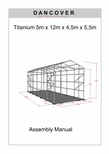
Titanium 5m x12m x4,5m x5,5mAssemblyManual
Table of content.1. FrontPage.2. Table of content.3. List of parts.4. Construction.7. Mounting the covers.9. Contact Information.
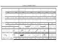
Part List For 5m x12m x 4,5m x 5,5mPart no. Description Quantity(pcs.)1 Curved Roof Tube at two ends (top) 22 Curved Roof Tube in the middle (top) 53 Curved Roof Tube at two ends (side) 44 Curved Roof Tube in the middle (top) 105 Sidewall with base plate (in the middle) 106 Sidewall with base plate (at two ends) 47 Upper sidewall at two ends 48 Upper sidewall in the middle 109 Lower Standing Legs with Base Plate (in front and back panel) 410 Standing legs in front and back panel (in the middle) 411 Standing legs in front and back panel (at two ends) 412 Roof Purlin and Horizontal Wall at both sides 9013 Cross tube (in the middle) in front and back panel 814 Cross Tube (at two ends) in front and back panel 1215 Slant supporting tube 816 Roof Cover 117 Front Cover 118 Back Cover 119 Stake Peg 3620 Rope for Fixing Cover21 Bolts M14x30 236M14x70 50M12x50 15M14x50 822 Inner joint for Cross Tubes and Slant Suporting Tubes 8
Assembly.Figure1Step#1:Placebaseplatesasshowninfigure#1.Makesurethatdiagonalsareequalinlength.Securebaseplateswithstakepegs.Makesuretouseatleast2stakepegsperbaseplateanddrivethem intothegroundsotheycrosseachotherasshownin figure#3.Step#2:Assembletwosidewalsandconnectthem asshowninfigure#2.Makesurethatalboltsaresecuredtightlyandplacedfrom theoutsideandin,toavoiddamageonthecover.Figure3and4showshow jointsshouldbeassembled,bothshownfrom inside.Figure2Figure3Figure4
Step#3:Connectthetwosidewalswiththecurvedrooftubes.Thenconnectthesewiththehorizontalbarsasshowninfigure#5.Figure#6and#7showhowjointsaresupposedtobeassembled.Step#4:AssemblethenexttwosidewalsinextensionofthealreadyerectedsidesasshownFigure5Figure6Figure7
Step#5Repeatsteps#3and#4untiltheentireframeshasbeenerected.Notethatyouhavetoinstalwindcrossesinthesidewalsectionsclosesttothecorners.(seeFigure#4).Itshouldlooklikefigure#8.Step#6:Makesurethatalboltsareinsertedfrom theoutsideinbeforeproceedingwiththecover.Makesurealfootplatesaresecuredtotheground.Figure8Figure9
MountingtheCoverStep#7Tieinacrossbeam inonesideofthecover.asshowninfigure#10.Step#8Pulthecoveroverthetopofthestructureusing3ropestiedtothecrossbeam.Seefigure#11Step#9:Makesurethatthecoversitsonevenlyonbothsidesoftheframe.Step#10:Tiethecovertothebotom tensioningbar.Makesurethatitistightened.Figure11Figure10
Step#11:Mountthefrontandthebackcoverbyweavingtheropearoundthebarsasshowninfigure#12and #13.Dothesamewiththeroofcover.Makesuretouseoneropeforeachcovers.Step#12:Makesurethattheedgeoftheroofcoveroverlapsthefront/backcover(overtheendbars)asshowninfigure#14.Slidearopethroughtheendsleevesandtightentheropethroughthehoopsofthecornerfootplates.Step#13:Makesurealropesaresecuredandtight.Figure12figure14Figure13


![[PDF Manual [DOWNLOAD HERE]] - Dancover shop](https://img.yumpu.com/35076643/1/184x260/pdf-manual-download-here-dancover-shop.jpg?quality=85)