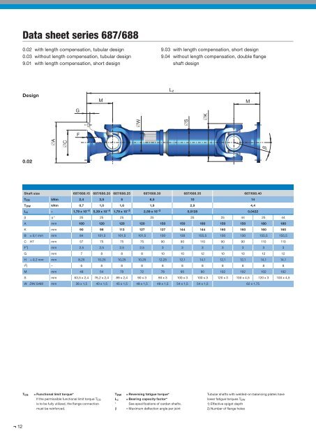
Data sheet series 687/6880.02 with length compensation, tubular design0.03 without length compensation, tubular design9.01 with length compensation, short design9.03 with length compensation, short design9.04 without length compensation, double flangeshaft designDesignML zMG∅W∅S∅KF∅A∅C0.02Shaft size 687/688.15 687/688.20 687/688.25 687/688.30 687/688.35 687/688.40T CS kNm 2,4 3,5 5 6,5 10 14T DW kNm 0,7 1,0 1,6 1,9 2,9 4,4Lc – 1,79 x 10 –4 5,39 x 10 –4 1,79 x 10 –3 2,59 x 10 –3 0,0128 0,0422b
Data sheet series 687/688DesignL f60°22,5°0.0345°L z∅B∅B9.019.03L f∅H6-hole flange∅H8-hole flangeNOTE: Hole patterns are not optional.Each cardan shaft size has a specific hole pattern.9.04Design Shaft size 687/688.15 687/688.20 687/688.25 687/688.30 687/688.35 687/688.400.020.039.019.039.04L z min mm 346 379 458 492 504 582 572 586 693 586 693L a mm 60 70 100 110 110 110 110 110 180 110 180G kg 5,7 8,4 12,0 13 14,2 24,0 25,6 28,7 30,3 29,4 30,9G R kg 3,62 4,37 5,13 6,44 6,44 7,18 7,18 8,66 10,6 8,66 10,6Jm kgm 2 0,0043 0,0089 0,0144 0,0245 0,0245 0,043 - 0,0676 0,0706 0,0776 0,0806Jm R kgm 2 0,0034 0,0059 0,0096 0,0122 0,0122 0,0169 0,0169 0,0296 0,0242 0,0296 0,0242C Nm/rad. 0,26 x 10 5 0,42 x 10 5 0,71 x 10 5 0,78 x 10 5 0,78 x 10 5 1,18 x 10 5 - 2,17 x 10 5 1,61 x 10 5 2,17 x 10 5 1,61 x 10 5C R Nm/rad. 0,34 x 10 5 0,60 x 10 5 0,98 x 10 5 1,25 x 10 5 1,25 x 10 5 1,72 x 10 5 1,72 x 10 5 3,02 x 10 5 2,47 x 10 5 3,02 x 10 5 2,47 x 10 5L f min mm 221 239 282 310 322 379 369 423 449 423 449G kg 4,1 5,8 8,6 8,6 9,8 18,0 19,6 22,8 21,0 23,4 21,6Jm kgm 2 0,0038 0,0085 0,0129 0,0238 0,0238 0,04 - 0,066 0,0628 0,076 0,0728C Nm/rad. 0,44 x 10 5 0,86 x 10 5 1,44 x 10 5 1,74 x 10 5 1,74 x 10 5 1,81 x 10 5 - 3,35 x 10 5 2,78 x 10 5 3,35 x 10 5 2,78 x 10 5L z min mm 296 322 361 379 391 510 500 505 525 505 525L a min mm 38 41 36 36 36 70 70 70 60 70 60L z max mm 348 381 425 453 465 550 540 545 645 545 645L a max mm 90 100 100 110 110 110 110 110 180 110 180L z min mm 245 274 313 331 343 419 409 441 – 441 –L a min mm 25 27 28 29 29 45 45 45 – 45 –L z max mm 280 317 355 397 409 484 474 506 – 506 –L a max mm 60 70 70 95 95 110 110 110 – 110 –L f min mm 192 216 280 288 312 380 360 408 408 408 408L z min = Shortest possible compressed lengthL a = Length compensationL f min = Shortest fi xed lengthL z + L a = Maximum operating lengthGG RJmJm R= Weight of shaft= Weight per 1.000 mm tube= Moment of inertia= Moment of inertia per 1.000 mm tubeCC R= Torsional stiffness of shaft without tube= Torsional stiffness per 1.000 mm tube13