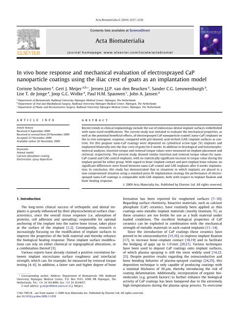
In vivo bone response and mechanical evaluation of ... - Dutch
In vivo bone response and mechanical evaluation of ... - Dutch
In vivo bone response and mechanical evaluation of ... - Dutch

You also want an ePaper? Increase the reach of your titles
YUMPU automatically turns print PDFs into web optimized ePapers that Google loves.
C. Schouten et al. / Acta Biomaterialia 6 (2010) 2227–2236 22292.6. Surgical procedureFour healthy female Saanen goats with an average age <strong>of</strong> 26–30 months <strong>and</strong> a mean body weight <strong>of</strong> 50–60 kg were selected.All in <strong>vivo</strong> work was conducted in accordance with ISO st<strong>and</strong>ards<strong>and</strong> the protocols <strong>of</strong> the Radboud University Nijmegen MedicalCenter, Nijmegen, The Netherl<strong>and</strong>s. National guidelines for care<strong>and</strong> use <strong>of</strong> laboratory animals were obeyed <strong>and</strong> the approval <strong>of</strong>the Radboud University Experimental Animal Ethical Committeewas obtained (RUDEC 2008-189). The St implants were insertedinto trabecular <strong>bone</strong> in the iliac crest, as described by Schoutenet al. [32]. All animals received subcutaneous injections <strong>of</strong> the prophylacticantibiotic Albipen Ò to reduce the risk <strong>of</strong> peri-operativeinfection: 15% Albipen at 3 ml 50 kg 1 pre-operative <strong>and</strong> AlbipenLA at 7.5 ml 50 kg 1 for 3 days post-operative (<strong>In</strong>tervet BV, Boxmeer,The Netherl<strong>and</strong>s). Surgery was performed under generalinhalation anesthesia <strong>and</strong> sterile conditions. Anesthesia was inducedby an intravenous injection <strong>of</strong> Pentobarbital Ò , after whichthe goats were intubated <strong>and</strong> connected to an inhalation ventilatorwith a constant volume <strong>of</strong> a mixture <strong>of</strong> nitrous oxide, is<strong>of</strong>lurane<strong>and</strong> oxygen. After intubation the incision sites <strong>and</strong> surroundingareas were shaved, washed <strong>and</strong> disinfected with povidone–iodine.For insertion <strong>of</strong> the St implants each animal was immobilized ina prone position. A transverse skin incision was made, starting atthe intermediate zone <strong>of</strong> the iliac crest (i.e. half way between theposterior superior iliac spine <strong>and</strong> anterior superior iliac spine), subsequentlyprocessing towards the anterior superior iliac spine (i.e.from medial to lateral) on both sides <strong>of</strong> the vertebral column(Fig. 1). The incision was continued through the underlying tissuelayers down to the periosteum. The periosteum was undercut <strong>and</strong>lifted aside, fully exposing the iliac crest. Subsequently cavitieswere created with a 2.0 mm pilot drill, which were gradually widenedusing drills <strong>of</strong> increasing size until a final diameter <strong>of</strong> 4.0 mmwas reached. Drilling was performed using a dental bur (Elcomed100, W&H Dental Werk Burmoos, Austria) at low rotational drillspeeds (800–1200 r.p.m.) <strong>and</strong> continuous external cooling withsaline solution. Four implant locations were created in each iliacwing, with an interimplant distance <strong>of</strong> about 1 cm (Fig. 1). Afterpreparation the implant locations were irrigated <strong>and</strong> the implantsinserted manually. For each iliac wing insertion torque values(torque-in) were measured for two implants using a MGT 50 Ò digitaltorque gauge (MARK-10 Corp., New York). <strong>In</strong> total 32 St implants(16 implants per experimental group) were implanted int<strong>of</strong>our goats. Following statistical r<strong>and</strong>omization, the implants wereclustered into groups <strong>of</strong> two implants (GAE vs. nano-CaP-coated).After implant placement the s<strong>of</strong>t tissue layers <strong>and</strong> skin were closedwith resorbable sutures (Vicryl Ò 40, Ethicon Products, Amersfoort,The Netherl<strong>and</strong>s). To reduce post-operative pain, Finadyne Ò wasadministered for 2 days post-operatively. After 6 weeks implantationall four goats were euthanized with an overdose <strong>of</strong>Nembutal Ò .2.7. Implant retrievalImmediately after killing the animals the implants, with surroundingtissues, were explanted <strong>and</strong> excess tissue was removed.Half <strong>of</strong> the specimens (16 specimens, 8 nano-CaP <strong>and</strong> 8 GAEcontrols) were stored on ice for subsequent <strong>mechanical</strong> testing(torque-out). The remaining specimens for histological analysis(16 specimens, 8 nano-CaP <strong>and</strong> 8 GAE controls) were fixed in10% neutral buffered formalin solution for further histologicalprocessing.2.8. Mechanical testing2.8.1. Torque testingTorque-out values, i.e. the value necessary to remove the implantfrom the <strong>bone</strong> specimen, were determined using a digital torquegauge (MARK-10 Corp., New York). Then the specimens wereembedded in a mold with gypsum <strong>and</strong> placed in a jig, whichformed part <strong>of</strong> a tensile bench (Fig. 2). A controlled, graduallyincreasing rotational force (displacement 0.5 mm min 1 ) was appliedto each implant until implant loosening. The peak force measuredat implant loosening was scored as the torque-out value.Following the torque measurements the specimens were fixedin 10% neutral buffered formalin solution, dehydrated in a gradedseries <strong>of</strong> ethanol <strong>and</strong> embedded in methyl methacrylate (MMA).After polymerization non-decalcified longitudinal sections <strong>of</strong> theimplants were prepared <strong>and</strong> stained with methylene blue <strong>and</strong> basicfuchsin <strong>and</strong> examined using a light microscope. The histologicalFig. 1. Schematic representation <strong>of</strong> the pelvis <strong>of</strong> the goat. The numbered cavities represent the four implant locations in the iliac crest.
2230 C. Schouten et al. / Acta Biomaterialia 6 (2010) 2227–2236Fig. 2. Representation <strong>of</strong> the torque removal set-up. (A) After harvesting the <strong>bone</strong> specimens, containing one St implant each, were embedded in a mold with gypsum. (B) Fordetermination <strong>of</strong> the torque-out value the mold was placed in a jig, which is part <strong>of</strong> a tensile bench. Subsequently, a controlled, gradually increasing, longitudinal force wasapplied via the tensile bench to each implant until it loosened. The peak force measured at implant loosening was scored as the torque-out value.sections were examined to determine the fracture plane <strong>of</strong> the<strong>mechanical</strong>ly tested implants.2.9. Histological preparationsAfter fixation in 10% neutral buffered formalin solution thespecimens for histological processing were dehydrated graduallyin ethanol solutions from 70% to 100% <strong>and</strong> subsequently embeddedin MMA. Following polymerization non-decalcified 10 lm thicklongitudinal sections <strong>of</strong> the implants were prepared (at least threefor each implant) using a modified sawing microtome technique[33] <strong>and</strong> subsequently stained with methylene blue <strong>and</strong> basicfuchsin.2.10. Histological <strong>and</strong> histomorphometrical <strong>evaluation</strong>To evaluate the <strong>bone</strong> <strong>response</strong> around the implants, histological<strong>evaluation</strong> was carried out using a light microscope (Axio ImagerMicroscope Z1, Carl Zeiss Micro Imaging GmbH, Göttingen, Germany)equipped with a computer-based image analysis system(Leica Qwin Pro-image analysis s<strong>of</strong>tware, Leica Imaging Systems,Cambridge, UK) to perform histomorphometrical analyses. Quantitativemeasurements were conducted for three different sectionsper specimen, on each side <strong>of</strong> the two-dimensional histologicalimage (at magnification; 31.5), resulting in a total <strong>of</strong> six measurementsper specimen. Bone–implant contact (BC) <strong>and</strong> peri-implant<strong>bone</strong> volume (BV) were the parameters assessed. BC was calculatedas the percentage <strong>of</strong> implant surface in direct contact with<strong>bone</strong>, without any fibrous tissue interposition. To determine theperi-implant BV three regions <strong>of</strong> interest (ROI) were set along thelong axis <strong>of</strong> the implant for each individual sample, starting atthe first coronal screw thread <strong>of</strong> the St implants (Fig. 3). The inner,middle <strong>and</strong> outer zone was marked, with a st<strong>and</strong>ardized length <strong>of</strong>4000 lm <strong>and</strong> a height <strong>of</strong> 500 lm. BV was defined as the percentage<strong>of</strong> the total ROI occupied by <strong>bone</strong> tissue.2.11. Statistical analysisAll measurements were statistically evaluated using SPSS,version 16.0 (SPSS <strong>In</strong>c., Chicago, IL). Paired t-tests were used forcomparison <strong>of</strong> torque-in <strong>and</strong> torque-out values for the GAE vs.nano-CaP-coated implants. Paired t-tests were also used to testthe differences between the two experimental groups for BC, BV<strong>and</strong> the three individual BV zones (inner, middle <strong>and</strong> outer). Statisticalsignificancy was set at a probability value <strong>of</strong> P < 0.05.Fig. 3. Schematic representation <strong>of</strong> the quantification <strong>of</strong> <strong>bone</strong> contact (BC) <strong>and</strong><strong>bone</strong> volume (BV) for histomorphometrical analysis. BC was calculated as thepercentage <strong>of</strong> implant surface (4000 lm) which is in direct contact with <strong>bone</strong>. Todetermine the amount <strong>of</strong> peri-implant <strong>bone</strong> volume three ROI were set for eachindividual sample along the length <strong>of</strong> the implant, starting at the first coronal screwthread <strong>of</strong> the St implants. An inner, middle <strong>and</strong> outer zone were marked, with ast<strong>and</strong>ardized length <strong>of</strong> 4000 lm <strong>and</strong> a width <strong>of</strong> 500 lm. The peri-implant <strong>bone</strong>volume was defined as the percentage <strong>of</strong> the total area <strong>of</strong> interest in which <strong>bone</strong>was present.3. Results3.1. Electrosprayed coatings3.1.1. Surface characterizationFig. 4 displays SEM images <strong>of</strong> the GAE (Fig. 4A <strong>and</strong> B) <strong>and</strong> electrosprayednano-CaP-coated (Fig. 4C <strong>and</strong> D) St implant surfaces.The GAE implants showed a rough surface appearance in accordancewith the surface treatment. The nano-CaP coating showeda rough, porous network <strong>of</strong> densely packed nano-CaP particles distributedover the entire implant surface. At higher magnification(Fig. 4D) the nano-CaP coatings appeared to have granular depositions<strong>of</strong> different sizes on top <strong>of</strong> <strong>and</strong> in between the porousnetwork.The thickness <strong>of</strong> the coatings was measured using partiallycoated silicon wafers, which were subjected to AFM. Results obtainedwith AFM elucidated an electrosprayed nano-CaP coatingthickness <strong>of</strong> 400 ± 50 nm.The results <strong>of</strong> the surface roughness measurements usingUST showed an average surface roughness value (R a ) <strong>of</strong> 1.33 ±0.01 lm for GAE surfaces <strong>and</strong> 1.28 ± 0.10 lm for nano-CaP-coatedsurfaces.
C. Schouten et al. / Acta Biomaterialia 6 (2010) 2227–2236 2231Fig. 4. SEM images <strong>of</strong> an GAE implant surface (A <strong>and</strong> B), <strong>and</strong> a nano-CaP-coated implant surface (C <strong>and</strong> D). Original magnifications: 500 (A <strong>and</strong> C); 2000 (B <strong>and</strong> D).3.2. Implantation <strong>of</strong> St implants in artificial <strong>bone</strong>Results obtained with the OCPC method demonstrated that64.4 ± 4.0% <strong>of</strong> the calcium in the nano-CaP coatings remained onthe implant surface after implantation in artificial <strong>bone</strong>. Furthermore,<strong>evaluation</strong> <strong>of</strong> the morphological appearance <strong>of</strong> the electrosprayednano-CaP coatings before <strong>and</strong> after implantation in theartificial <strong>bone</strong> using SEM showed that the implant surface was stillcompletely covered with the nano-CaP coating after implantation(data not shown).3.3. <strong>In</strong> <strong>vivo</strong> implantation experiment3.3.1. General observations on experimental animalsThroughout the experimental period all four goats remained ingood health <strong>and</strong> did not show any post-operative wound healingcomplications. After 6 weeks a total <strong>of</strong> 32 implants were retrieved– all 32 St implants were still in situ (i.e. surrounded by <strong>bone</strong>).Macroscopically, the implants remained intact <strong>and</strong> no inflammatorysigns or adverse tissue reactions were observed.3.3.2. Torque testingDuring removal torque testing one nano-CaP-coated St implantappeared to be loosened <strong>and</strong> was therefore excluded fromthe torque-out measurements. The results <strong>of</strong> the insertion (torque-in)<strong>and</strong> removal torque (torque-out) measurements for bothexperimental groups (GAE <strong>and</strong> nano-CaP-coated) are depicted inFig. 5 <strong>and</strong> Table 1. Mean torque-in values were 32.1 <strong>and</strong>32.8 N cm 1 for the GAE <strong>and</strong> nano-CaP-coated implants, respectively.Mean torque-out values after 6 weeks implantation were42.8 <strong>and</strong> 36.8 N cm 1 for the GAE <strong>and</strong> nano-CaP-coated implants,respectively. Regarding the mean difference in torque-in valuesfor the two experimental groups, no significant differences wereobserved. Similarly, no significant differences were observed forthe torque-out values for the GAE <strong>and</strong> nano-CaP-coated groups.Additionally, the torque-in <strong>and</strong> torque-out values for eachFig. 5. Results <strong>of</strong> the torque testing showing mean values ± SD (N cm 1 ) for both experimental groups for insertion (torque-in) <strong>and</strong> removal (torque-out) torque values.
2232 C. Schouten et al. / Acta Biomaterialia 6 (2010) 2227–2236Table 1Mean values ± SD (N cm 1 ) <strong>and</strong> the outcome <strong>of</strong> the statistical analyses for bothexperimental groups regarding insertion (torque-in) <strong>and</strong> removal (torque-out) torquevalues.GAE Nano-CaP-coated P valueTorque-in 32.06 ± 8.85 32.77 ± 12.37 0.90Torque-out 42.80 ± 20.87 36.81 a ± 14.62 0.54aOne nano-CaP-coated implant appeared to be loosened upon removal torquetesting <strong>and</strong> was therefore excluded from the analysis.individual group were analyzed <strong>and</strong> also did not show significantdifferences.Light microscopic examination <strong>of</strong> the fracture plane <strong>of</strong> specimenssubjected to torque testing showed similar results for theGAE <strong>and</strong> nano-CaP-coated implants. After 6 weeks implantationthe fracture plane was observed to be located at the implant–coatinginterface (Fig. 6).3.3.3. Descriptive histological <strong>evaluation</strong>Light microscopic examination <strong>of</strong> methylene blue/basic fuchsinstained sections <strong>of</strong> the retrieved specimens demonstratedvariable amounts <strong>of</strong> <strong>bone</strong> inside <strong>and</strong> on top <strong>of</strong> the threads <strong>of</strong>the St implants (Fig. 7). All implants were inserted for the majorpart into trabecular <strong>bone</strong>. No apparent differences between thetwo experimental groups were observed. On more detailedobservation it was observed that generally for all St implants,irrespective <strong>of</strong> surface modification, the peripheral pitch <strong>of</strong> thethreads was in close contact with the surrounding <strong>bone</strong> tissue.Moreover, it was observed that the <strong>bone</strong> present in the pitchwas conducted along the implant surface into the threads. Astriking observation in various sections was the presence <strong>of</strong> acartilaginous growth plate at the top <strong>of</strong> the iliac crest, fromwhich in some cases an intervening fibrous tissue layer waspresent along the implant surface.3.3.4. Histomorphometrical analysisMean data regarding BC <strong>and</strong> BV <strong>and</strong> the outcome <strong>of</strong> statisticalanalyses between the experimental groups for the three peri-implantzones (inner, middle <strong>and</strong> outer) are depicted in Fig. 8 <strong>and</strong>Table 2.3.3.4.1. Bone contact. Overall data for <strong>bone</strong>–implant contact did notshow significant differences between the GAE (23.2%) <strong>and</strong> nano-CaP-coated group (23.0%) groups (Fig. 8A).3.3.4.2. Bone volume. Regarding overall <strong>bone</strong> volume, no significantdifferences were observed between the GAE (40.9%) <strong>and</strong>nano-CaP-coated (38.8%) groups (Fig. 8B). Additionally, the <strong>bone</strong>volume values for the different peri-implant zones (inner, middle<strong>and</strong> outer) showed no significant differences between the GAE(43.3%, 42.1% <strong>and</strong> 37.5%) <strong>and</strong> nano-CaP-coated (41.5%, 38.6%<strong>and</strong> 36.2%) groups.4. DiscussionThe current study was initiated to evaluate the <strong>mechanical</strong>properties <strong>and</strong> the in <strong>vivo</strong> <strong>bone</strong> <strong>response</strong> to electrosprayed nano-CaP-coated implants compared with GAE implant surfaces, usingthe iliac crest <strong>of</strong> goats as an implantation model. The results <strong>of</strong>the present study show that electrosprayed nano-CaP coatings performto a comparable extent to GAE implants, both with respect toimplant fixation <strong>and</strong> <strong>bone</strong> healing <strong>response</strong>.4.1. Coating propertiesThe electrospray deposition technique, as used for the deposition<strong>of</strong> nano-CaP coatings in the present study, is a so-calledline-<strong>of</strong>-sight deposition technique. For deposition <strong>and</strong> characterization<strong>of</strong> the coatings on the dental implants used in the presentstudy several practical issues are involved. First,determination <strong>of</strong> coating thickness directly on the implant surfacewas impossible due to (i) the pre-existing surface roughnessresulting from the grit blasting <strong>and</strong> acid etching procedure, (ii)the three-dimensional configuration <strong>of</strong> the implants <strong>and</strong> (iii)the presence <strong>of</strong> screw threads on the implant surface. Consequently,coating thickness was determined using a validatedmodel system (unpublished results) in which planar siliconFig. 6. Histological sections <strong>of</strong> a screw-type (St) implant coated with a nano-CaP-coating after <strong>mechanical</strong> torque testing (A <strong>and</strong> B). After 6 weeks implantation the fractureplane was observed to be located at the implant–coating interface (see arrows). Magnification: (A) 31,5; (B) 126.
C. Schouten et al. / Acta Biomaterialia 6 (2010) 2227–2236 2233Fig. 7. Representative histological sections <strong>of</strong> St implants after 6 weeks implantation in the crista iliaca <strong>of</strong> goats. (A <strong>and</strong> B) GAE; (C <strong>and</strong> D) nano-CaP-coated implants.Magnification: (A <strong>and</strong> C) 31,5; (B <strong>and</strong> D) 126.wafers serve as model substrates for coating deposition. Second,complete surface coverage <strong>of</strong> a three-dimensional dental implantby the electrospray deposition technique can only be achievedby either continuous rotation <strong>of</strong> the implant during coatingdeposition or performing multiple coating deposition runs, asin the present study. Although the authors are aware <strong>of</strong> the factthat the option <strong>of</strong> continuous rotation <strong>of</strong> the implant duringcoating deposition is preferable for homogeneous coating thicknessover the entire implant surface, the experimental set-up<strong>of</strong> the electrospray equipment lacks a rotational implant holder.Consequently, the dental implants were coated in two runs thatresulted in complete surface coverage by nano-CaP, as was seenby electron microscopy.4.2. Mechanical testingTorque-out tests determine the force that is needed to loosenimplants from their surrounding <strong>bone</strong>, which is indicative <strong>of</strong> the<strong>bone</strong>–implant interface strength [34]. The present study showedsimilar mean torque values for the nano-CaP-coated <strong>and</strong> GAEimplants, with high variation (i.e. st<strong>and</strong>ard deviation) withineach individual group. The high intra-group variation most likelyresulted from variations in implant location within the iliaccrest, used for reasons <strong>of</strong> statistical r<strong>and</strong>omization. It is straightforwardto hypothesize that in this way location-dependent effectsare minimized, albeit that variations in torque valuesincrease due to slight differences in the anatomical surrounding<strong>of</strong> the implants. From a <strong>mechanical</strong> point <strong>of</strong> view this lack <strong>of</strong> differencecan be explained by the comparable surface roughnessvalues for both experimental groups (R a 1.3 lm). However, inaddition to surface roughness, surface composition plays a majorrole in obtaining an optimal <strong>bone</strong>–implant interface [35,36]. Surprisingly,addition <strong>of</strong> the nano-CaP coating did not result in animprovement in <strong>bone</strong> bonding. The reasons for this lack <strong>of</strong> abeneficial effect <strong>of</strong> the nano-CaP could be multiple. Outsidersmight speculate that detachment <strong>of</strong> the coating upon insertionis a likely cause. However, indirect evidence exists that contradictssuch speculations. Several studies showed that thin nanosizedCaP coatings, up to 400 nm, mainly consist <strong>of</strong> poorlycrystalline particles [28,37,38]. As coating crystallinity <strong>and</strong><strong>mechanical</strong> strength are positively related, nanometer thin electrosprayedCaP coatings need a certain degree <strong>of</strong> crystallinity inorder to ensure interfacial adhesion to the substrate <strong>and</strong> sufficient<strong>mechanical</strong> strength <strong>of</strong> the applied coating upon implantation[39]. However, as shown in the assay using artificial <strong>bone</strong>,the nanometer thin CaP coatings did show sufficient adhesionstrength to withst<strong>and</strong> the shear <strong>and</strong> compressive forces uponimplantation, as expressed by a coating retention <strong>of</strong> 64%. Anotherspeculative reason for the lack <strong>of</strong> an additional favorableeffect <strong>of</strong> the nano-CaP coating might be fast dissolution <strong>of</strong> thecoating. It has been reported by Wolke et al. that the dissolutionbehavior <strong>of</strong> coatings is determined by the degree <strong>of</strong> coating crystallinity,i.e. a lower degree <strong>of</strong> crystallinity causes a higher dissolutionrate [40]. <strong>In</strong> view <strong>of</strong> this, it can be hypothesized that inthe current study dissolution <strong>of</strong> the coating occurred before ithad a chance to influence the <strong>bone</strong> healing <strong>response</strong>. Dissolution<strong>of</strong> CaP ceramic coatings can be enhanced by the local <strong>bone</strong> conditionsafter creation <strong>of</strong> the wound bed, which is associated witha decrease in pH [40]. <strong>In</strong> view <strong>of</strong> this, coating dissolution as apossible cause for the lack <strong>of</strong> a significant effect cannot be ruledout <strong>and</strong> needs to be addressed in future experimental work onelectrosprayed nano-CaP coatings. A final explanation might bethat, within the context <strong>of</strong> the experimental model used, addition<strong>of</strong> the nano-CaP coating could not improve the already
2236 C. Schouten et al. / Acta Biomaterialia 6 (2010) 2227–2236[43] Munting E, Wilmart JF, Wijne A, Hennebert P, Delloye C. Effect <strong>of</strong> sterilizationon osteoinduction. Comparison <strong>of</strong> five methods in demineralized rat <strong>bone</strong>.Acta Orthop Sc<strong>and</strong> 1988;59(1):34–8.[44] Mendonca G, Mendonca DBS, Aragao FJL, Cooper LF. Advancing dental implantsurface technology – from micron- to nanotopography. Biomaterials2008;29(28):3822–35.[45] Schouten C, van den Beucken JJJP, de Jonge LT, Bronkhorst EM, Meijer GJ,Spauwen PHM, et al. The effect <strong>of</strong> alkaline phosphatase coated onto titaniumalloys on <strong>bone</strong> <strong>response</strong>s in rats. Biomaterials 2009;30(32):6407–17.[46] Conner KA, Sabatini R, Mealey BL, Takacs VJ, Mills MP, Cochran DL. Guided<strong>bone</strong> regeneration around titanium plasma-sprayed, acid-etched, <strong>and</strong>hydroxyapatite-coated implants in the canine model. J Periodontol2003;74(5):658–68.[47] He FM, Yang GL, Wang XX, Zhao SF. Bone <strong>response</strong>s to rough titaniumimplants coated with biomimetic Ca–P in rabbit tibia. J Biomed Mater Res B2009;90B(2):857–63.[48] O’Sullivan D, Sennerby L, Meredith N. <strong>In</strong>fluence <strong>of</strong> implant taper on theprimary <strong>and</strong> secondary stability <strong>of</strong> osseointegrated titanium implants. ClinOral Implants Res 2004;15(4):474–80.[49] Shalabi MM, Wolke JGC, Jansen JA. The effects <strong>of</strong> implant surface roughness<strong>and</strong> surgical technique on implant fixation in an in vitro model. Clin OralImplants Res 2006;17(2):172–8.