Columbia 350, 400 - Avidyne
Columbia 350, 400 - Avidyne
Columbia 350, 400 - Avidyne

You also want an ePaper? Increase the reach of your titles
YUMPU automatically turns print PDFs into web optimized ePapers that Google loves.
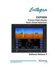
600-00102-000 Rev 6<strong>Columbia</strong> <strong>350</strong>, <strong>400</strong>Multi-Function DisplayPilot’s Guide
SW Part Num MFD ChecklistVersionAircraft<strong>Columbia</strong>ChecklistVersion530-00180-200 1.01 <strong>Columbia</strong> <strong>350</strong> RB050000 Rev J03/24/04<strong>Columbia</strong> <strong>400</strong> RC050002 Rev -11/10/04Entegra EX5000 -i- 600-00102-000 Rev 6
Document Revision HistoryDate Revision DescriptionJul 22, 2003 00 Released per ECO 03-188Sept 11, 2003 01 Updated per ECO 03-225Apr 5, 2004 02 Updated per ECO 04-042Jun 10, 2004 03 Updated per ECO 04-076Jan 14, 2005 04 Updated per ECO 04-241Feb 1, 2005 05 Updated per ECO 05-020Sept 14, 2005 06 Updated per ECO 05-157System ConfigurationWhen contacting your dealer or <strong>Avidyne</strong> technical support, and whenlogging onto My<strong>Avidyne</strong>.com for the first time, please have yourEntegraEX5000 serial number and Subscriber Communicator serialnumber available:EntegraEX5000 S/N: _______________________ _________Datalink Subscriber Communicator S/N: ___________________This document is applicable to Software Part Number 530-00180-200.All materials copyrighted including images that represent this softwareCopyright 2005 <strong>Avidyne</strong> Corporation. All rights reserved.600-00102-000 Rev 6 -ii- Entegra EX5000
Table of ContentsTable of Contents1 Introduction .............................................................. 1About this Guide ..........................................................................4Notes and Warnings ....................................................................5Copyrights and Trademarks.........................................................8AVIDYNE EXCLUSIVE LIMITED WARRANTY/LIMITATIONS ONLIABILITY.....................................................................................9Using the Entegra EX5000 MFD................................................112 Map Page................................................................. 13Map Page—Controls..................................................................14Map Page Symbols—Terrain and Position ................................18Map Page Symbols—Runways and Flight Plan ........................22Map Orientation Control.............................................................24Errors Displayed on the Map Page ............................................25Loss of GPS Input ...............................................................25Loss of Heading Input..........................................................253 Traffic Mode and the Traffic Page ........................ 27The Dedicated Traffic Page .......................................................27Traffic Symbols ..........................................................................30TIS Sensor Status......................................................................314 CMax Chart Pages (Optional) ............................... 32About CMax ...............................................................................32About Geo-Referenced Charts ..................................................33CMax Chart Page ......................................................................33CMax Views ...............................................................................38Procedure Chart Views........................................................38Airport Chart Views..............................................................40CMax Selection Page ................................................................42Selecting an Airport....................................................................44Chart NOTAMs Page...........................................................465 Trip Page................................................................. 48Trip Page Information ................................................................496 Nearest Page (NRST) ............................................. 55Nearest Page .............................................................................55Airport Info Page ........................................................................587 Checklists ............................................................... 59Checklist Versions .....................................................................59Normal Checklists ......................................................................60Entegra EX5000 -iii- 600-00102-000 Rev 6
Checklist Buttons and Knobs..................................................... 62Emergency Checklists ............................................................... 648 Aux Page – Configuring the EX5000.................... 67Aux Main Page .......................................................................... 68Airport Filter Setup Page ........................................................... 70Declutter Setup Page ................................................................ 72Data Block Edit Page................................................................. 74System Time Page .................................................................... 76Datalink Configuration Page...................................................... 789 Engine Page ........................................................... 82Engine Page Overview .............................................................. 82Engine Page .............................................................................. 84Initial Usable Fuel Page............................................................ 88<strong>Columbia</strong> <strong>350</strong> Lean Assist......................................................... 89Leaning for Best Power....................................................... 89Leaning for Best Economy.................................................. 90<strong>Columbia</strong> <strong>400</strong> Lean Assist......................................................... 91Leaning for Best Power....................................................... 91Leaning for Best Economy.................................................. 92Data Blocks on Map Page ......................................................... 94Lean Data Block States....................................................... 94Engine Sensor Status Box .................................................. 94EMax Engine Monitor ................................................................ 9510 Using Datalink........................................................ 96About Datalink Services ............................................................ 96Overview of Datalink Weather ................................................... 97About Narrowcast Datalink ........................................................ 99Setting up a Narrowcast Account........................................ 99Flight Tracking..................................................................... 99Using Narrowcast Datalink in Flight .................................... 99Loss of Satellite Coverage ................................................ 100About Broadcast Datalink ........................................................ 101Setting up a Broadcast Datalink Account.......................... 101Using Broadcast Datalink in Flight .................................... 101About Broadcast Datalink Weather................................... 101Map Page with Datalink Weather ............................................ 103Symbols Displayed using Datalink .................................... 105Using Datalink without a Traffic Sensor ............................ 107600-00102-000 Rev 6 -iv- Entegra EX5000
Table of ContentsTrip Page with Datalink Weather .............................................108Nearest Page with Datalink Weather .......................................109About Multilink..........................................................................110Using Multilink ...................................................................110Setting up a Multilink Account ...........................................110Using Multilink Features ....................................................111Viewing Multilink Data .......................................................111Optimizing your Multilink Setup .........................................114Multilink Usage Guidelines ................................................116Datalink Messaging..................................................................117Messaging Knobs and Buttons..........................................118Using Datalink Messaging .................................................12011 Reference.............................................................. 123Updating Your Databases........................................................124Loading NavData (the Navigation Database) ....................125Loading CMax Chart Data .................................................127Downloading EMax Data ...................................................128Broadcast Datalink Service Purchase and Activation ..............130Creating Your XM WX Account .........................................130Activating Your Account ....................................................130Cleaning the EX5000 Screen...................................................132Sensor Status Block Symbols .................................................133Map Symbols ...........................................................................135Line Styles ...............................................................................137Data Blocks ...........................................................................139Nav Messages .........................................................................141Traffic Messages......................................................................142Lightning Messages .................................................................144Engine Messages ....................................................................146PFD Messages ........................................................................147Narrowcast Datalink Messages ...............................................148Broadcast Datalink Messages ................................................15012 Software License.................................................. 154Entegra EX5000 -v- 600-00102-000 Rev 6
List of FiguresFigure 1.1 Entegra EX5000 Initialization Page .................................. 2Figure 1.2 Entegra EX5000 MFD .................................................... 11Figure 2.1 Map Page Controls ......................................................... 14Figure 2.2 Map Page Symbols–Terrain and Position ...................... 18Figure 2.3 Map Page Symbols—Runways and Flight Plan ............. 22Figure 3.1 Map Page—Traffic Mode................................................ 28Figure 4.1 CMax Chart Page (Airport) ............................................. 34Figure 4.2 CMax Chart Page (Procedure) ....................................... 36Figure 4.3 Procedure Chart views ................................................... 39Figure 4.4 Airport Chart Views......................................................... 40Figure 4.5 Airport Departure Chart (Night View).............................. 41Figure 4.6 CMax Selection Page ..................................................... 42Figure 4.7 Airport Selection Page .................................................... 44Figure 4.8 Chart NOTAMs Page...................................................... 46Figure 5.1 Trip Page Information ..................................................... 49Figure 6.1 Nearest Page.................................................................. 55Figure 6.2 Airport Information Page................................................. 58Figure 7.1 Normal Procedure Checklist ........................................... 60Figure 7.2 Normal Checklists........................................................... 61Figure 7.3 Emergency Checklists .................................................... 64Figure 8.1 Aux Main Page ............................................................... 68Figure 8.2 Airport Filter Setup Page ................................................ 70Figure 8.3 Declutter Setup Page ..................................................... 72Figure 8.4 Data Block Edit Page...................................................... 74Figure 8.5 System Time Page ......................................................... 76Figure 8.6 Datalink Configuration Page ........................................... 79Figure 9.1 <strong>Columbia</strong> <strong>400</strong> Engine Main Page ................................... 84Figure 9.2 <strong>Columbia</strong> <strong>400</strong> Initial Usable Fuel Page........................... 88Figure 9.3 Engine Information—Map Page...................................... 94Figure 10.1 Broadcast Datalink Weather Boundaries.................... 102Figure 10.2 Datalink Weather—Map Page .................................... 103Figure 10.3 Broadcast Datalink Weather ....................................... 105Figure 10.4 Datalink Weather without Traffic Sensors................... 107Figure 10.5 Trip Page with Datalink Weather ................................ 108Figure 10.6 Nearest Page with Broadcast Datalink ....................... 109Figure 10.7 Broadcast Datalink NEXRAD Coverage ..................... 112Figure 10.8 Narrowcast and Broadcast DatalinkNEXRAD Coverage ....................................................................... 112Figure 10.9 Broadcast Datalink, without Canadian METARs......... 113600-00102-000 Rev 6 -vi- Entegra EX5000
List of FiguresFigure 10.10 Multilink Datalink with Canadian METAR flags .........114Figure 10.11 XM WX NEXRAD Coverage Area .............................115Figure 10.12 Datalink Messaging Knobs and Buttons....................118Figure 10.13 Receiving a Datalink Message ..................................122Entegra EX5000 -vii- 600-00102-000 Rev 6
List of TablesTable 2.1 Track Indicator Graphics................................................. 19Table 2.2 Obstacle.......................................................................... 24Table 3.1 Traffic Symbols ............................................................... 30Table 4.1 Airport Procedure Views ................................................. 39Table 4.2 Airport Chart Views ......................................................... 40Table 10.1 Message Status Indicators.......................................... 119Table 10.2 NOC Message Text Colors ......................................... 119Table 11.1 Sensor Status Block Symbols..................................... 133Table 11.2 Broadcast Datalink Sensor Status Block (Optional).... 134Table 11.3 Map Symbols – Airports.............................................. 135Table 11.5 Map Symbols – Traffic Symbols ................................. 136Table 11.6 Map Symbols – Other ................................................. 136Table 11.4 Map Symbols – Navigational Fixes............................. 136Table 11.7 Airspace and Airways Lines........................................ 137Table 11.8 SUA and TFR Status Lines......................................... 137Table 11.9 AIRMET and SIGMET Boundary Lines....................... 138Table 11.10 Data Block Information.............................................. 139Table 11.11 Engine Instrument Data Block Information ............... 140Table 11.12 Nav Messages .......................................................... 141Table 11.13 Traffic Messages....................................................... 142Table 11.14 Lightning Messages .................................................. 144Table 11.15 Engine Messages ..................................................... 146Table 11.16 PFD Messages ......................................................... 147Table 11.17 Narrowcast Datalink Messages ................................ 148Table 11.18 Broadcast Datalink Messages .................................. 150600-00102-000 Rev 6 -viii- Entegra EX5000
1 IntroductionThe EntegraEX5000 Multi-Function Display (MFD) provides apictorial view of your flight situation based on input from your GPSnavigator. It uses on-board database information for mappingnavigation data such as nearby airports, VORs, NDBs, special-useand other airspace, etc., as well as terrain, water, and obstacledatabases. The EX5000 also offers the following standard andoptional features:●●●●●●●Engine instruments display.Normal and Emergency Checklist display.Lightning information display from a WX-500 lightning sensor, ifinstalled.Full ARINC-429 databus capability, allowing the EX5000 todisplay curved flight paths, procedure turns, and holding patternsfrom a compatible GPS navigator.Traffic information display from L-3 Skywatch, Ryan TCAD, orGarmin TIS traffic systems.Terminal procedure chart display using the CMax function.Display of weather and flight restriction information wheninterfaced with an external Broadcast Datalink receiver or internalNarrowcast Datalink receiver.Note: Consult the Flight Manual Supplement (FMS) provided with theaircraft and/or sensors prior to operation. The FMS contains informationspecific to your installation and may contain operating limitations applicableto your aircraft configuration.Entegra EX5000 -1- 600-00102-000 Rev 6
On power up, the system performs a brief hardware self-test, thensystematically initializes its functions. After the system initializes(about a minute after power-on), the title page, with databasecurrency information, is displayed. Check to ensure that you do nothave any expired databases before continuing.When the EX5000 is ready, the “Press any bezel key to continue”message displays.Figure 1.1 Entegra EX5000 Initialization PageThe EX5000 Startup Page reports the valid dates for the currentlyloaded CMax chart data and NavData. Check to ensure that you donot have any expired databases before continuing.For CMax data:● If the issue date for the next update has passed, the StartupPage displays “Update Available” in white.600-00102-000 Rev 6 -2- Entegra EX5000
Introduction●If the current date is more than a week past the issue of the nextupdate, “Update Required” displays in yellow cautionary text.● If CMax is more than 10 weeks out of date, access to the charts isrevoked until new CMax data is loaded.For NavData, the date range displays if the data is valid; if it is notvalid, the word “EXPIRED” and the expiration data display in yellow.For more information about updating CMax and NavData, seeSection 11.1, "Updating Your Databases" on page 124.Entegra EX5000 -3- 600-00102-000 Rev 6
About this Guide1.1 About this GuideThis guide assumes that all available sensors and software optionshave been installed in your airplane. The page layouts and buttondescriptions in this guide may differ slightly from what you observe onyour EX5000. If your system is configured with a partial set of theavailable sensors, then some views may differ from this guide.Note: All images contained within this document, including screenshots andother displays, are for reference use only and are subject to change. Theimages contained herein may differ slightly from your actual equipment ordisplay.600-00102-000 Rev 6 -4- Entegra EX5000
Introduction1.2 Notes and WarningsNotes and warnings provide guidance for the use of the EX5000.<strong>Avidyne</strong> strongly suggests that you pay close attention to notes andwarnings for your own safety.For example:Note: Notes provide useful information about how to use the EX5000.!Warnings are prefaced with exclamation points and denoteinformation that can prevent serious injury or death on thepart of the user.The instructions and warnings in this manual are not intended toreplace the instructions and warnings for other equipment on youraircraft. It is critical that you as the pilot in command have a completeunderstanding of the warnings, operating instructions, and limitationsfor all equipment installed on your aircraft.!!!This manual assumes that the reader is an appropriatelylicensed pilot. <strong>Avidyne</strong> strongly recommends that you use theEX5000 only under VFR conditions until you are very familiarwith the EX5000.If you have questions, please contact <strong>Avidyne</strong> at 800-284-3963 (800-AVIDYNE) before operating with the EX5000 underIFR conditions.Before conducting flight operations, be sure to verify that timeand date settings on the System Time Setup Page are correctand in GMT (UTC). It is critical that the time be set to GMT toprovide accurate display of Datalink weather. See Section8.1, "Aux Main Page" on page 68 for more information.When using the EX5000, be sure to cross-check the datadisplayed against other data sources for accuracy includingother flight deck instruments and charts.Entegra EX5000 -5- 600-00102-000 Rev 6
Notes and Warnings!!!!!The displayed terrain and obstacle indicators are onlyadvisory. Do not rely on the EX5000 as the sole source ofobstacle and terrain avoidance information. Always refer tocurrent aeronautical charts for appropriate terrain andobstacle information.The EX5000 is not intended to replace your navigation chartsor primary navigation aids. Use the EX5000 as a supplementto other navigation sources, to enhance your overallsituational awareness. Do not rely on the navigation data inyour EX5000 as your sole reference for navigation.While a properly updated database contains the latest officialinformation available, the manufacturers will not be heldresponsible for any inaccuracy or omissions therein. Neveruse the terrain displayed on the EX5000 as the only referencefor terrain avoidance.The transmission of datalink weather information means thereis some delay from real time until the weather information isdisplayed on the EX5000. Therefore, use datalink weatherinformation only for strategic route planning. Avoid severeweather areas with a safe margin of distance. Do not use theEX5000 to penetrate severe weather, thunderstorms, cells orlines of cells.By using Broadcast datalink, you can access weatherinformation made available from sources external to <strong>Avidyne</strong>Corporation. <strong>Avidyne</strong> does not control, edit or review thecontent of such information and is not responsible for suchinformation or the actions or conduct of any company thatprovides sources of weather data through the Broadcastdatalink. Therefore, ALL WEATHER DATA ARE PROVIDEDAS-IS and neither <strong>Avidyne</strong> nor its suppliers, subcontractors,or developers (collectively called “Suppliers”) are responsiblefor: 1) the accuracy, completeness, timeliness, reliability,content, or availability of the weather data or any otherdatalink information accessed; 2) loss or damage to yourrecords or data; or 3) your use of, or results achieved from,the weather data or any other information accessed.600-00102-000 Rev 6 -6- Entegra EX5000
Introduction!Notice regarding NOTAM informationNOTAM information is subject to constant change and it isextremely important that all pilots check with Flight Service forapplicable NOTAMs prior to EVERY flight. Call 1-800-WXBRIEF (992-7433) for the latest information.The NOTAM information provided by the EX5000 is forplanning purposes only. Always consult official NOTAMS forthe latest restrictions.<strong>Avidyne</strong> does not provide a complete list of NOTAMS. LocalNOTAMS, most laser light NOTAMS, and any NOTAMS otherthan restricted airspace are not listed.By using the <strong>Avidyne</strong> Services you are able to accessinformation made available from a variety of sources. <strong>Avidyne</strong>does not control, edit or review the content of such informationand is not responsible for such information or the actions orconduct of any company that provides sources of weatherdata procured by <strong>Avidyne</strong>. Therefore, although <strong>Avidyne</strong> usesdiligent efforts to provide Services of high quality, ALLSERVICES AND WEATHER DATA ARE PROVIDED AS-ISand neither <strong>Avidyne</strong> nor its suppliers (including ORBCOMMand its affiliates), subcontractors, information sources ordevelopers (collectively called “Suppliers”) are responsible for:1) the accuracy, completeness, timeliness, reliability, content,or availability of the Services or any information accessed; 2)loss or damage to your records or data; or 3) your use of, orresults achieved from, the Services or any informationaccessed.Entegra EX5000 -7- 600-00102-000 Rev 6
Copyrights and Trademarks1.3 Copyrights and TrademarksCharts shown in the CMax section of this manual are copyrightJeppesen Sanderson, Inc.All trademarks and trade names are the property of their respectiveowners.Note: The navigation data for the EX5000 includes copyrighted datacompilations owned by Jeppesen Sanderson, Inc., for which <strong>Avidyne</strong> hasbeen granted a limited, non-exclusive license to use. The copyrightedsubject matter may be used only in connection with the ordinary andintended use of the EX5000 as described in this manual. Use for any otherpurpose, or reproduction or copying of any portion of said copyrightedsubject matter, is strictly prohibited.All materials copyrighted including images that represent this software.Copyright 2005 <strong>Avidyne</strong> Corporation. All rights reserved.600-00102-000 Rev 6 -8- Entegra EX5000
Introduction1.4 AVIDYNE EXCLUSIVE LIMITED WARRANTY/LIMITATIONS ON LIABILITY<strong>Avidyne</strong> warrants the Product manufactured by it against defects in material and workmanship for aperiod of twenty-four (24) months from delivery. If <strong>Avidyne</strong>'s Product fails to conform to thiswarranty, <strong>Avidyne</strong>, in its sole discretion, will either repair or replace the Product or provide a refundof the purchase price paid for the Product. This warranty is made upon the express conditions that:(a) <strong>Avidyne</strong> is given prompt written notice of any claimed non-conformity in the Product, with areasonable explanation thereof;(b) The Product is returned to <strong>Avidyne</strong> or to an <strong>Avidyne</strong> authorized service facility;(c) The Product has not been altered in any manner other than as previously authorized by <strong>Avidyne</strong>in writing; and(d) Repairs to the Product have not been made by anyone other than <strong>Avidyne</strong> or an <strong>Avidyne</strong>authorized service facility.This warranty does not apply to any Product which is not installed, maintained and operated inaccordance with <strong>Avidyne</strong>'s written instructions or which is otherwise misused, including, withoutlimitation, to any Product which is damaged due to improper installation, maintenance or operation,tampering, alteration of serial numbers or other manufacturers data, lightning or other electricalsource, or otherwise.If warranty protection is applicable to the Product, <strong>Avidyne</strong> will use reasonable efforts to repair orreplace Product within ten (10) business days of its receipt of the Product.Any Product that has been repaired by <strong>Avidyne</strong> or replaced by <strong>Avidyne</strong> under this warranty will besubject to remainder of the original warranty term applicable to the repaired or replaced Product orwill be warranted under the warranty terms above for ninety days from the date of repair orreplacement, whichever period is longer.THIS EXCLUSIVE LIMITED WARRANTY APPLIES IN LIEU OF AND EXPRESSLYSUPERCEDES AND EXCLUDES ALL OTHER REPRESENTATIONS, AFFIRMATIONS AND/ORWARRANTIES, WHETHER EXPRESS OR IMPLIED, ORAL OR WRITTEN, INCLUDING,WITHOUT LIMITATION, ANY WARRANTY OF MERCHANTABILITY, OF FITNESS FOR APARTICULAR PURPOSE, OF TITLE AND/OR OF NON-INFRINGEMENT. PURCHASEREXPRESSLY AND KNOWINGLY AGREES THAT NO OTHER REPRESENTATIONS,AFFIRMATIONS OR WARRANTIES, WHETHER EXPRESS OR IMPLIED, ORAL OR WRITTEN,FORM PART OF ANY PURCHASE AND SALE TRANSACTION RELATED TO THE PRODUCT.AVIDYNE'S (AND ITS AFFILIATES') AND ANY PRODUCT COMPONENT SUPPLIER'S SOLERESPONSIBILITY AND LIABILITY RELATED TO THE PRODUCT OR ARISING OUT OF ORRELATED TO ITS PURCHASE, SALE, PERFORMANCE, RELIABILITY OR USE ARE LIMITEDTO ITS REPAIR OR REPLACEMENT, OR TO A REFUND OF THE PURCHASE PRICE, INAVIDYNE'S SOLE DISCRETION. IN NO EVENT WILL AVIDYNE (OR ITS AFFILIATES) OR ANYSUPPLIERS OF PRODUCT COMPONENTS BE RESPONSIBLE OR LIABLE FOR ANY OTHERDAMAGE OF ANY NATURE WHATSOEVER, INCLUDING DIRECT, INDIRECT, INCIDENTAL,CONSEQUENTIAL, SPECIAL, LOSS OF USE, LOSS OF REVENUE OR PROFIT, PROPERTYDAMAGE, PERSONAL INJURY, WRONGFUL DEATH, OR OTHER DAMAGE (WHETHER ORNOT AVIDYNE (OR ITS AFFILIATES) WERE NOTIFIED OF THE POSSIBILITY THAT ANYDAMAGE MIGHT BE INCURRED), ARISING OUT OF OR RELATED TO THE PRODUCT, ITSPURCHASE OR SALE, ITS PERFORMANCE OR RELIABILITY, OR THE USE OR INABILITY TOUSE THE PRODUCT, FOR ANY REASON, INCLUDING DUE TO ANY PRODUCT DEFECT OREntegra EX5000 -9- 600-00102-000 Rev 6
AVIDYNE EXCLUSIVE LIMITED WARRANTY/LIMITATIONS ON LIABILITYDEFECTS OR ANY ACTION OR INACTION OF ANY NATURE (INCLUDING CLAIMED ORACTUAL NEGLIGENCE OR GROSS NEGLIGENCE) BY AVIDYNE OR ANY SUPPLIERS OFPRODUCT COMPONENTS. NEITHER THIS EXCLUSIVE LIMITED WARRANTY NORAVIDYNE'S OR ANY PRODUCT COMPONENT SUPPLIER'S RESPONSIBILITY OR LIABILITYWILL IN ANY WAY BE ENLARGED OR OTHERWISE ALTERED DUE TO AVIDYNE'SPROVISION OF TECHNICAL SUPPORT OR TRAINING RELATED TO THE PRODUCT.WITHOUT LIMITING THE FOREGOING, NEITHER AVIDYNE (NOR ITS AFFILIATES) MAKEANY REPRESENTATIONS, AFFIRMATIONS OR WARRANTIES REGARDING OR RELATED TOPRODUCTS NOT MANUFACTURED BY AVIDYNE OR REGARDING OR RELATED TO THEPERFORMANCE OR RELIABILITY OF ANY SUCH PRODUCT, EITHER ALONE OR WHENUSED WITH ANY PRODUCT MANUFACTURED BY AVIDYNE, OR THE SUITABILITY OF ANYSUCH PRODUCT FOR USE WITH ANY PRODUCT MANUFACTURED BY AVIDYNE. AVIDYNE(AND ITS AFFILIATES) EXPRESSLY DISCLAIM ANY AND ALL REPRESENTATIONS,AFFIRMATIONS AND/OR WARRANTIES REGARDING OR RELATED TO ANY SUCHPRODUCTS. IN NO EVENT WILL AVIDYNE (OR ITS AFFILIATES) BE RESPONSIBLE ORLIABLE FOR ANY DAMAGE OF ANY NATURE WHATSOEVER, INCLUDING DIRECT,INDIRECT, INCIDENTAL, CONSEQUENTIAL, SPECIAL, LOSS OF USE, LOSS OF REVENUEOR PROFIT, PROPERTY DAMAGE, PERSONAL INJURY, WRONGFUL DEATH, OR OTHERDAMAGE (WHETHER OR NOT AVIDYNE (OR ITS AFFILIATES) WERE NOTIFIED OF THEPOSSIBILITY THAT ANY DAMAGE MIGHT BE INCURRED), ARISING OUT OF OR RELATEDTO PRODUCTS NOT MANUFACTURED BY AVIDYNE, THE PURCHASE OR SALE OF SUCHPRODUCTS, THEIR PERFORMANCE OR RELIABILITY, EITHER ALONE OR WHEN USEDWITH ANY PRODUCT MANUFACTURED BY AVIDYNE, OR THE SUITABILITY OF ANY SUCHPRODUCT FOR USE WITH ANY PRODUCT MANUFACTURED BY AVIDYNE.THIS EXCLUSIVE LIMITED WARRANTY ALSO APPLIES IN LIEU OF AND EXPRESSLYSUPERCEDES AND EXCLUDES ALL OTHER RIGHTS ANY PURCHASER HAS OR MAY HAVERELATED TO THE PRODUCT AND/OR ARISING OUT OF OR RELATED TO ITS PURCHASE,SALE, PERFORMANCE, RELIABILITY OR USE, EITHER ALONE OR WITH ANY OTHERPRODUCT OR PRODUCTS, WHETHER IN CONTRACT, IN TORT (INCLUDING RIGHTSSOUNDING IN NEGLIGENCE, STRICT LIABILITY AND MISREPRESENTATION), UNDERSTATUTE, AT LAW, IN EQUITY, OR OTHERWISE, AND PURCHASER EXPRESSLY ANDKNOWINGLY WAIVES ALL SUCH RIGHTS TO THE FULLEST EXTENT PERMITTED BY LAW.PURCHASER ALSO EXPRESSLY AND KNOWINGLY AGREES THAT THE PRODUCT IS NOT ACONSUMER GOOD.THE FOREGOING FOUR PARAGRAPHS DEFINE AND LIMIT AVIDYNE'S SOLERESPONSIBILITY AND LIABILITY AND PURCHASER'S SOLE AND EXCLUSIVE REMEDIESRELATED TO THE PRODUCT.Some jurisdictions may not allow the exclusion or limitation of warranties or liabilities,in which case the above limitations or exclusions, or some of them,may not apply in those jurisdictions.600-00102-000 Rev 6 -10- Entegra EX5000
Introduction1.5 Using the Entegra EX5000 MFD2134475 6Figure 1.2 Entegra EX5000 MFDThe controls on the bezel of the EntegraEX5000 are placed to allowyou quick and intuitive access to the information you need, when youneed it.1) PhotoCell Light Sensor—Automatically compensates displaybrightness for varying lighting conditions.Entegra EX5000 -11- 600-00102-000 Rev 6
Using the Entegra EX5000 MFD2) Brightness Control—Allows you to override the default displaybrightness and adjust the brightness level. Press the top button tobrighten the display; press the bottom button to dim it.3) Data Port—Provides a front panel access point for loadingdatabase updates.Note: When removing the rubber cap from the data port, pull the cap gentlyfrom the top until it pops out. Make sure the cap is out of the way (but notremoved) before plugging anything into the USB port.Do not tug on the tab at the bottom of the cap; this can cause the loss of theprotective cap.4) Buttons—Used to select modes or change the display asindicated. Buttons are active when a label appears on the screenadjacent to the key.5) Page Control Knob—The left knob provides quick access to themain EX5000 pages, including the Map Page, Trip Page, andAux Page, as well as the main pages for any optional features.The current page is highlighted in the Page Bar on the lower leftcorner of screen.6) Selection & Range Control Knob—Depending on the page youare viewing, the right knob controls functions such as selectingitems on the page or changing the view range. The label on rightknob changes as appropriate.7) Message Bar—The message bar keeps you informed aboutcritical as well as routine information from the EX5000. Wheninformation needs to be conveyed the message bar appears nextto the bottom right button.Note: The message bar displays one message at a time. If more than onemessage is available, the message bar will display the highest prioritymessage first. Press the ACK button to clear the current message and viewthose underneath.600-00102-000 Rev 6 -12- Entegra EX5000
2 Map PageThe Map Page displays your current flight plan overlaying a map ofthe area over which you are flying. The EX5000 allows you to selectthe data you want to display on the Map Page.Turn the Select knob on the Page Bar to Map to display the MapPage.This section discusses the following topics:● Map Page—Controls, page 14● Map Page Symbols—Terrain and Position, page 18● Map Page Symbols—Runways and Flight Plan, page 22● Map Orientation Control, page 24● Errors Displayed on the Map Page, page 25Entegra EX5000 -13- 600-00102-000 Rev 6
Map Page—Controls2.1 Map Page—ControlsButtons on the left side of the bezel provide access to sensor modesand pages. Buttons on the right side of the bezel access the mappingfunctions, and control how the Map is viewed.123Figure 2.1 Map Page ControlsNote: For information about the Map Symbols, see Section 11.5, "MapSymbols" on page 135.600-00102-000 Rev 6 -14- Entegra EX5000
Map Page1) Sensor Functions—Control overlay and modes of availablesensors. Buttons only display for the sensors installed in youraircraft:■■Traffic—Cycles through traffic sensor modes.SeeChapter 3 "Traffic Mode and the Traffic Page ,” for moreinformation on traffic modes.Lightning—Depending on your WX XM service level, whenboth Broadcast Datalink and a WX-500 lightning sensor areinstalled, cycles through lightning sensor modes and overlaysin the following order; Strike, Cell, Datalink, Display Off.When only one source of lightning data is installed, only theappropriate modes are available. See your lightning sensorUser’s Manual for further details.Note: The lightning sensor maps thunderstorm activity by monitoringelectrical discharge activity within a 200-mile radius of the aircraft. If thedisplay range is set to less than 25NM, only lightning strikes within 25NMare shown. If the display range is set to greater than 25NM, all lightningstrikes are shown.■■Clear WX-500—Removes current lightning symbols to allowfor the refresh of lightning data when using a WX-500lightning sensor. Does not remove Datalink lightning.WX Rpts—Controls the type of Datalink weather informationdisplayed on the map, as follows:◆◆◆◆All—Displays graphical METARs, AIRMETs, andSIGMETs.METARS—Displays graphical METARs only.AIRMET—Displays graphical AIRMETs only.SIGMET—Displays graphical SIGMETs only.◆ DSPLY OFF—Turns off display of all weatherinformation.For more information about Datalink functions, see Section10.5, "Map Page with Datalink Weather" on page 103.2) Map Functions—Controls basic look of the map in terms oforientation, number of elements, and base map.Entegra EX5000 -15- 600-00102-000 Rev 6
Map Page—Controls■■View—Orients the map for either Track/Heading Up or NorthUp. FORWARD and CENTER views are oriented with Track/Heading Up. North Up orients the map to true North, with theownship symbol rotated to show track/heading.Declutter—Controls the four levels of navigation databasedetail on the Map from most to least:➡ ➡ ➡■■Base Map—Controls the base map layers:◆◆◆TERRAIN—Color-contoured terrain, bodies of water, andpolitical boundaries.BASE—Bodies of water and Political boundariesNONE—No base mapWX Ovly—Controls the type of weather informationdisplayed on the map. Pressing this button toggles thedisplay between:◆◆—If Narrowcast Datalink is installed, displaysNarrowcast NEXRAD information on the map.Narrowcast uses two-way messaging to send your flightplan to the <strong>Avidyne</strong> Network Operations Center (NOC),which then sends you only the data pertinent to yourflight.—If Broadcast Datalink is installed, displaysBroadcast NEXRAD information on the map. Dependingon your XM WX service level, the NEXRAD overlay alsodisplays Storm Cell symbols when significant weatherformations are determined by the weather provider.For most operations, the EX5000 displays weather datathe same way regardless of which Datalink system is inuse. Both systems provide NEXRAD data; a compositeimage depicting precipitation as seen by multiple groundbasedweather radar sites. The image is color-coded toshow both intensity levels and precipitation types. Formore information about Datalink, see Section10.1, "About Datalink Services" on page 96.600-00102-000 Rev 6 -16- Entegra EX5000
Map Page◆ NONE - Removes all NEXRAD data from the mapdisplay.3) Range Control Knob—The right knob controls the map’s rangeand allows you to set the scale from 1NM out to 1500NM. Theselectable ranges are, in nautical miles, 1, 2, 5, 10, 15, 20, 30,40, 50, 75, 100, 150, 200, 300, <strong>400</strong>, 500, 750, 1000, and 1500.Note: The terrain base map is automatically removed and Nav databaseinformation is fully decluttered at 750NM and higher ranges.Note: The Map Page monitors the “health” of the sensors (traffic andlightning) by means of a signal pulse. Map looks for a signal every threeseconds from each sensor. If it doesn’t see this signal it assumes the sensorhas failed in some way. When this happens, the following occurs on thedisplay:• Sensor data is removed from the overlay display.• The word “FAIL” displays in the sensor's status line in yellow.• The sensor symbol changes from cyan to yellow (if the sensor was on).What to do:Select the Setup Page and perform Self-Test for the applicable sensor.Entegra EX5000 -17- 600-00102-000 Rev 6
Map Page Symbols—Terrain and Position2.2 Map Page Symbols—Terrain and PositionThe EX5000 Map Page depicts your aircraft’s position in relation toyour flight plan, nearby airports, terrain, traffic, lightning, special useairspace and other navaids.Note: For information about the Map Symbols, see Section 11.5, "MapSymbols" on page 135.2113784569Figure 2.2 Map Page Symbols–Terrain and Position1) Data Blocks (Left & Right)—View navigation and engine (whenequipped with engine monitor) data in data blocks in the uppercorners of the display. For more information, see Section8.4, "Data Block Edit Page" on page 74.600-00102-000 Rev 6 -18- Entegra EX5000
Map Page2) Heading/Track Indicator—Three triangles around the compassrose provide actual track, desired track, and heading indications.The H/T Block provides digital readout of the current heading, oractual track. Map orientation is indicated in the triangle to theright of the H/T Block.Table 2.1Track Indicator GraphicsHeading Track Map OrientationHeadingDesiredTrackNorth UpTrack Heading Heading UpActualTrackTrack Up3) Sensor Status Box—Displays the status of the lightning andtraffic sensors installed on the aircraft. See Table 11.1 SensorStatus Block Symbols on page 133 for more information onstatus box symbols. (Engine Instrument Sensor Statusinformation is described in Table 11.11 Engine Instrument DataBlock Information on page 140).!When using Datalink weather, monitor the data age so you areaware of the time elapsed since the last weather update.4) Terrain Scale—Shows highest and lowest limits of terrain indisplayed area. Legend colors in between these numericsrepresent terrain elevations. Blue obstacle clearance numbershows the top of the highest obstacle, when greater than thehighest displayed terrain. Terrain data is not displayed when youraircraft’s latitude is greater than 75 degrees (north or south).!The displayed terrain and obstacle indicators are onlyadvisory. It is dangerous to rely on the EX5000 as the solesource of obstacle and terrain avoidance information. Alwaysrefer to current aeronautical charts for appropriate terrain andobstacle information.Entegra EX5000 -19- 600-00102-000 Rev 6
Map Page Symbols—Terrain and Position5) Special Use Airspace—The EX5000 uses several different linestyles to convey special use and class airspaces. Class B is solidblue line, Class C is solid magenta line. Class D is dashed blueline, MOA, Warning, and Alert areas are solid yellow lines, andrestricted and prohibited areas are solid red lines. See Table11.7 Airspace and Airways Lines on page 137.6) METAR Flags—For each reporting airport, when Datalink isinstalled and active, a METAR flag provides a quick overview ofthe weather for that station. The METAR flags are color-coded asfollows:7) Storm Cells—If storm cells are present, the EX5000 displays thecells along with the cell’s groundspeed, in knots, and direction oftravel. If there is a greater than 50% chance of hail, the celldisplays with a white background.8) Lightning Indications—If configured with WX-500 sensor,shows geographically referenced lightning strikes. WX-500lightning strikes display for three minutes. Lightning displaydepends on the selected mode, as follows:■Datalink Mode—If Broadcast Datalink is installed and youhave an appropriate XM WX service level, shows as colorcodedlightning symbols. Datalink strikes darken in color untilthey are removed after 15 minutes.■■WX-500 Strike Mode—WX-500 Cell Mode—600-00102-000 Rev 6 -20- Entegra EX5000
Map Page9) Compass Rose/Range Ring—Displays a 360-degree or 120-degree compass circle or arc and also indicates current rangesetting. The range number is the distance from the airplanesymbol to the compass arc.Entegra EX5000 -21- 600-00102-000 Rev 6
Map Page Symbols—Runways and Flight Plan2.3 Map Page Symbols—Runways and Flight PlanWhen looking at the Map Page in short range, you can see details,such as runway diagrams, that are not available at longer ranges.Note that your flight plan is always shown.142536Figure 2.3 Map Page Symbols—Runways and Flight Plan1) Flight Plan—Displays the active flight plan from the GPS. Thecurrent leg displays in magenta and all remaining legs are shownin white. When you select an approach procedure on the Garmin430, all approach segments including holds, DME arcs,600-00102-000 Rev 6 -22- Entegra EX5000
Map Pageprocedure turns, etc., are shown (when connected via the ARINC429 bus).Note: The Garmin GNS 430/GNC 420 does not differentiate curved flightpath segments from straight segments when interfaced with the EX5000 viaan RS232 interface. Therefore, the EX5000 will connect the beginning andend waypoints of a curved segment, such as a DME arc, with a straight line.Under these circumstances, the straight line must be ignored Approachprocedures should be flown using the GNS 430/GNC 420 navigator’s CDIas the primary reference. Consult your avionics installation facility todetermine if your EX5000 is interfaced to the GNS 430/GNC420 via ARINC429 or RS232.Note: For most GPS units, the EX5000 does not display the active courseleg when you are adjusting the desired track in OBS mode. The desiredtrack leg will display after you finish selecting the course and exit the OBSmode of the GPS.2) Ownship Symbol—Shows the position of your aircraft in relationto the moving map and the selected view.3) Airport Runway Diagrams—Displays runway layouts of nearbyairports when looking at the map at a less than 5NM range. Asyou range in, the scaled runway diagram with heading labelsshows your exact location in proximity to the field.4) Traffic Indications—Shows traffic symbol relative to currentposition and includes relative altitude (when available) withrespect to airplane symbol. See your traffic sensor User’s Manualfor further details. When available, TIS installations will show aground track “stinger” for each intruder, indicating the intruder’strack as measured by ground radar. Traffic Symbols are shown inTable 3.1 Traffic Symbols on page 30.5) Obstacles—The EX5000’s database contains towers and otherobstacles greater than 200 feet AGL. Obstacles can be displayedwith MSL altitude label.Note: For example, a 2000 foot tall TV tower located in Denver (elevation5300 feet MSL) will be depicted as being at 7300 feet MSL.Entegra EX5000 -23- 600-00102-000 Rev 6
Map Orientation ControlTable 2.2 ObstacleGraphic Meaning Height (AGL)Single Obstacle200’ AGL to < 1000’ AGLObstacles within 1NM of each otherSingle ObstacleObstacles within 1NM of each other200’ AGL to < 1000’ AGL1000’ AGL or higher1000’ AGL or higher6) Interstate Highways—Depicted as brown lines when terrain isselected to be shown. Interstates are labeled in white. (e.g. I-95).Highways are removed from the terrain map when the range isgreater than 300NM.2.4 Map Orientation ControlThe Map View button allows you to control the orientation of the mapand sensor data displayed on the EX5000. EX5000 traffic andlightning sensor symbols are positioned relative to the aircraft nose.When the Map View is North-Up you need to pay more attention tolocate traffic outside the aircraft. Set Map View to Center or Forwardto display this data consistent with typical dedicated traffic andlightning sensor displays.600-00102-000 Rev 6 -24- Entegra EX5000
Map Page2.5 Errors Displayed on the Map PageIn general, the following errors are generated externally to the MFD,but you may notice them on the Map or other pages within FlightMax.2.5.1 Loss of GPS InputLoss of primary GPS is annunciated in a number of ways on yourEX5000.●●●●The “Nav Source not communicating” message displays.The aircraft symbol is removed.There is no heading information displayed (if GPS has beenselected as your heading source/track).The desired track icon is removed from the compass rose.● There is no groundspeed information displayed.The EX5000 continues to provide Datalink weather for your flight atits last known position. If the primary GPS fails during flight and youhave a second GPS connected to the EX5000, you may switch yourGPS input to the backup source by pressing the Nav Src button onthe Aux Page.2.5.2 Loss of Heading InputThe source for heading data on your aircraft is dependent upon theparticular complement of equipment you have installed in youraircraft. Loss of heading is typically associated with the failure of oneof the following:●●●●The WX-500 Stormscope system (if installed and a headingsource is connected to the WX-500).The Skywatch system (if installed and a heading source isconnected to the TAS).A problem with heading from a Primary Flight Display (PFD).The GPS (This would be a pass through of the heading fromanother source, such as an <strong>Avidyne</strong> PFD. The GPS does notdetermine heading).If an installed heading source becomes unavailable or invalid, theEX5000 will automatically switch to using GPS track for mapalignment.Entegra EX5000 -25- 600-00102-000 Rev 6
Errors Displayed on the Map PageIf the track source also becomes unavailable or invalid, the followingconditions will occur:●All traffic and lightning data is removed from the display.● The aircraft symbol is replaced by a direction-less symbol (awhite + symbol).●●●The compass labels (N,S, E, and W) are removed from thedisplay.The map and flight plan data will continue to be displayed.The map orientation annunciation is removed from the display● The heading/track indicator will display a series of dashes (“---”)● The map is oriented True North Up.What to do:● Have the avionics wiring inspected.When heading/track is restored, Map will resume normal operations.600-00102-000 Rev 6 -26- Entegra EX5000
3 Traffic Mode and the Traffic PageWhen a Traffic Advisory (TA) is reported from the traffic sensor, theEX5000 displays a traffic alert message in the Message Bar.Pressing the ACK button next to the message acknowledges thetraffic alert and displays the dedicated traffic page that provides youmaximum traffic situational awareness.!It is dangerous to rely on the EX5000 as your sole source ofdata for collision avoidance. Traffic information is provided asan aid to visually acquiring traffic. Maneuver your aircraftbased only on ATC guidance or positive acquisition ofconflicting traffic. It is your duty as pilot in command to seeand avoid.Notes: The intruder track information provided by TIS traffic systems is onlyaccurate to within 45° of true intruder track. Take this into account whenvisually acquiring the reported traffic.Keep in mind that intruder traffic can maneuver at any time, and the currentintruder track direction does not guarantee the intruder will continue alongthat track.For traffic sensors without track information (e.g. TAS), traffic symbols areshown without the “stinger”.3.1 The Dedicated Traffic PageThe dedicated Traffic Page is a specially configured Map page withthe following settings:●●●●●●●View—Center, with heading (or track) upRange—5 NMBase Map—No terrain or political boundariesDeclutter—No symbol or airspace depictionsLightning—Not displayedFlight Plan—DisplayedDatalink Weather—Not displayed.Entegra EX5000 -27- 600-00102-000 Rev 6
The Dedicated Traffic PageUp to 5 non-bearing intruders (traffic threats reported by the trafficsensor without valid bearing) are listed below the airplane symbol.Acknowledging the TA message from the Traffic mode removes itfrom the message bar, allowing other messages to be displayed. TheTA message is automatically removed when the threat is reduced orthe intruder is no longer present.1Figure 3.1 Map Page—Traffic Mode1) Exit Traffic—Restores the Map Page to the previous settings. Ifthe Map Page is restored prior to acknowledging a TA, the600-00102-000 Rev 6 -28- Entegra EX5000
Traffic Mode and the Traffic Pagemessage will remain displayed and acknowledging it will onceagain bring up the dedicated Traffic Page.Note: Traffic limitations and operational ranges depend on the installedtraffic sensor. For TAS or TCAD sensors, see the corresponding sensorPilot Guide. For TIS sensors, see Section 1-3-5 of the AeronauticalInformation Manual.The available Traffic button modes are listed below. For moreinformation on specific traffic sensor modes, consult the userdocumentation for your traffic sensor.●●●Skywatch TAS and TCAD 9900BX—Traffic modes are ABOVE,NORMAL, UNLIMTD, BELOW, and DSPLY OFF.TIS—Traffic modes are DSPLY ON and DSPLY OFF.TCAD 9900B—Traffic modes are GROUND, TERMINAL,STANDARD, ENROUTE, UNLIMITED, APPROACH, and DSPLYOFF. Note that some TCAD installations will support automaticmode switching by the TCAD unit. The current mode is alwaysreported on the EX5000 screen.Entegra EX5000 -29- 600-00102-000 Rev 6
Traffic Symbols3.2 Traffic SymbolsOn the EX5000, aircraft traffic detected by a Traffic Sensor (referredto as intruders) are displayed as one of three symbols. If a compatibleTIS system is installed and intruder track information is available, theappropriate symbol will be shown with a “stinger” which depicts thecurrent ground track of the intruder, as detected by ATC radarsystems. Traffic symbols are:Table 3.1Non-TISSymbolTraffic SymbolsTISSymbolTypeMeaningTraffic Alert (TA) Traffic within the alert zonedefined by the traffic sensor.Proximate Traffic Traffic close to your positionbut not within an alert zone.Other TrafficTraffic detected by the trafficsensor, but determined notto be a current threat.!Traffic sensors do not provide any traffic awareness data foraircraft without operating transponders. Therefore, theseaircraft will not display on the EX5000. It is your responsibilityto see and avoid all other traffic and to maintain appropriateseparation.Traffic alert information is displayed in the message bar as shown inthe example above.1) Relative bearing of target.2) Range in nautical miles.1 2 33) Relative altitude, for example, -200 would be 200 feet below. Forexample, -200 would be 200 feet below your aircraft, as reportedby the traffic sensor.600-00102-000 Rev 6 -30- Entegra EX5000
Traffic Mode and the Traffic PageIntruders are displayed as they are received from and identified bythe sensor. The threat level assigned to an intruder is specified by thesensor when it transmits the intruder data. Threat data, range,bearing, altitude, ID and closing direction are defined by the sensorand the type of sensor used in your system.If the intruder altitude and vertical speed are known, they aredisplayed alongside the intruder symbol. The number immediatelyabove or below the traffic symbol indicates the relative altitude of theintruder to your position, in hundreds of feet. An arrow next to anintruder symbol shows the direction of any vertical movement of theintruder that is in excess of <strong>400</strong> feet per minute.For example, in the Traffic Alert example shown in Table 3.1, theintruder is 500 feet below and is climbing. In addition, this examplewith an intruder track shows the intruder is moving along a trackapproximately 45 degrees to the right of our current map alignment.(i.e. if the EX5000 map is set for North Up, the intruder is flying a tracksomewhere between 023 and 067. This is the accuracy limit of theintruder track data.)3.3 TIS Sensor StatusFor TIS installations, the following may be reported in the Trafficstatus block on the EX5000 Map Page:●●●●●●OPER—The TIS sensor is operating normally.CST 00:00—The TIS sensor has temporarily lost the informationfeed from ground-based radar and is in “coast” mode. TheEX5000 will continue to display the traffic last received, while theCST timer will count the seconds since the last valid data.RMV 00:00—After 12 seconds of coasting, the TIS sensor willremove the traffic display and display RMV, and continue to countthe time since the last valid data.UNAVAIL—More than 60 seconds have passed since valid datawas received, or TIS data is not available at the current aircraftlocation.SBY—The TIS sensor is in standby mode.DATA FAIL—The TIS sensor has reported an internal fault.Traffic information will be removed from display.Entegra EX5000 -31- 600-00102-000 Rev 6
4 CMax Chart Pages (Optional)CMax is an optional <strong>Avidyne</strong> feature that allows you to viewJeppesen Terminal Procedure charts on your EX5000. If CMax isinstalled on your aircraft, you can select Charts from the Page Bar toview the CMax charts. This section discusses the following topics:● About CMax, page 32● About Geo-Referenced Charts, page 33● CMax Chart Page, page 33● CMax Views, page 38● CMax Selection Page, page 42!As pilot in command, it is your duty to have alternate sourcesof approach data available to you. Do not rely upon CMAXcharts as your sole source of navigation information.!4.1 About CMaxIt is critical that you update the Jeppesen database regularlyand prior to conducting flight operations to insure accuratedata. Use of an outdated database is entirely at your ownrisk.CMax charts include instrument approach procedures, arrivals,departures, airport diagrams, and various taxiway and airspacediagrams typical of Jeppesen printed charts. CMax requires that youhave a valid chart data subscription from Jeppesen Sanderson, Inc.For information on obtaining a CMax subscription, see the <strong>Avidyne</strong>Data Update Guide or the Jeppesen website at www.jeppesen.com.The Data Update Guide also contains instructions for loading thechart data to your Zip Drive or USB Flash Memory Drive. See Section11.1, "Updating Your Databases" on page 124 for information aboutloading CMax Data onto your EX5000.Note: You can load new CMax Chart data into the MFD as soon as youreceive each data cycle. Any charts that have changes that are effective ona certain date are controlled within the data. The MFD will display the properChart data based on the current date and the effective date of the changesto the chart.Entegra EX5000 -32- 600-00102-000 Rev 6
CMax Chart Pages (Optional)4.2 About Geo-Referenced ChartsThe greatest additions to situational awareness come from charts thatare geo-referenced. A chart is geo-referenced when the chart datasupports a correlation of chart position to actual latitude and longitudecoordinates. This allows an ownship symbol and flight plan legs to beaccurately represented on the chart. If a chart is not geo-referenced,the ownship and flight plan legs cannot be drawn on the chart. MostJeppesen approach charts and airport diagrams are geo-referenced;most arrival, departure, and miscellaneous charts are not.4.3 CMax Chart PageThe CMax function is found on the EX5000 as the “Chart” Page,listed in the Page Selector bar if CMax is enabled on your EX5000.The Chart Page is capable of having two charts ready for viewing atany one time: an airport diagram, and a procedure chart (or othermiscellaneous chart associated with that airport). The airport andassociated charts are selected on the Chart Selection Page,described in Section 4.5, "CMax Selection Page" on page 42.The EX5000 Startup Page reports the valid dates for the currentlyloaded chart data. If the date for the next update has passed, theStartup Page will report this in yellow cautionary text. If the chart databecomes more than 10 weeks out of date, access to the charts shallbe revoked until new chart data is loaded.On power up, if your EX5000 is receiving a valid position from yourGPS unit, the Chart Page will default to display the airport diagram ofyour current position. An approach procedure chart will not bedisplayed until one is selected. If no valid GPS position is available atstart-up, the Chart Page will default to the Chart Selection Page formanual selection of a chart.If you select the Chart Page immediately upon power up, CMax maystill be initializing and will display the following message: “CMaxInitializing/Please Wait.” The Chart Page will begin normal operationwhen initialization completes.On landing, if the Chart Page is being displayed, the EX5000 willautomatically switch to display the Airport diagram for the currentlocation when the GPS Ground Speed drops below 50 knots.Entegra EX5000 -33- 600-00102-000 Rev 6
CMax Chart PageThe Chart Page shows the airport diagram of the current airport, withownship symbol for current aircraft position, if the airport diagram isgeo-referenced.1 2 3 48596710Figure 4.1 CMax Chart Page (Airport)1) Airport Identifier—The airport identifier for the current airportdisplays in green.2) Chart Name—The name of the current chart being displayed,also in green.3) Geo-referenced Symbol—When the displayed chart is georeferenced,a small globe displays. If the chart is not georeferenced,the globe symbol is crossed out.4) Flight Plan Symbol—an FPL symbol indicates the option todisplay the current flight plan is turned on. If the display of flight600-00102-000 Rev 6 -34- Entegra EX5000
CMax Chart Pages (Optional)plan is turned off, the FPL symbol is crossed out. Note that if achart is not geo-referenced or no flight plan is received from theGPS, the flight plan cannot be displayed even if the option isselected.5) Select Chart—Displays the Selection Page to allow you to selecta new chart for display. For more information, see Section4.5, "CMax Selection Page" on page 42.6) View—Controls which portion of the chart is being displayed. Seedetails below.7) Remove Labels—Removes the button labels from the page toallow a full view of the current chart. Press the button again toredisplay the labels.8) Ownship—Displays the current position of the aircraft. The chartnominally remains fixed and the ownship symbol moves acrossthe chart with aircraft movement.9) Pan Buttons—The right-hand buttons allow you to manuallymove the chart on the screen. The pan buttons are only activewhen the current view can be panned. The Plan view of eachchart can generally be panned; many information pages, such asheader and departure views, cannot.Not shown: Center—When you use Pan, the Center button isdisplayed to allow you to re-center the chart. When panning, theaircraft position, and ownship symbol, may move towards or offthe edges of the chart area. Press Center to re-center the charton the current position hide the Center button.10) Zoom Control Knob—The right knob allows you to zoom thechart for close-up examination of a specific area. The label onlyappears when the current view can be zoomed. Most informationview pages, such as headers, cannot be zoomed. If you havepanned the chart, zooming all the way out to the full-screen chartsize also re-centers the chart on the screen.A typical approach procedure chart is shown in Figure 4.2:Entegra EX5000 -35- 600-00102-000 Rev 6
CMax Chart Page12Figure 4.2 CMax Chart Page (Procedure)1) Flight Plan—The flight plan is overlaid on the Plan View whenyou select the flight plan display option (on Selection Page) andthe chart is geo-referenced. If a flight plan does not display,check that you selected the correct airport and approach.2) Flight Plan Active Leg—The active leg of the current flight plan,if displayed, is magenta. Non-active legs are shown in green.Note: The ownship symbol on the Chart page is always orientedaccording to the current GPS ground track. Therefore, the ownship isalways pointed in the direction the aircraft is moving, and does notshow any crab angle induced by crosswind components.600-00102-000 Rev 6 -36- Entegra EX5000
CMax Chart Pages (Optional)Note: For a flight plan to be displayed on a given chart there must be awaypoint on that chart in the flight plan. For example, a direct flight planfrom KBED to KLAX passes over KEMT. If you bring up KEMT charts,the KBED-KLAX flight plan will not display. To display the flight planover KEMT, a waypoint on an approach for KEMT must be included inthe flight plan.Entegra EX5000 -37- 600-00102-000 Rev 6
CMax Views4.4 CMax ViewsThe EX5000 provides two sets of charts, Procedure and Airport. Forease of use and readability, each chart is divided into sections thatare shown individually. Use the Display button to toggle betweenProcedure charts and Airport charts. Press View to cycle through theavailable views for that chart.Note: If CMax detects non-standard data for a particular chart, a full chartview will be the only available view for that chart, and the geo-referencedownship and flight plan will be not be displayed.4.4.1 Procedure Chart ViewsFor the Procedure chart, the Header, Profile, and Minimums viewsalso feature a small “preview pane” of the Plan View, which, althoughtoo small to read all chart details, gives the user a general overview ofthe approach for situational awareness. The flight plan and ownshipsymbol are also displayed on the preview pane.600-00102-000 Rev 6 -38- Entegra EX5000
CMax Chart Pages (Optional)The available views are:Table 4.1Airport Procedure Views# View Description1 of 5 Full Displays the approach chart, header, profile,and minimums (shown in Figure 4.2).2 of 5 Header Contains general chart information andappropriate communication frequencies.3 of 5 Profile Includes the profile view of the approachprocedure.4 of 5 Minimums Shows the descent minimums for the approach.5 of 5 Plan Includes a flight plan overlay if availableHeader ViewProfileViewMinimums ViewPlan ViewFigure 4.3 Procedure Chart viewsEntegra EX5000 -39- 600-00102-000 Rev 6
CMax Views4.4.2 Airport Chart ViewsFor airport charts, the available views are as follows:Table 4.2Airport Chart Views# Chart Description1 of 5 Plan Includes a flight plan overlay, if available (shownin Figure 4.1).2 of 5 Full Shows the full approach chart.2 of 5 Header Includes general chart information andcommunications frequencies.3 of 5 Runways Shows runway information for the airport.4 of 5 Departure Displays specific departure procedureinformation.Full ViewHeader ViewRunwaysViewDeparture ViewFigure 4.4 Airport Chart Views600-00102-000 Rev 6 -40- Entegra EX5000
CMax Chart Pages (Optional)Note that not all charts will have all information sections. Airportcharts, for example, may or may not have runway or departureinformation. For larger airports, this information is often large enoughto warrant a separate chart, which can be selected from list on theSelection Page.Charts that cannot be split into smaller sections are shown as acomplete chart, with the View button not displayed, since only oneView type is available.Figure 4.5 Airport Departure Chart (Night View)Entegra EX5000 -41- 600-00102-000 Rev 6
CMax Selection Page4.5 CMax Selection Page1234 657Figure 4.6 CMax Selection Page1) Chart Selection list—A list of all charts available for theidentified airport. Although the majority of charts listed are indeedinstrument approach procedure charts and are generally referredto in this documentation as procedures, the list also includesother types of charts such as airspace diagrams, taxi diagrams,special instructions, and other miscellaneous charts.Note: The EX5000 shows only those charts covered by your Chart datasubscription. The Charts are listed in the Jeppesen chart index order.600-00102-000 Rev 6 -42- Entegra EX5000
CMax Chart Pages (Optional)2) Chart NOTAMs—The Chart NOTAMs button only displays ifchart NOTAMs exist for the currently-selected airport. PressChart NOTAMS to bring up a window that lists any associatedchart NOTAMs for the airport currently entered in the AirportEntry Field. See Section 4.6.1, "Chart NOTAMs Page" on page46 for more information.3) Day/Night—Toggles the chart display between Day and Nightmodes. Day mode displays black text on a white background;Night mode is white text on a black background. Other colorssuch as water or shaded terrain are also adjusted for Day orNight mode. The EX5000 starts in Night mode to preserve nightvision.4) Flight Plan—Toggles the display of the flight plan overlay on thechart Plan View between DISPLAY and DSPLY OFF. Changes tothis selection are effective immediately.5) Back to Active—Returns to the current active chart displayscreen. Any inputs to the Airport Entry Field or Chart list areabandoned. Changes to flight plan display status, however, arepreserved.6) Change Airport—Moves the cursor to the Airport Entry field,described in Section 4.6, "Selecting an Airport" on page 44.7) Display Chart—Loads the selected chart and displays it on theChart Page. Remember that the associated Airport diagram isalso automatically made available on the Chart Page when aprocedure chart is loaded by pressing Display Chart.Note: As a valid chart, the Airport diagram is listed in the Chart Selectionlist, however, it is not usually necessary to load the Airport chart, since it isalways accessible on the Chart Page by pressing the Display Airport button.Entegra EX5000 -43- 600-00102-000 Rev 6
Selecting an Airport4.6 Selecting an AirportUse the Airport Entry Field to specify the airport you want to view.1234Figure 4.7 Airport Selection Page51) Airport Entry Field—This field accepts airport identificationcodes (such as KCAD, etc.). The EX5000 will try to autocompletean airport entry as the first characters are entered.Press the AutoFill button to immediately fill this field with thedestination airport. Only those airports within the coverage areaare auto-completed.A list of all charts available for the identified airport appears in thechart list area. The name of the airport in the Airport Entry Field islisted next to the entry field.600-00102-000 Rev 6 -44- Entegra EX5000
CMax Chart Pages (Optional)2) AutoFill—When pressed, moves the detected destination airportlisted on the button into the Airport Entry Field.Note: The AutoFill button automatically detects the destination airport if thefinal waypoint is an airport or a waypoint that is part of an instrumentapproach procedure. However, for some approaches, AutoFill may detectanother nearby airport rather than the intended destination. Make sure thedesired airport is displayed before pressing the button. AutoFill does notdisplay under the following conditions:• An Airport cannot be determined due to GPS limitations.• When the feature is not supported by some GPS models.• The current airport destination is not available in your chart datacoverage area.3) Select Chart—Moves the active selection cursor from the AirportEntry Field to the Chart Selection list.4) Next Letter—Use Next Letter to move the cursor within theAirport Entry Field to the next character location.5) Select Knob—Use the right knob to select the character for thecurrent cursor position when entering an airport identifier. Thecharacter selection scrolls through A to Z, 0 to 9, and commonpunctuation marks and symbols before returning to A.Entegra EX5000 -45- 600-00102-000 Rev 6
Selecting an Airport4.6.1 Chart NOTAMs PageDisplays the chart NOTAMs associated with the currently displayedairport.1Figure 4.8 Chart NOTAMs Page1) Close—Press Close to close the Chart NOTAMs window andreturn to the Selection Page.Press the Chart NOTAMs button from the Selection Page to displaythe chart NOTAMs associated with that airport. Chart NOTAMsspecific to that airport are listed first, followed by any general chartNOTAMs.Note: Chart NOTAMs address changes to information contained on thecharts, and do not include local or regional operational NOTAMs. Alwaysobtain local and regional NOTAMS before any flight.600-00102-000 Rev 6 -46- Entegra EX5000
CMax Chart Pages (Optional)!In the unlikely event of data corruption during operations, theEX5000 may exhibit one of the following symptoms:• EX5000 reports that no chart data is available at all.• Chart page is not accessible.• Expected airports are not available for chart selection.If you observe any of these, reload the CMax chart data usingthe CMax Dataloader, described in the <strong>Avidyne</strong> CMax DataUpdate Guide or in the Jeppesen JeppView for MFD QuickStart Guide. If problems persist, contact your dealer or<strong>Avidyne</strong> Technical Support.As pilot in command, it is your duty to have backup sourcesof data available.Entegra EX5000 -47- 600-00102-000 Rev 6
5 Trip PageThe Trip Page is continuously updated during flight. The distance andthe time values are updated with each new positive fix from the GPS.The route legs advance with each waypoint message. Turn the Pageknob to bring up the Trip Page, which shows the remaining legs in thecurrent flight plan and other data being received by the EX5000 fromthe GPS.If the entire flight plan does not fit on the screen, an ellipsis (...)displays in the next to last line. The destination line is alwaysdisplayed. All flight plans are from the GPS. A “No FlightplanAvailable” message displays if there is no flight plan entered or if theGPS has failed.Entegra EX5000 -48- 600-00102-000 Rev 6
Trip Page5.1 Trip Page Information123456789Figure 5.1 Trip Page Information101) Current ground speed and track—As reported by your GPSNavigator.2) Course Deviation Indicator (CDI)—Shows lateral distance(Crosstrack deviation) from desired course, providing continuousnavigation reference when viewing the Trip Page.3) Time—Local and UTC time in HH:MM:SS using a 24-hour clockformat.4) Flight Plan Waypoints—Flight Plan information from your GPS.Active waypoint is shown in magenta.Entegra EX5000 -49- 600-00102-000 Rev 6
Trip Page Information■For Flight Plan waypoints, the following data displays:◆◆◆◆◆◆WPT—Waypoint identifier as received from the GPS.BRG—Bearing to current waypoint.DTK—Desired track to waypoint.NM —Cumulative great circle distance of each flight planleg.ETE—Cumulative estimated time enroute to waypoint inH:MM format for each flight plan leg at current groundspeed.ETA—Estimated time of arrival to waypoint in HH:MMformatted for local time.◆ Fuel (Gals)—Available with Engine and Fuel Monitorfunction. Displays remaining fuel at each waypoint.◆ Chart Icon—Indicates that an Instrument Procedurechart is available for the associated airport. An “I” on theicon indicates that at least one ILS approach chart isavailable for the associated airport, on the CMax Chartpage. Chart icons only display for those airports for whichyou have JeppView subscription coverage. For moreinformation, see Section 4.1, "About CMax" on page 32.■ Intermediate waypoints are shown with the prefix Wx:. TheTrip Page includes distance (NM), waypoint name, andMETAR, if available.Intermediate waypoints are determined by your current flightplan. The EX5000 adds intermediate waypoints along yourflight path to provide weather information between flight planwaypoints for longer flight plan legs. This can provide youwith a fuller picture of enroute conditions.5) METAR Symbol—A METAR report is shown for each flightplanwaypoint that uses the same METAR condition symbols asdescribed in Section 2.2, "Map Page Symbols—Terrain andPosition" on page 18.6) Trip Display Area—Displays the information that you select withthe Display button for the selected waypoint, when available.7) Destination Airport Info—Provides quick access to airportinformation for the destination airport, when available.600-00102-000 Rev 6 -50- Entegra EX5000
Trip Page8) Display—Controls the display shown in the lower portion of thescreen. The selections are:■■METAR—Displays the decoded text METAR for the selectedwaypoint, when available.Legend—If Broadcast Datalink is installed, shows the typesof data used in graphical METAR and NEXRAD displays.■Broadcast Status—Displays satellite, signal, and serialnumber information for the Broadcast (XM WX SatelliteWeather) Datalink system. Also displays the elapsed timesince reception of the various types of weather data.■Narrowcast Status—Displays satellite and signalinformation for the Narrowcast (ORBCOMM) Datalinksystem. Also displays the elapsed time since reception of thevarious types of weather data.For Satellite Status, the following information displays:Entegra EX5000 -51- 600-00102-000 Rev 6
Trip Page Information◆◆◆Satellite in View—Displays the name of the satellite thesystem is currently using.Signal Strength/Signal Quality—Signal Statusrepresents the overall health of the satellite signal. Thehigher these values are, the better the signal strength.You should normally see values between 7 and 10.Message Quality—Even when the signal strength isgood, messages may be dropped if the local interferencelevel is too high. You should see values between 7 and10 during normal operation.■Winds Aloft and Freezing Level—Displays Winds Aloft andFreezing Level data from Broadcast Datalink, if available.The Winds Aloft direction is measured from true (notmagnetic) North. Winds are interpolated for each Trip Pagewaypoint and are based on a computer forecast model that isupdated hourly.If wind data for a particular flight level has not been received,the text Not Available displays. If the EX5000 has receivedwind data but it the value is undefined for a particular level,the wind value displays as dashes. This can happen for anumber of reasons; one example is when an airport is at ahigher altitude than the data level.The Freezing Level forecast displays the expected altitude ofthe freezing level for the waypoint.600-00102-000 Rev 6 -52- Entegra EX5000
Trip Page■TAFs—The EX5000 provides text Terminal AerodromeForecasts (TAF) from the National Weather Service viaBroadcast Datalink, if available. TAFs are not decoded.Note: Winds Aloft and TAFs are only available with certain XM WXpackages. See the XM WX documentation for more information.9) Chart—If CMax approach charts are installed and available,provides a quick jump to the Chart Page with the highlightedairport pre-selected. For more information about CMax, seeSection 4, "CMax Chart Pages (Optional) " on page 32.Entegra EX5000 -53- 600-00102-000 Rev 6
Trip Page Information10) Select Knob—Use the right knob to move the cursor over thedesired waypoint in the flight plan, which selects the plain-textMETAR to be displayed along the bottom half of the screen.!Garmin GNS<strong>400</strong>/500-series users: When the EX5000 isinterfaced to a Garmin GNS<strong>400</strong>/500-series GPS via RS-232,the GPS may send duplicate waypoints while in approachmode. These duplicate waypoints may affect the distanceand time readings on the Trip Page. Use the GPS as theprimary source of navigation information for approachprocedures. Consult your avionics installation facility todetermine if your EX5000 is interfaced to the Garmin GNS-430 via ARINC 429 or RS-232.600-00102-000 Rev 6 -54- Entegra EX5000
6 Nearest Page (NRST)The Nearest Page displays the nearest airports within 100NM of yourpresent position or the nearest airports to your destination. Throughthe buttons, you can access detailed information about each airport.The buttons also allow you to view the nearest VORs, NDBs,Intersections, and Obstacles.6.1 Nearest Page123456Figure 6.1 Nearest Page71) Airport details—By default, displays the following details aboutthe airports nearest to your current location:■METAR and Chart Symbols— Waypoints with METARreporting stations display a color-coded METAR flag whenDatalink is active. If CMax approach charts are installed, aEntegra EX5000 -55- 600-00102-000 Rev 6
Nearest Page■■■■chart icon displays next to any METAR reporting station forwhich an Instrument Procedure chart is available. An “I” onthe icon indicates that at least one ILS approach chart isavailable. See Chart, below, for more information.ID—Airport identifier of the airport.BRG—Bearing to the airport.NM—Distance to the airport.Freq—Radio frequency to contact this airport.■ Name—Airport common name.2) METAR Conditions— Displays the decoded text METAR for theselected airport when Broadcast Datalink is enabled and aMETAR is available.3) Airport Info—Provides quick access to airport information for theairport highlighted. Airport Info only appears when viewing theAirports Nearest to Position and Airports Nearest to Destination.Airport Info displays a page similar to Figure 6.2.4) TYPE—Cycles through the various Nearest data types in thefollowing order:■■■■■■PPOS APT (Airports Nearest Present Position)—Graphical METARs, airport identifier, bearing, distance fromthe aircraft present position, frequency, and airport name.DEST APT (Airports Nearest Destination)—GraphicalMETARs, airport identifier, bearing, distance from thedestination airport, frequency, and airport name.VORs—Identifier, bearing, distance, frequency, and name.NDBs—Identifier, bearing, distance, frequency, and name.Intersections—Identifier, bearing, and distance.Obstacles—MSL (and AGL) height, bearing, and distance.5) FILTER—Press to see all airport types (SHOW ALL) or only theairport types as defined on the Airport Filter Page (ON) (seeSection Figure 8.2, "Airport Filter Setup Page" on page 70). Filteris only visible on the Nearest Airport Pages.600-00102-000 Rev 6 -56- Entegra EX5000
Nearest Page (NRST)6) Chart—If CMax charts are installed and you select an airport thathas a chart icon, the Chart button appears, which provides aquick jump to the selected approach charts. For informationabout CMax, see Chapter 4 "CMax Chart Pages (Optional) .”7) Select Knob—Use the right knob to move the cursor up or downto highlight a specific airport or other data type.Entegra EX5000 -57- 600-00102-000 Rev 6
Airport Info Page6.2 Airport Info PageWhen you press Airport Info from the Nearest Page, the AirportInformation Page displays for the selected Airport, as shown:1Figure 6.2 Airport Information Page1) Back to Nearest—Returns to the Nearest Page.Step and Jump Knobs—(Not shown) If the communicationsfrequencies list is long enough so that it does not fit on a singlepage, the Step and Jump labels appear on the left and rightknobs:■■Step—Scrolls the page one line.Jump—Scrolls an entire page (or to the end of the list).600-00102-000 Rev 6 -58- Entegra EX5000
7 ChecklistsChecklists provide step-by-step instructions to help you performcommon, and uncommon, tasks relating to your aircraft. There aretwo ways to access the Checklists:●For normal Checklists, turn the Page Knob to Chklist. Asdescribed in Section 7.2, "Normal Checklists" on page 60, theleft-hand buttons display the types of available checklists.● For Emergency Checklists, press the Emerg. Chklist buttonavailable on every EX5000 Page. This will take you directly to theEmergency Checklist section, described in Section7.4, "Emergency Checklists" on page 64.This section discusses the following topics:● Checklist Versions, page 59● Normal Checklists, page 60● Checklist Buttons and Knobs, page 62● Emergency Checklists, page 647.1 Checklist VersionsThe EX5000 startup screen and the Aux Main Page display thecurrently loaded checklist version. While the checklist version reflectsthe current MFD software part number, checklists may be updated by<strong>Columbia</strong> in the future.Entegra EX5000 -59- 600-00102-000 Rev 6
Normal Checklists7.2 Normal Checklists21435Figure 7.1 Normal Procedure Checklist1) Checklist Types—Provides access to the top-level Normalchecklists by phase of flight:■■Before TakeoffIn Flight and Landing600-00102-000 Rev 6 -60- Entegra EX5000
ChecklistsFigure 7.2 Normal Checklists2) Available Checklists Menu—Lists the checklists within eachtype. Press Show Checklist to view the highlighted checklist.Normal Checklists will automatically sequence in order aschecked off.3) Emerg. Checklist—Displays the list of Emergency Checklists,described in Section 7.4, "Emergency Checklists" on page 64.4) Show Checklist—Press Show Checklist to view the highlightedchecklist.5) Selection Control—Use right knob to move the blue outlinedbox up or down to highlight a specific checklist within each menufor viewing.Entegra EX5000 -61- 600-00102-000 Rev 6
Checklist Buttons and Knobs7.3 Checklist Buttons and Knobs12341) Reset Checklist—Removes all checkmarks and turn the stepsback to white. Reset Checklist appears after one or more stepshave been completed.2) Next Checklist—When the current checklist is completed,indicated by all steps appearing green and checked off, pressNext Checklist to view the next checklist in sequence.3) Done/Undo—Press Done to change the current checklist item togreen, place a checkmark to the right of it, and automatically stepdown to the next checklist item.If an already-acknowledged checklist item is highlighted, theDone button will be relabeled Undo allowing the item to bereverted to the undone state.4) Back—Returns you to the menu of checklists in each type.5600-00102-000 Rev 6 -62- Entegra EX5000
Checklists5) Selection Control—Once inside a Checklist, use the right knobto move up and down the checklist. The current step in thechecklist is highlighted in magenta and has an arrow pointing to itfrom the right side.Entegra EX5000 -63- 600-00102-000 Rev 6
Emergency Checklists7.4 Emergency ChecklistsThe EX5000 includes complete Emergency checklists. To access theEmergency checklists, press the Emerg. Checklist button in the lowerleft corner.3142Figure 7.3 Emergency Checklists51) Checklist Types—Provides access to the top-level Emergencychecklists for each phase of flight including:■■■■Ground EmergencyIn-Flight EmergencyLanding EmergencySystem Malfunctions600-00102-000 Rev 6 -64- Entegra EX5000
Checklists2) Normal Checklist—Press Normal Checklist to return to theselection of normal operating checklists.3) Available Checklists—Menu of checklists within each type.Push Show Checklist to display the desired list.4) Show Checklist—Press Show Checklist to view the highlightedchecklist.Entegra EX5000 -65- 600-00102-000 Rev 6
Emergency Checklists5) Selection Control—Use right knob to move the blue outlinedbox up or down to highlight a specific checklist within each menufor viewing.600-00102-000 Rev 6 -66- Entegra EX5000
8 Aux Page – Configuring the EX5000Use the Aux Page to configure a number of options on your EX5000.From the main Aux Page, you can view informational messages andselect the options you want to configure.This section discusses the following topics:● Aux Main Page, page 68● Airport Filter Setup Page, page 70● Declutter Setup Page, page 72● Data Block Edit Page, page 74● System Time Page, page 76● Datalink Configuration Page, page 78Entegra EX5000 -67- 600-00102-000 Rev 6
Aux Main Page8.1 Aux Main Page1374256Figure 8.1 Aux Main Page1) EX5000 Version Information—Software part number, serialnumber, and media part number are displayed here. Expirationdates for on-board databases are also shown on this page.2) Message List including sensor status—A record of themessages displayed in the message bar. If more messages areactive than space allows, the right knob allows scrolling.3) Datalink Setup—If only Narrowcast Datalink is installed, thisbutton is labeled Datalink Setup and provides configurationoptions for the Narrowcast Datalink. If both Broadcast andNarrowcast systems are installed, this button is labeled Datalinkand provides access to both Datalink Messaging and Multilinksetup options.600-00102-000 Rev 6 -68- Entegra EX5000
Aux Page – Configuring the EX5000For information about Datalink Setup, see Section 8.6, "DatalinkConfiguration Page" on page 78.For information about Multilink, see Section 10.8, "AboutMultilink" on page 110.4) Lightning Strike Test—Initiates a self-test of the lightningsensor, if installed.5) Traffic Standby/Traffic Self-Test—If a SkyWatch traffic sensoris installed:■Traffic Standby switches the sensor back into standby modeonly while on the ground. To view traffic data while on theground press Traffic in Map Page.■ Traffic Self-Test replaces Traffic Standby after the Trafficsensor has entered Standby. Initiates a 30 second self test ofthe SkyWatch traffic sensor only while on the ground.6) Nav Src—If your aircraft is equipped with multiple GPS units,swaps between GPS1 and GPS2 as to which unit is providingposition information and flight plan data to the moving map.7) Setup Menus—Buttons to select specific setup functionsincluding Airport Filter, Declutter Settings, Data Block Editing,and System Time.Scroll Knob—(Not shown) If there are more messages than fiton the current page, Scroll allows you to scroll the message list tosee the remainder of the messages.Entegra EX5000 -69- 600-00102-000 Rev 6
Airport Filter Setup Page8.2 Airport Filter Setup PageThe Airport Filter Setup Page allows you to set criteria for nearestairport searches of the database. You can select towered and/or nontoweredairports, the type of surfaces you prefer to land on, and theminimum runway length based on your particular aircraft or type offlying. The values selected on this page also dictate the types ofairports that get displayed on the map.123456Figure 8.2 Airport Filter Setup Page71) Airport Type—Select Towered, Non-Towered, or both.2) Surface—Select between hard, soft, and/or water surfaces.Note: To display airports with both hard surface and water runways checkthe hard surface box.600-00102-000 Rev 6 -70- Entegra EX5000
Aux Page – Configuring the EX50003) Minimum Runway Length—select the minimum runway lengthfrom 2000ft.—7000ft. or show all lengths.4) Save—Saves settings and returns to the Aux Main Page.5) Cancel—Cancels any changes and returns to the Aux MainPage.6) Change Knob—The left knob changes the value or status of theselected field.7) Select Knob—The right knob moves the blue field selector.Entegra EX5000 -71- 600-00102-000 Rev 6
Declutter Setup Page8.3 Declutter Setup PageThe Declutter Setup Page is used to define the navigation symbolsand other default display settings for the Declutter button. Individualitems can be selected for display or a pre-defined group of items canbe selected by choosing VFR or IFR defaults.2341567Figure 8.3 Declutter Setup Page81) IFR & VFR Defaults—Sets the declutter settings to predefinedfactory settings based on typical usage.2) Display—Each item has three possible display settings:■■On—The item displays all the time.Auto—The item displays automatically and decluttersautomatically based on pixel density of the display at a givenrange.600-00102-000 Rev 6 -72- Entegra EX5000
Aux Page – Configuring the EX5000■Off—The item is never displayed.Note: The EX5000 may limit the number of symbols displayed based on thetotal symbol density.3) Label—A check in the label box indicates that the item name willbe displayed along with the symbol.4) Range Dots—The circles represent the seventeen available mapscales. A cyan-colored circle indicates that the item is displayedat that range. The vertical dash line indicates that the item isdisplayed at that range. The vertical dash line indicates the mapcurrent scale.Note: The 1000NM and 1500NM columns are not displayed becausethis data is never displayed at these ranges.5) Save—Saves settings and returns to the Aux Main Page.6) Cancel—Cancels any changes and returns to the Aux MainPage.7) Change Knob—The left knob changes the value or status of theselected field.8) Select Knob—The right knob moves the blue field selector.Note: If all display elements are forced on via the Declutter Setup Page, thequick declutter setting on Map Page is set to maximum, and the Map Rangeis set greater than <strong>400</strong>NM, Map performance may be slow, and in somecases, may cease to operate. If this occurs, you will need to recycle theEX5000 power to restore functionality.To avoid this situation, <strong>Avidyne</strong> suggests that you select the IFR or VFRDefault declutter setting.Entegra EX5000 -73- 600-00102-000 Rev 6
Data Block Edit Page8.4 Data Block Edit PageData blocks in the upper corners of the Map Page can be edited todisplay information from a list of available data types. A series ofdashes represents data that is invalid or unavailable.231456Figure 8.4 Data Block Edit Page71) Factory Defaults—Resets the Data Blocks to the original displaymode.2) Left Data Block—Allows up to 6 lines of data for display and 4slots for FUEL QTY/TIT/CHT or FUEL QTY/EGT/CHT(depending on aircraft) data blocks. The data block is resizedbased on number of lines selected. The data block disappears ifall lines are blank.600-00102-000 Rev 6 -74- Entegra EX5000
Aux Page – Configuring the EX50003) Right Data Block—Allows up to 6 lines of data for display.Thedata block is resized based on number of lines selected. The datablock disappears if all lines are blank.■See Table 11.10 Data Block Information on page 139 for fulldescription of Navigation data available for display in DataBlocks.■ See Table 11.11 Engine Instrument Data BlockInformation on page 140 for full description of Engine dataavailable for display in Data Blocks.4) Save—Saves settings and returns to the Aux Main Page.5) Cancel—Cancels any changes and returns to Aux Main Page.6) Change Knob—The left knob changes the value or status of theselected field.7) Select Knob—The right knob moves the green field selector.Entegra EX5000 -75- 600-00102-000 Rev 6
System Time Page8.5 System Time PageThe System Time Page allows you to set the “time zone offset” basedon your location relative to UTC. In addition, you can set the amountof time the button labels stay up on the Map Page before declutteringor set to never declutter.!Before conducting flight operations, verify that time and datesettings are correct and in GMT (UTC). It is critical that thetime be set to the correct GMT to provide accurate display ofDatalink weather.1234567Figure 8.5 System Time Page81) Time Source—Select the time source. If “Auto” is selected, theEX5000 will first try to receive current time data from the attachedGPS unit. If the GPS signal is not available, it will try to receive600-00102-000 Rev 6 -76- Entegra EX5000
Aux Page – Configuring the EX5000current time data from Narrowcast Datalink. If neither areavailable, the EX5000 will use the last known time data.2) Time and Date Setting—If manual time source is selected, itallows you to manually adjust the current UTC value.3) Time Zone—Set the time zone for your location, based on anoffset from UTC.Note: The EX5000 maintains a constant offset from UTC and does notadjust local time for daylight savings.4) Menu Timeout—Set the amount of time that the menus remainvisible on Map Page from the following choices (in seconds): 2, 5,10, 20, 30, 40, 50, 60, Never.5) Save—Saves settings and returns to the Aux Main Page.6) Cancel—Cancels any changes and returns to the Aux MainPage.7) Change Knob—The left knob changes the value or status of theselected field.8) Select Knob—The right knob moves the blue field selector.Entegra EX5000 -77- 600-00102-000 Rev 6
Datalink Configuration Page8.6 Datalink Configuration PageThe Datalink Configuration Page allows you to set Datalink options,including enabling Multilink. Multilink leverages the capabilities of theinternal Narrowcast Datalink receiver when an external BroadcastDatalink is also installed. Multilink expands the available weathercoverage areas, as well as adding new features such as textmessaging➤ To access the Datalink Configuration Page, press Datalink fromthe Aux Main Page:■■If Broadcast Datalink is installed, the Datalink MessagingPage displays. From the Datalink Messaging Page, pressDatalink Setup to configure Multilink. For information aboutDatalink Messaging, see Section 10.9, "Datalink Messaging"on page 117.If Broadcast Datalink is not installed, the DatalinkConfiguration Page displays directly.600-00102-000 Rev 6 -78- Entegra EX5000
Aux Page – Configuring the EX500013524678910Figure 8.6 Datalink Configuration Page111) Multilink/Datalink Enabled—If both Broadcast and NarrowcastDatalink receivers have been installed, you can click the MultilinkEnabled checkbox to turn on Multilink.Setting Multilink to Enabled “arms” Narrowcast Datalink so that itwill automatically provide weather data if the Broadcast system isunable to do so. In addition, both Datalink Messaging and FlightTracking require that Multilink be Enabled, although in thesecases no weather data types need be selected.Entegra EX5000 -79- 600-00102-000 Rev 6
Datalink Configuration PageIf Broadcast Datalink is not available, the checkbox will readDatalink Enabled, which enables Narrowcast Datalink to transmitthe select weather information.Note: If the Broadcast system becomes unusable or unavailable, the typesof weather data enabled on the Datalink configuration page areautomatically set via Narrowcast.2) Coverage Area—Switches weather coverage area between“Current Position” and “Flight Plan.”3) Coverage Radius (NM)—Selects 50, 100, 200, 300 or <strong>400</strong>nautical mile radius around the aircraft or flight plan as the displayarea for depicting weather.4) NEXRAD Resolution—Selects High, Medium, Low, and OffNEXRAD resolution. The “Low” setting uses the least messageunits and “Off” setting turns the NEXRAD requests and overlayoff.5) Request Interval—Selects the time between weather updates.Options are: High, Normal, and Hourly update intervals. HighRate provides weather updates as soon as they becomeavailable.6) Additional Data Reporting—Allows you to turn on or off thedisplay of the following data on the Map Page:■■■■Text METARsMETAR SymbolsAIRMETs / SIGMETsSUA Status■ TFR Status7) Datalink Defaults—Sets the Datalink Configuration Page to thefollowing values:■■■■Coverage area—Flight PlanCoverage Area—200 NMNEXRAD Resolution—MediumRequest Interval—Normal Mode600-00102-000 Rev 6 -80- Entegra EX5000
Aux Page – Configuring the EX5000■METARS and AIRMETS/SIGMETS —ON■ SUA Status/TFRs—ON8) Save—Saves your changes and returns to the previous page.9) Cancel—Returns to the previous page without saving yourchanges.10) Change Knob—The left knob changes the value or status of theselected field.11) Select Knob—The right knob moves the blue field selector.Entegra EX5000 -81- 600-00102-000 Rev 6
9 Engine PageThe Engine Page displays the health and performance status of theaircraft engines. Most of the engine data is transmitted to the EX5000via a remotely mounted data acquisition unit (DAU). The remainingdata is either transmitted from the Entegra EXP5000 Primary FlightDisplay (PFD) or calculated by the Entegra EX5000.This section discusses the following topics:● Engine Page Overview, page 82● Engine Page, page 84● Initial Usable Fuel Page, page 88● <strong>Columbia</strong> <strong>350</strong> Lean Assist, page 89●When you are happy with the engine lean setting, exit the LeanAssist function by pressing Normalize or Absolute., page 93● EMax Engine Monitor, page 959.1 Engine Page OverviewThe Engine Page is divided into five main sections e, as follows:1) Gauges—Provides dial and numeric readouts of RPM, ManifoldPressure, Oil Temperature, and Oil Pressure.2) Electrical—Monitors electrical bus voltage and alternator outputcurrent.3) OAT—Monitors the outside air temperature (OAT).4) Fuel—Displays Fuel Quantity, Fuel Flow, Fuel Used, FuelRemaining, Time Remaining, and Fuel Economy information.5) Temperatures—Displays Exhaust Gas Temperatures (EGT) andCylinder Head Temperature (CHT).Entegra EX5000 -82- 600-00102-000 Rev 6
Engine Page!!Engine Instruments—Cautions and Warnings—Whenmonitoring engine health, the EX5000 highlights any engineparameters that are not within normal operating conditions.“Caution zone” readings cause the appropriate annunciationto show yellow while “Warning zone” readings are in red.The warning zone engine parameter conditions sound a hornand display a message bar on the bottom of the EX5000screen if the condition persists for more than 5 seconds (10seconds for TIT). If the condition returns to normal, themessage bar is automatically removed and the cockpit hornturns off.When you acknowledge the message (by pressing the ACKbutton) the Engine Page displays.In the event of an engine Data Acquisition Unit (DAU) failure,affected indicators will show a failure as follows:• Numeric Readouts: Displayed as three white dashes• Bar Graphs: DisappearWhat to do:• For failure of single indicators, land as soon as practicaland consult a maintenance facility.• If all indicators fail, check and/or cycle the circuit breakerfor the engine DAU. If functionality is not restored, land assoon as practical and have a maintenance facility inspectthe system.Entegra EX5000 -83- 600-00102-000 Rev 6
Engine Page9.2 Engine Page12345896710Figure 9.1 <strong>Columbia</strong> <strong>400</strong> Engine Main Page1) Engine Gauges:■■■Manifold Pressure—Displays current manifold pressure ininches of mercury as reported by the DAU.RPM—Displays current engine speed in revolutions perminute as reported by the DAU.% Power—Indicates the current percent power being madeby the engine. For information about how % Power iscalculated, see the Pilot’s Operating Handbook for youraircraft.600-00102-000 Rev 6 -84- Entegra EX5000
Engine Page2) Oil and Fuel Flow Gauges:■■■Oil Temp—Displays the current engine oil temperature indegrees Fahrenheit as reported by the DAU.Oil Pressure—Displays the current engine oil pressure inpounds per square inch (PSI) as reported by the DAU.Fuel Flow—Displays the current fuel flow in gallons per houras reported by the DAU.3) Electrical Meters—The Electrical meters display the followinginformation for both the Left and Right Bus:■VOLTS—Indicates the voltage produced by the left and rightbus, as reported by the DAU.■ ALT AMPS—Indicates the amount of current in Ampsproduced by the alternator, as reported by the DAU.4) Fuel Data—The Fuel Flow gauge shows the current fuel flow asreported by the aircraft fuel tank sensors. Additionally, the FuelData section displays the following information:■■■!■Used—Displays the total amount of fuel used since the lastengine start as reported by the DAU.Rmng—Displays the total amount of fuel remaining ascalculated by the EX5000 based on the starting fuel youentered on the Initial Usable Fuel Page and fuel flow asreported by the DAU.Time Rmng—Displays the amount of time remaining beforethe total usable fuel on board will be consumed as calculatedby the EX5000 based on the setting from the Initial UsableFuel Page and fuel flow as reported by the DAU. This value isonly displayed when the GPS ground speed is greater than50 knots.The Time Remaining depends on the current fuel flow, anddoes not factor in any required reserves. Changes to powersettings or winds aloft encountered can drastically alter yourrange or endurance.Econ—Displays the current fuel economy in nautical milesper gallon based on the fuel flow as reported by the DAU andEntegra EX5000 -85- 600-00102-000 Rev 6
Engine Pagethe groundspeed as reported by the GPS. This value is onlydisplayed when the GPS ground speed is greater than 50knots.!!Be sure to cross-check fuel quantity and fuel remaining duringflight.• Fuel quantity is the amount of fuel in the tanks, asmeasured by the tank probes. See the aircraft POH for anylimitations on the fuel measurement.• Fuel remaining is based on a calculation using the initialfuel amount entered by the pilot, and the fuel flowintegrated over the time of the flight so far.It is critical that you accurately enter the actual onboard fuelquantity on the Initial Usable Fuel Page to ensure accuracy ofthe fuel totalizer functions.Include visual identification of the actual fuel in each tank inaccordance with aircraft POH procedures as part of theaircraft pre-flight inspection. After the amount of fuel has beenvisually confirmed, enter the amount into the Initial UsableFuel Page.Inaccurate fuel entry can result in a misleading indication offuel or time remaining, which could lead to fuel starvation, lossof engine power, and forced landing.5) Absolute—Selects the “absolute” mode for temperature display.Absolute mode, the default mode, indicates the currenttemperature for each cylinder.6) Normalize—Normalizes the temperature readings for thetemperature display. Upon activation, the display will establish allof the current temperatures at a zero point.In Normalized mode, the bar graph indicates overall changes intemperature.7) Lean Assist—Begins the lean process as described in Section9.4, "<strong>Columbia</strong> <strong>350</strong> Lean Assist" on page 89.600-00102-000 Rev 6 -86- Entegra EX5000
Engine Page8) Temperatures:■■Turbine Inlet Temperature (TIT)—(<strong>Columbia</strong> <strong>400</strong> only)Indicates the turbine inlet temperature in degrees Fahrenheitas a bar graph. The TIT is also displayed as a numericindication. An up or down trend arrow will also appear belowthis numeric indication to indicate whether the TIT is rising orfalling.These indications are reported by the DAU and incombination with the Lean Assist function are used to aid youin leaning the aircraft's engine for desired performance.Exhaust Gas Temperature (EGT)—Indicates the exhaustgas temperature of each cylinder in degrees Fahrenheit as abar graph. The individual EGT of each cylinder is alsodisplayed as a numeric indication above each bar. An up ordown trend arrow will also appear below this numericindication to indicate whether a cylinder's EGT is rising orfalling.■ Cylinder Head Temperature (CHT)—Indicates thetemperature in degrees Fahrenheit of each engine cylinderhead as reported by the DAU. The individual temperature ofeach cylinder is also displayed as a numeric indication aboveeach bar. A white up or down trend arrow will also appearabove or below this numeric indication to indicate whether acylinder is rising or falling in temperature.9) OAT—Indicates the ambient air temperature as reported by thePFD. Press OAT Units to change the display between degreesFahrenheit and degrees Celsius.10) Opens the Initial Usable Fuel Page, described on page 88.Entegra EX5000 -87- 600-00102-000 Rev 6
Initial Usable Fuel Page9.3 Initial Usable Fuel PageThe Initial Usable Fuel Page displays on startup or when you pressthe Initial Fuel button. The EX5000 displays the Initial Usable FuelPage and asks you to input the amount of fuel added to the aircraft.A button for Fuel Full is available so you can quickly set the amount offuel to full. In addition, you can use the right knob to fine-tune theamount of fuel added.The Initial Usable Fuel Page displays the amount of fuel in gallons orliters. To switch between US gallons or liters, press Fuel Units.When the desired amount has been entered, press Fuel Done to exitthe Initial Usable Fuel Page.Figure 9.2 <strong>Columbia</strong> <strong>400</strong> Initial Usable Fuel Page600-00102-000 Rev 6 -88- Entegra EX5000
Engine Page9.4 <strong>Columbia</strong> <strong>350</strong> Lean AssistThe EX5000 is equipped with a Lean Assist function that allows youto set the optimum mixture for various operating conditions. TheEX5000 detects whether you are leaning for best power or besteconomy and provides visual messages to guide you toward thecorrect mixture setting.The Lean State is displayed in the “Lean” data block on the MapPage.!!It is very important that you adjust the mixture slowly andcontinuously. Leaning the mixture too quickly can disrupt theEX5000’s ability to accurately track the peak EGT, and couldresult in a mixture setting that can damage the engine. Alwaysbe sure to monitor Oil Temperature and CHT readings, toensure they stay within specified limits.If at any time during the Lean Assist process the enginebegins to run roughly, richen the mixture slightly until theroughness abates.9.4.1 Leaning for Best Power➤ To lean the engine for best power:1) Press Lean Assist and smoothly lean the mixture control.2) The EX5000 will annunciate “Looking for First Peak” at the top ofthe temperatures section of the display.When leaning for best power, the final mixture setting is based onfirst cylinder to peak.3) As the mixture is leaned look for a rise in EGT. (For this exampleassume that cylinder #5 is the first to peak.)4) As cylinder #5 peaks the display will annunciate “Peak Detected”and the #5 cylinder bar graph will turn cyan.5) At this point, begin to richen the mixture.6) As the mixture is richened, the display will first annunciate“Looking for #5 to Peak (Rich),” and then “Peak Detected (Rich)”as it determines the peak temperature.Entegra EX5000 -89- 600-00102-000 Rev 6
<strong>Columbia</strong> <strong>350</strong> Lean Assist7) Finally, it will display “Best Power” when the optimum best powermixture has been achieved.8) When you are happy with the engine lean setting, exit the LeanAssist function by pressing Normalize or Absolute.9.4.2 Leaning for Best Economy➤ To lean the engine for best economy:1) Press Lean Assist and smoothly lean the mixture control.Note: If the percent power display is not available, consult the aircraftPOH performance charts to determine current aircraft percent powerprior to engine leaning.2) The EX5000 will annunciate “Looking for First Peak” at the top ofthe temperatures section of the display.3) As the EGTs rise, the first cylinder will reach peak EGT followedby the second cylinder. Continue to slowly lean the mixture.4) After the third cylinder peaks, the annunciation will change to“Looking for Last Peak.”5) When leaning for best economy, the final mixture setting is basedon the last cylinder to peak. As the mixture is leaned further, thelast cylinder will eventually peak, and the EX5000 will annunciate“Last Peak Detected.”6) Continue leaning until the EX5000 annunciates “Best Economy”which will indicate that the best economy mixture has beenachieved.7) When you are happy with the engine lean setting, exit the LeanAssist function by pressing Normalize or Absolute.600-00102-000 Rev 6 -90- Entegra EX5000
Engine Page9.5 <strong>Columbia</strong> <strong>400</strong> Lean AssistThe EX5000 is equipped with a Lean Assist function that allows youto set the optimum mixture for cruise conditions. The EX5000provides visual messages to guide you toward the correct mixturesetting.The Lean State is displayed in the “Lean” data block on the MapPage.!!!It is very important that you adjust the mixture slowly andcontinuously. Leaning the mixture too quickly can disrupt theEX5000’s ability to accurately track the peak EGT, and couldresult in a mixture setting that can damage the engine. Alwaysbe sure to monitor Oil Temperature and CHT readings, toensure they stay within specified limits.If at any time during the Lean Assist process the enginebegins to run roughly, richen the mixture slightly until theroughness abates.Above 85% Power, operations must take place at Full Rich.Leaning is not allowed.9.5.1 Leaning for Best PowerBetween 65% and 85% Power, leaning is only allowed to the BestPower point, which is rich of the peak TIT.➤ To lean the engine for best power:1) Press Lean Assist and smoothly lean the mixture control.2) The EX5000 will annunciate “Looking for Peak” at the top of thetemperatures section of the display.3) When the EX5000 has detected a peak in the TIT, it willannunciate “Best Power - Richen to - 50°” and the TIT bar graphwill turn cyan, showing a differential temperature from the peak.Entegra EX5000 -91- 600-00102-000 Rev 6
<strong>Columbia</strong> <strong>400</strong> Lean Assist4) Move the mixture control towards rich, until the TIT bar graphshows a differential temperature from the peak of -50° When theEX5000 approaches this condition, it will annunciate “BestPower”5) When you are happy with the engine lean setting, exit the LeanAssist function by pressing Normalize or Absolute.Note: After detecting the peak, the mixture setting is just past the peak TITon the lean side. Therefore, the initial movement upon starting to richen themixture is for the TIT to return towards the peak, before declining once thepeak has been passed over to the rich side.If the mixture is moved too far towards rich, the MFD will annunciate “Richof Best Power” and if moved too far lean, “Too Lean, Richen Mixture.”As a precaution, the Lean Assist algorithm will not allow leaning past a TITof 1700°. If 1700° is reached during leaning, the EX5000 will warn you torichen to -50° from that point.9.5.2 Leaning for Best EconomyBetween 40% and 65% percent power, leaning is allowed to the BestEconomy point, which is lean of the peak TIT.➤ To lean the engine for best economy:1) Press Lean Assist and smoothly lean the mixture control. Onlylean for Best Economy at power levels below 75%.Note: If the percent power display is not available, consult the aircraftPOH performance charts to determine current aircraft percent powerprior to engine leaning.2) The EX5000 will annunciate “Looking for Peak” at the top of thetemperatures section of the display.3) When the EX5000 has detected a peak in the TIT, it willannunciate “Best Economy - Lean to -50°” and the TIT bar graphwill turn cyan, showing a differential temperature from the peak.4) Continue to lean the mixture control, until the TIT bar graphshows a differential temperature from the peak of 50°. When theEX5000 approaches this condition, it will annunciate “BestEconomy”600-00102-000 Rev 6 -92- Entegra EX5000
Engine Page5) When you are happy with the engine lean setting, exit the LeanAssist function by pressing Normalize or Absolute.Notes:• If you lean the mixture too far past the Best Economy Point, the MFD willannunciate “Too Lean.”• If you richen the mixture back towards the TIT peak, the EX5000 willswitch to Power mode and instruct you to richen for best power.• As a precaution, the Lean Assist algorithm will not allow leaning past aTIT of 1700°. If 1700° is reached during leaning, the EX5000 will warnyou to richen to -50° from that point.Entegra EX5000 -93- 600-00102-000 Rev 6
Data Blocks on Map Page9.6 Data Blocks on Map PageThe Engine Sensor Status Box provides textual and graphicalrepresentation of the left and right fuel quantities and other data. Ifselected, it is positioned below the other left data blocks.Figure 9.3 Engine Information—Map PageData blocks in the upper left and right corners of the Map Page canbe configured to show engine instrument information.9.6.1 Lean Data Block StatesThe Lean data block shows the status of the Lean function.On the Map Page, the Lean data block will show “Economy” or“Power” when the Lean Assist procedure is completed and exited.Other Lean data block states are:●●●●Leaning—Displayed when you switch back to the map pagebefore exiting Lean Assist mode.Incomplete—Displays when you exit Lean Assist mode beforeachieving the desired lean state.FF Change—Displays when the lean state is changed by a fuelflow adjustment.Pwr Change—Displays when the lean state is changed by apower adjustment.9.6.2 Engine Sensor Status Box● The Engine Sensor Box provides numeric and graphicalrepresentations of the Fuel Quantity and EGT, if available.For more information, see Table 11.10 Data Block Information onpage 139.600-00102-000 Rev 6 -94- Entegra EX5000
Engine Page9.7 EMax Engine MonitorThe EMax feature, which is part of your EX5000 package, providesreal-time recording of time, position, and critical engine performanceparameters. EMax records engine and position data for the last 100hours of flight. The data is recorded every six seconds whenever theMFD is operating.The output, which you can download via the EX5000's bezelaccessibledata port, is in the following files:●●One ASCII text file (.txt) for each engine, containing the engineperformance data, can be opened by most spreadsheetprograms for analysis.A Jeppesen Track file (.log), containing position data that iscompatible with Jeppesen FliteStar. For more information aboutthe FliteStar track file, see www.Jeppesen.com.For information about downloading EMax data from the EX5000, seeSection 11.1, "Updating Your Databases" on page 124.Entegra EX5000 -95- 600-00102-000 Rev 6
10 Using DatalinkThis section discusses the following topics:● About Datalink Services, page 96● Overview of Datalink Weather, page 97● About Narrowcast Datalink, page 99● About Broadcast Datalink, page 101● Map Page with Datalink Weather, page 103● Trip Page with Datalink Weather, page 108● Nearest Page with Datalink Weather, page 109● About Multilink, page 110● Datalink Messaging, page 11710.1 About Datalink ServicesFor the EX5000, <strong>Avidyne</strong> offers three types of Datalink service:●●Narrowcast Datalink—Narrowcast Datalink is provided via abuilt-in transceiver that uses two-way messaging and receivesdata from the ORBCOMM satellite system. For more information,see Section 10.3, "About Narrowcast Datalink" on page 99.Broadcast Datalink—Broadcast Datalink is provided via anoptional external receiver that receives weather data via XM WXsatellite weather. For more information, see Section 10.4, "AboutBroadcast Datalink" on page 101.!!Use Datalink weather only for strategic planning purposes. Donot use the EX5000 to penetrate severe weather,thunderstorms, cells or lines of cells.Datalink does not qualify as (and is not intended to replace)an FAA-approved weather briefing. Do not rely upon Datalinkto replace pre-flight or inflight briefings and other sources.●Multilink—When both Narrowcast and Broadcast Datalinksystems installed and enabled, you can enjoy <strong>Avidyne</strong>’s uniqueMultilink features which include expanded coverage areas and inflightText Messaging. For more information, see Section10.9, "Datalink Messaging" on page 117.Entegra EX5000 -96- 600-00102-000 Rev 6
Using Datalink10.2 Overview of Datalink WeatherFor most operations, the EX5000 displays weather data the sameway regardless of which Datalink system is in use. Both Narrowcastand Broadcast systems can provide:●●●●●NEXRAD—A composite image depicting precipitation as seen bymultiple ground-based weather radar sites. The image is colorcodedto show both intensity levels and precipitation types. The“WX OVLY” button on the Map Page cycles between NarrowcastNEXRAD and Broadcast NEXRAD, as available.Text METARs—The full text of recent surface weatherobservations. Text METARs appear on the Trip Page. WithBroadcast Datalink, Text METARs also appear on both types ofNearest Airport Pages: Nearest to Position, and Nearest toDestination.Graphical METARs—Color-coded flag symbols that summarizea recent surface weather observation. Graphical METARs appearon the Map Page, Trip Page, and on both types of Nearest AirportPages. They allow a “big-picture” view of general weatherconditions in an area. The presence of a graphical METAR doesnot necessarily mean that the corresponding Text METAR isviewable.AIRMETs and SIGMETs—Areas for which the National WeatherService has issued advisories for various types of hazardousweather. These areas are depicted on the Map Page, along withan abbreviated description of the hazard, such as “ICE” (icing),“MTN” (mountain obscuration) or “IFR” (instrument flightconditions.)TFRs—Temporary Flight Restrictions are areas depicted on theMap Page for which the FAA has issued some type of flightrestriction. Contact a local Flight Service Station (FSS) forinformation. The EX5000 does not display any details of the flightrestriction.Narrowcast Datalink can also provide the effective times and dates ofthe Special Use Airspace (SUA) contained in the EX5000’snavigation database, allowing the Map Page to differentiate betweenactive (“hot”) and inactive (“cold”) areas.Entegra EX5000 -97- 600-00102-000 Rev 6
Overview of Datalink WeatherDepending on your level of XM WX service, Broadcast Datalink canprovide Winds Aloft, TAF, storm cell and lightning strike data.Broadcast lightning data allows the Map Page to display Datalink as asource of strike data controlled by the Lightning button.When you power-up the EX5000 with Datalink enabled, weather dataautomatically begins transferring to your airplane via the satellitenetworks. No further action is required on your part (if necessary, youmay have to move your airplane out of the hangar so that the satellitereceiver can “see” a satellite).For information about setting up Datalink, see Section 8.6, "DatalinkConfiguration Page" on page 78.600-00102-000 Rev 6 -98- Entegra EX5000
Using Datalink10.3 About Narrowcast DatalinkThe built-in Narrowcast Datalink transceiver offers the mostaffordable satellite-based weather delivery system available.Narrowcast uses two-way messaging to send your flight plan to the<strong>Avidyne</strong> Network Operations Center (NOC), which then sends youonly the data pertinent to your flight and provides a web-based flighttracking capability. Due to variability in the ORBCOMM satellite signalused by Narrowcast, weather update rates may vary.10.3.1 Setting up a Narrowcast AccountTo activate and use Narrowcast Datalink, visit www.My<strong>Avidyne</strong>.comand follow the simple account setup instructions to immediatelyactivate your system. Several different price plans are available,including a no-minimum, pay-as-you-go plan and a flat-rate unlimitedusage plan. You will need to provide your Datalink subscribercommunicator (SC) serial number, which can be found on theDatalink Configuration Page, described in Section 8.6, "DatalinkConfiguration Page" on page 78. Write this number down on the firstpage of this manual for future reference.Your My<strong>Avidyne</strong> account provides access to your billing and usagestatements. You can also set your Narrowcast Datalink userpreferences online prior to your flight, and they will be downlinked toyour EX5000 via satellite the next time you fly.10.3.2 Flight TrackingRegular automatic aircraft position reporting is built in to theNarrowcast system. Your My<strong>Avidyne</strong> account page provides a list ofpast flights, from which you can view a map showing departure anddestination airports and approximate route of flight. In addition, thewebsite password you create will allow others to view a similar map ofa flight in progress.10.3.3 Using Narrowcast Datalink in FlightWhen you turn on the EX5000, it immediately begins to send positiondata to the satellite network to indicate where you are and that youare about to begin a flight. Weather data is sent to your airplanebased upon user preferences – no action is required to beginreceiving weather.Note: To function correctly, the satellite receiver must have a clear view ofthe sky, and generally will not work inside a hangar.Entegra EX5000 -99- 600-00102-000 Rev 6
About Narrowcast DatalinkNote: There may be occasions when Narrowcast satellites are not in viewwhile on the ground and in flight, which may result in delayed transmissionsof Datalink information.When you enter a flight plan or a direct-to waypoint, the EX5000automatically downloads the weather for your route of flight.Additional updates are provided in flight based on the settings thatyou select either online or on the Datalink Setup Page. The boundaryof the available NEXRAD data is shown with diagonal stripes.Narrowcast can provide NEXRAD data within the contiguous UnitedStates (CONUS) as well as portions of Canada and Mexico.NEXRAD coverage is bounded by the following limits:●●●North—52 degrees NWest—127 degrees WSouth—22 degrees N● East—63 degrees WMETARs are provided for CONUS, all of Canada, Mexico and theCaribbean.10.3.4 Loss of Satellite CoverageFor normal atmospheric causes and for occasional satellitemaintenance periods, the satellite and/or Network Operations Centermay be inoperative for some period of time. If this occurs during yourflight, revert to traditional methods of gathering weather data. Theloss of satellite coverage for your Datalink function will not adverselyeffect the remaining navigation, map, and other functions of yourEX5000. If installation problems and/or satellite network problems dooccur, you will be able to determine this by observing:●●That you are no longer receiving any weather, SUA or TFR data.The Satellite in view field on the Trip Page indicates “NONE” (thisis normal for brief periods during normal operations – usually nomore than 5 minutes).● All signal strength indicators are dashed (“- - -”).There is no pilot action that can be taken to re-acquire a satellite inthe event of satellite and/or network problems. The EX5000 willcontinue to try to acquire satellites as long as Datalink is enabled.Normal operation will automatically resume once a satellite is reacquired.600-00102-000 Rev 6 -100- Entegra EX5000
Using Datalink10.4 About Broadcast DatalinkThe optional external Broadcast Datalink receiver receives a constantstream of weather data for the entire United States via XM WXsatellite weather. Broadcast Datalink requires a fixed monthlysubscription, available from XM WX Satellite Weather, a service ofXM Radio. Due to the higher power and bandwidth of the XM satellitesignal, Broadcast weather update rates are more predictable thanNarrowcast and will generally provide the greatest availability ofweather data.10.4.1 Setting up a Broadcast Datalink AccountIf you have a Broadcast Datalink receiver installed, you mustpurchase service from XM Satellite Radio to automatically activatethe receiver. See Section 11.2, "Broadcast Datalink ServicePurchase and Activation" on page 130 for information about XM WXsatellite weather.10.4.2 Using Broadcast Datalink in FlightThe Broadcast Datalink receiver continuously receives all weatherdata for the entire contiguous United States (CONUS). It is notnecessary to enable or disable the receipt of individual types of data.The display of the received data is controlled on the appropriatePages: Map, Trip or NRST.10.4.3 About Broadcast Datalink WeatherWeather data coverage from the XM WX satellite weather includesthe continental United States. Outside this area, weather informationis not provided. The boundary of the coverage area is shown on theMap Page as a “hatched” pattern, as shown in Figure 10.1.Entegra EX5000 -101- 600-00102-000 Rev 6
About Broadcast DatalinkFigure 10.1 Broadcast Datalink Weather BoundariesSome remote areas of the United States may not have NEXRADcoverage. See the Aeronautical Information Manual (AIM) for moreinformation on NEXRAD coverage areas.Note: If your weather data subscription has recently been activated, theService Level may temporarily display as “None defined” until the Datalinkreceiver confirms your Service Level. This process may take a day or two,but you will still receive Datalink weather information. Until the Service Levelhas been confirmed, your Broadcast Datalink receiver will enter an“activation mode” to confirm the Service Level, which will cause a delay inreceiving weather data.600-00102-000 Rev 6 -102- Entegra EX5000
Using Datalink10.5 Map Page with Datalink WeatherThe Map Page is the primary display for the Datalink weatherinformation. Displayed on the Map Page are NEXRAD radar images,lightning strike information, AIRMETs/SIGMETs, graphical METARsymbols, and TFRs.123456Figure 10.2 Datalink Weather—Map Page1) Sensor Status Block—The Sensor Status Block gives the statusof the weather information presented. The Lightning sensorstatus reflects whether the lightning information displayed on theMap is from Datalink or from an on-board lightning sensor, ifinstalled. If space is available, the Datalink sensor status, whichincludes the age of the most recent NEXRAD radar image, isshown on the bottom line of the upper block. If optional sensorsare installed, the Datalink sensor icon is displayed in the lowerleft portion of the screen.Entegra EX5000 -103- 600-00102-000 Rev 6
Map Page with Datalink WeatherFor more information about the Sensor Status Block icons, seeTable 11.1 Sensor Status Block Symbols on page 133.2) Traffic—Cycles through traffic sensor modes.SeeChapter 3 "Traffic Mode and the Traffic Page ,” for moreinformation on traffic modes. This button is only available when atraffic sensor is installed.3) Lightning—Depending on your XM WX service level, controlsthe display of lightning information on the Map Page. WhenBroadcast Datalink is not installed, lightning data can still beobtained from a WX-500 Stormscope. For more information, seeSection 2.1, "Map Page—Controls" on page 14.4) Clear WX-500—Clears the current lightning strike symbols fromthe screen for WX-500, if installed. Does not clear DatalinkLightning. This button is only available when a WX-500 lightningsensor is installed.5) Wx Rprts—Depending on your XM WX service level, controls thedisplay of METAR symbols, AIRMETs, and SIGMETs on the MapPage. Press the button to cycle through All, METARS, SIGMET,AIRMET, and Display Off. If METARS or AIRMETS/SIGMETSare disabled from the Datalink Configuration Page, these optionswill not display on the Wx Rprts button.6) Wx Ovly—Controls the display of the NEXRAD overlay on theMap Page. Press the button to toggle between BroadcastNEXRAD radar images and Display Off.600-00102-000 Rev 6 -104- Entegra EX5000
Using Datalink10.5.1 Symbols Displayed using DatalinkThis section describes the symbols displayed using BroadcastDatalink. Figure 10.3, below, displays many of the Broadcast Datalinksymbols (though one hopes you are not flying in similar weather). Fora complete list of Map symbols, see Chapter 2 "Map Page.”Figure 10.3 Broadcast Datalink Weather●Lightning strike symbols—Depending on your XM WX servicelevel, lightning information from XM WX satellite weather ismatched to grid coordinates with a resolution of approximately 2NM. Overlapping lightning symbols may be decluttered for clarity:●METAR symbols—Each METAR reporting station shown on theMap Page will have a METAR condition flag displayed. The colorof the METAR flag indicates the current conditions at that airport:●AIRMETs/SIGMETs—Depending on your XM WX service level,AIRMETs and SIGMETs are shown as ribbed lines enclosing thearea of the advisory and are color coded and labeled as to theirtype. For more details, see Section Table 11.7, "Airspace andAirways Lines" on page 137.Entegra EX5000 -105- 600-00102-000 Rev 6
Map Page with Datalink Weather●NEXRAD Radar Images—The XM satellite weather NEXRADimages are delivered with a resolution of approximately 1 NM.The EX5000 smoothes the edges of the NEXRAD images, sothat the images are not distracting at smaller zoom ranges. TheNEXRAD colors conform to aviation standards: green, yellow,red, and magenta depict varying intensities of rainfall, andshades of blue for snow and pink for mixed precipitation. A handylegend for the NEXRAD colors is found on the Trip Page:●Storm Cells—If storm cells are present, the EX5000 displays thecells along with the cell’s groundspeed, in knots, and direction oftravel. If there is a greater than 50% chance of hail, the celldisplays with a white background.●TFR—Temporary Flight Restrictions (TFRs) are reported over theBroadcast Datalink. TFRs are shown with solid red lines on theMap Page. Note that at a full Map Declutter setting (all navigationdata and airspace removed), TFRs will also be removed from thedisplay.600-00102-000 Rev 6 -106- Entegra EX5000
Using Datalink10.5.2 Using Datalink without a Traffic SensorWithout a Traffic sensor installed, the EX5000 takes advantage of theavailable buttons and the WX Reports button is split into two buttons,Air/Sig and Metars, as shown below.12Figure 10.4 Datalink Weather without Traffic Sensors1) Metar—Controls display of the graphical METAR symbols on theMap Page. Press Metar to toggle between ON and DSPLY OFF.2) Air/Sig—Controls the display of AIRMETs and SIGMETs. PressAir/Sig to cycle between ALL, AIRMET, SIGMET, and DSPLYOFF.If either METAR or AIRMET/SIGMET displays are disabled on theDatalink Configuration Page, the corresponding button does notdisplay on the Map Page. For more information, see Section8.6, "Datalink Configuration Page" on page 78.Entegra EX5000 -107- 600-00102-000 Rev 6
Trip Page with Datalink Weather10.6 Trip Page with Datalink WeatherThe EX5000 Trip Page also displays weather information from theweather Datalink. Each waypoint on the current active flight plan isassociated with a METAR reporting point. For non-airport waypoints,the nearest METAR is used. The general conditions are reported withthe same METAR flags as used on the Map Page, here shown in acolumn for each waypoint. If legs on the flight plan exceed 100 milesin length, the EX5000 selects “intermediate waypoints” in betweenthe waypoints of the leg, to provide greater situational awareness ofthe weather conditions along the route.Figure 10.5 Trip Page with Datalink WeatherFor information about Datalink weather on the Trip Page, see thediscussion of the Display button options beginning on page 49.600-00102-000 Rev 6 -108- Entegra EX5000
Using Datalink10.7 Nearest Page with Datalink WeatherThe EX5000 Nearest Page also displays METAR informationreceived via Datalink. Similarly to the Trip Page, the METAR symbolsare displayed in a column next to the Nearest airports list, for allairports that have weather reporting stations. Airports that do notreport METARs do not have a METAR symbol shown.WhenBroadcast Datalink is enabled, the text METAR for the currentlyselected airport is displayed on the lower half of the Nearest Page.Figure 10.6 Nearest Page with Broadcast DatalinkFor more information about the Nearest Page, seeChapter 6 "Nearest Page (NRST) on page 55.Entegra EX5000 -109- 600-00102-000 Rev 6
About Multilink10.8 About MultilinkThe <strong>Avidyne</strong> Multilink feature leverages the capabilities of the internalNarrowcast Datalink receiver when Broadcast Datalink is alsoinstalled. Multilink expands the weather coverage areas, as well asadding new features such as Datalink Messaging.10.8.1 Using Multilink<strong>Avidyne</strong>’s Multilink features are available only on installations withboth Narrowcast (ORBCOMM) and Broadcast (XM) Datalink systemsactive. Multilink offers the following features:1) Expanded Coverage—Broadcast Datalink only includes data forareas within CONUS (the lower 48 United States). With Multilinkenabled, the Narrowcast system will automatically provideweather data when your flight plan extends outside of CONUS.See Section 10.4.2, "Using Broadcast Datalink in Flight" on page101 for a description of the Narrowcast service area.2) Datalink Messaging—The unique 2-way Narrowcast systemprovides simple text messaging between the flightdeck and apassword-protected page on www.My<strong>Avidyne</strong>.com. You controlaccess to this page by creating a password which is used byanyone with whom you want to exchange messages during flight.3) Backup—The Narrowcast system automatically providesweather data if the Broadcast receiver has failed, if the Broadcastnetwork is unavailable or if you have simply cancelled yourBroadcast subscription.10.8.2 Setting up a Multilink AccountTo set up a Multilink account, you first need to have your Narrowcastand Broadcast Datalink accounts activated. See Section10.3.1, "Setting up a Narrowcast Account" on page 99 and Section10.4.1, "Setting up a Broadcast Datalink Account" on page 101.Once these accounts have been activated, the Network OperationsCenter (NOC) will automatically detect a Multilink configuration andenable the features accordingly. You can turn Multilink on or off fromthe Datalink Configuration Page, described in Section 8.6, "DatalinkConfiguration Page" on page 78.600-00102-000 Rev 6 -110- Entegra EX5000
Using Datalink10.8.3 Using Multilink Features● Expanded Coverage—When Multilink is enabled, the EX5000sends the current destination and flight plan to the <strong>Avidyne</strong>Network Operations Center (NOC) just as it does with standardNarrowcast. On a Multilink-enabled unit, however, the NOC onlystarts sending weather data if it determines that the desiredNarrowcast coverage area extends outside of CONUS. In thatevent, the NOC starts sending Narrowcast weather. Whether inFlight Plan or Current Position mode, the NOC will send theselected weather data for the selected coverage area.●●Backup—When Multilink is enabled, the EX5000 checks thestatus of the Broadcast system at power up and every 10 minutesthereafter. If the Broadcast system becomes unusable orunavailable, the types of weather data enabled on the DatalinkSetup Page will automatically be sent via the Narrowcast system.Datalink Messaging—Datalink Messaging is described in detailin Section 10.9, "Datalink Messaging" on page 117.10.8.4 Viewing Multilink DataNEXRAD DataIf NEXRAD is received from both Narrowcast and Broadcast, therewill be a separate NEXRAD overlay available for each on the MapPage. Press WX OVLY to cycle through the available NEXRAD radardisplays.As an example, consider a flight from Caribou, ME to Pellston, MI.Even though this flight originates and ends within CONUS, a largeportion of the route is over Canada and outside the coverage area ofBroadcast Datalink.Figure 10.7 on page 112 shows the Map Page seen on a BroadcastDatalink-only unit for this flight, and Figure 10.8 shows the same pageon a Multilink-enabled unit with the Narrowcast NEXRAD overlayselected. Note the difference in the hatched area of both images,which clearly shows the expanded coverage area of Narrowcast. Inthis case, some very significant weather sat just outside theBroadcast NEXRAD area. With Multilink, NEXRAD for your flight plancoverage area can extend far beyond the limits of Broadcast Datalink.Entegra EX5000 -111- 600-00102-000 Rev 6
About MultilinkAll weather data other than NEXRAD (i.e. Text and GraphicalMETARs, AIRMETs, SIGMETs and TFRs) are depicted as usual,whether received from Broadcast or from Narrowcast. No specificaction is required to choose between Datalink systems for this data.Note: The following images are from a different model of the <strong>Avidyne</strong> MFD,but the concepts shown are identical.Figure 10.7 Broadcast Datalink NEXRAD CoverageFigure 10.8 Narrowcast and Broadcast DatalinkNEXRAD Coverage600-00102-000 Rev 6 -112- Entegra EX5000
Using DatalinkMETAR DataIn addition to providing a second NEXRAD view, Multilink can providemore weather information in the form of graphical METARs. In thiscase, no manual selection is necessary. With Multilink enabled,Canadian METAR data obtained via Narrowcast is simply added tothe EX5000’s available pool of data and is displayed along withBroadcast data.Consider a flight from Watertown, NY to Pellston, MI. Again, this routeis largely over Canada. While Broadcast NEXRAD covers this routefairly well, there are no Canadian METAR reports received viaBroadcast Datalink. Note the expanded graphical METAR coveragein Canada provided by the Multilink system in the following images:Figure 10.9 Broadcast Datalink, without Canadian METARsEntegra EX5000 -113- 600-00102-000 Rev 6
About MultilinkFigure 10.10 Multilink Datalink with Canadian METAR flags10.8.5 Optimizing your Multilink SetupYour Multilink setup can be fine-tuned to provide the Multilink featuresyou desire.In general, Narrowcast obtains the best performance when theamount of data being requested is limited to only what is necessary.If, for example, large amounts of weather data are requested, theperformance of Datalink Messaging may suffer. Remember too, thatyour Narrowcast Datalink account is charged for all weather datasent, even if it is redundant with data already received via theBroadcast system.Since weather data will be transmitted whenever the selectedCoverage Area extends outside of CONUS, it is a good idea to besure that your Coverage Area is selected appropriately.600-00102-000 Rev 6 -114- Entegra EX5000
Using DatalinkFigure 10.11 XM WX NEXRAD Coverage AreaFor example, consider a flight from Norfolk, VA to Frederick, MD. Ifthe Coverage Area settings are “Flight Plan” and “<strong>400</strong> nm” with allweather types selected, the Multilink system will attempt to sendcomplete Narrowcast weather coverage for the route. The reason isthat Frederick is only 396 nm from Montreal! In this case, the “<strong>400</strong>nm” setting causes the NOC to determine that the flight extendsoutside of CONUS, and it initiates full weather service viaNarrowcast. A better Coverage Area setting might be “CurrentPosition” and “200 nm”. With these values, the NOC will not sendNarrowcast weather data for this flight unless the Broadcast systemfails.Entegra EX5000 -115- 600-00102-000 Rev 6
About Multilink10.8.6 Multilink Usage GuidelinesUse the following guidelines as a starting point. As you gain familiaritywith the system, you can strike your own balance betweenNarrowcast usage and data availability:●●●Expanded Coverage—If you regularly fly outside of CONUS andplan to use Multilink for expanded data coverage, considersetting the coverage area to “Flight Plan” and “200 NM.Backup—If you plan to use Multilink mainly as an active backupfor Broadcast, consider setting the coverage area to “CurrentPosition” and “200 nm” or even “100 nm” if you regularly fly in thenortheastern United States. Remember that in the Boston area,for example, a setting of “200 nm” puts the Coverage Areaoutside of CONUS and will cause the NOC to send Narrowcastdata for every flight.Datalink Messaging & Flight Tracking Only—If you plan toenable Multilink weather only when specifically needed and wantto have Datalink Messaging and Flight Tracking available on allflights, you can de-select all weather types but leave Multilinkenabled. This will cause the system to use a minimum ofNarrowcast data on each flight for session management andposition reporting.600-00102-000 Rev 6 -116- Entegra EX5000
Using Datalink10.9 Datalink MessagingThe Multilink system provides the unique ability to send and receivesimple text messages between the aircraft and the ground. Messagessent from the cockpit can be up to 30 characters in length, whilemessages sent from the ground can be approximately 200 charactersin length. Transmission times will vary and may be as little as aminute or two, but in general messages will be delivered withinapproximately 20 minutes.!Due to the unpredictable nature of the speed of delivery, donot rely on Datalink Messaging for delivering criticalmessages.Only use Datalink Messaging during low workload situations.Do not use Datalink Messaging in terminal or high trafficareas.On the ground side, messages are sent and viewed via a passwordprotectedweb page. By logging in to your user account atwww.myavidyne.com, you can create a password that allows peopleof your choice to exchange messages with your aircraft and track theprogress of flights. You can share this password with any number ofpeople, who may then simultaneously access your account. Pleasevisit www.myavidyne.com for complete details.On the EX5000, Datalink Messaging is accessed via the Datalinkview of the Aux Page. If the Aux Page is set to the System view,press Datalink to change to the Datalink view.Note: <strong>Avidyne</strong> cannot guarantee the privacy of your Datalink Messagingcommunications. For more information, see the <strong>Avidyne</strong> Privacy Policy.Entegra EX5000 -117- 600-00102-000 Rev 6
Datalink Messaging10.9.1 Messaging Knobs and ButtonsThe Datalink Messaging Page consists of a message display area, atext entry box and several buttons.123459678Figure 10.12 Datalink Messaging Knobs and Buttons10600-00102-000 Rev 6 -118- Entegra EX5000
Using Datalink1) Message Status Indicator—Indicates the status of themessage. These are the following possible states and arrows:Table 10.1Message Status IndicatorsIndicator Meaning DescriptionSuccessfully sentPending transmissionMessage received fromyour My<strong>Avidyne</strong> account.Message received from<strong>Avidyne</strong> NOCA solid white arrow indicates amessage that was successfully sentfrom the EX5000.A hollow white arrow indicates amessage entered on the EX5000but still pending transmission.A solid green arrow indicates amessage received from a passwordholder via myavidyne.com.A solid blue arrow indicates amessage received from the <strong>Avidyne</strong>Network Operations Center.2) Message Timestamp—The time stamp (Zulu) shows the time ofreception for received messages, and the time of entry (queuingfor transmission) for transmitted messages. Note that it may takeas much as 20 minutes to transmit the message.3) Message Text—The text of the message. Text color indicatesthe source of the message as follows:Table 10.2ColorGreenWhiteBlueNOC Message Text ColorsDescriptionMessages received from the ground.Messages entered into the EX5000 for transmission.Messages received from <strong>Avidyne</strong>’s Network Operations Center.4) System Setup—Displays the Aux Main Page. The selected view(Datalink or System Setup) is retained when returning to the AuxPage from any other page.5) Datalink Setup—Displays the Datalink Configuration Page whichprovides Multilink options. Allows you to enable or disableMultilink, and to select individual Narrowcast weather data types.For more information, see Section 8.6, "Datalink ConfigurationPage" on page 78.Entegra EX5000 -119- 600-00102-000 Rev 6
Datalink Messaging6) Send (or Delete Pending)—When labeled Send, press to movethe text to the message display area and queue it fortransmission. When labeled Delete Pending, press to remove anymessage awaiting transmission from the queue and the display.7) Clear—Press to clear the text in the Compose message box. Thecursor moves to the first position in the box.8) Prev Letter/Next Letter—Use these buttons to move to the nextor previous letter in the message you are writing. To add a space,push Next Letter twice.9) Compose Text Box—Displays the text of an outgoing messageas it is being composed. Press Send to queue the message in theCompose box for transmission.10) Select (Select Character) Knob—Use the right knob to selectletters from the standard alphanumeric string set (A-Z, 0-9, andstandard symbols). When the letter you want is displayed, pressNext Letter to move to the next letter in the message.Scroll Up / Scroll Down buttons—These buttons appear if themessage display area is full and new messages are sent orreceived. Press either button to scroll the message display areaup or down by one full message.10.9.2 Using Datalink MessagingSending a Datalink MessageSending a message consists of two steps: composing the messageand then sending it.➤ To compose a message on the EX5000:1) Use the Select knob and the Next Letter/Prev Letter buttons,described in Section 10.9.1, "Messaging Knobs and Buttons" onpage 118, to position the cursor in the text entry box.2) Select letters and punctuation. If needed, press Clear to clear thetext entry box and start over.3) Once text has been entered in the text entry box, the Send buttondisplays. Press Send when the outgoing message has beenentered and is ready for transmission.600-00102-000 Rev 6 -120- Entegra EX5000
Using DatalinkThe text will then appear in the message display area, along witha hollow white arrow indicating that transmission is pending.Additionally, the Send button changes to Delete Pending. Onlypress Delete Pending if you want to delete the pending messagecompletely from both the transmission queue and the messagedisplay area.Only one Datalink message may be pending for transmission at anytime. If an outgoing message is pending, you can still enter text mayfor the next message, but the Send button will not be available untilthe pending message is either delivered or deleted.Note: Messages sent from the ground to the airplane will be re-attemptedfor 24 hours. It is possible to miss a message that was sent after landing, forexample, and receive it the next day.Receiving a Datalink MessageWhen the EX5000 receives an incoming Datalink Message, amessage pops up at the lower right corner of the screen. Themessage says “Incoming Mail:” followed by the first few words of thenew message. Press the bottom right bezel button to acknowledgeand dismiss this message display. Your current page selection doesnot change.Entegra EX5000 -121- 600-00102-000 Rev 6
Datalink MessagingFigure 10.13 Receiving a Datalink MessageTo view the new message, turn to the Aux Page and select theDatalink view if it is not already present. The full text of the newmessage displays in the message display area.600-00102-000 Rev 6 -122- Entegra EX5000
11 ReferenceThis section contains the following information:● Updating Your Databases, page 124● Broadcast Datalink Service Purchase and Activation, page 130● Cleaning the EX5000 Screen, page 132● Sensor Status Block Symbols, page 133● Map Symbols, page 135● Line Styles, page 137● Data Blocks, page 139● Nav Messages, page 141● Traffic Messages, page 142● Lightning Messages, page 144● Engine Messages, page 146● PFD Messages, page 147● Narrowcast Datalink Messages, page 148● Broadcast Datalink Messages, page 150Entegra EX5000 -123- 600-00102-000 Rev 6
Updating Your Databases11.1 Updating Your Databases<strong>Avidyne</strong> makes use of three different types of data that can beuploaded to or downloaded from your EX5000:●●NavData—For the Map Page, <strong>Avidyne</strong> uses NavData fromJeppesen Sanderson, Inc. it is your duty as pilot in command toensure that the data you fly with remains up to date.CMax Chart Data—An optional <strong>Avidyne</strong> feature that allows youto view JeppView chart data on your EX5000.● EMax Total Engine Management—EMax tracks engine andother data, which you can download from the EX5000 to your PCfor analysis.You can use a Zip Drive or USB Flash Memory Drive to move databetween your PC and the EX5000. For more information about thedatabases, and about loading data from your PC to a Zip Drive orUSB Flash Memory Drive, see the <strong>Avidyne</strong> Data Update Guide.USB Flash Memory Drives come in many sizes and configurations. Asample USB Flash Memory Drive is shown below. For a list ofapproved USB Flash Memory Drives, see the <strong>Avidyne</strong> website atwww.avidyne.com.600-00102-000 Rev 6 -124- Entegra EX5000
ReferenceThis section describes moving data from your Zip Drive or USB FlashMemory Drive to the EX5000.!!If using a Zip Drive Dataloader:• Allowing the portable Zip Drive to dangle by the cable canresult in damage to your MFD, or the Drive, as well as adataload failure.• Do not insert the Zip disk into the Zip Drive until theregular start screen displays on the MFD. The disk may bedamaged if it is already in the Zip Drive when power isapplied.• After loading the CMax data into your MFD, wait until thedisk is ejected from the drive before unplugging the Drive,or powering off the MFD. Unplugging the Zip Drive withthe disk still engaged may cause damage to the disk.If using a USB Flash Memory:• <strong>Avidyne</strong> strongly suggests that, to avoid confusion, youreserve a USB Flash Memory Drive solely for EX5000database transfers.• After uploading data, do not remove the USB FlashMemory Drive until you see and acknowledge the regularEX5000 Startup screen.Note: When removing the rubber cap from the data port, pull the cap gentlyfrom the top until it pops out. Make sure the cap is all the way out beforeplugging anything into the USB port.Do not tug on the tab at the bottom of the cap, this could separate the capfrom the EX5000 bezel.11.1.1 Loading NavData (the Navigation Database)Your new EX5000 will be loaded with an up-to-date navigationdatabase. Updates to the EX5000 NavData database are availablefrom Jeppesen Sanderson, Inc. every 28 days and can be purchasedeither individually or on a subscription basis.Entegra EX5000 -125- 600-00102-000 Rev 6
Updating Your DatabasesOnce you have downloaded the Nav from your PC to either a Zip DiskDataloader or USB Flash Memory Drive, as described in the <strong>Avidyne</strong>Data Update Guide, you will need to upload the data to your EX5000.➤ To load NavData to your EX5000:1) Bring either the Zip Drive and disk or the USB Flash MemoryDrive to the EX5000 at the aircraft.2) Turn power OFF to the EX5000.3) Connect the data source to the EX5000:■■If using a USB Flash Memory Drive, plug it into the data porton the front of the EX5000.If using a Zip Drive Dataloader, put the Zip disk into the ZipDrive. Connect one end of the cable to the Zip Drive and theother end to the EX5000 data port.Note: Ensure that the Dataloader is supported and not dangling bythe cable. Letting the Dataloader dangle can cause permanentdamage to the data port. It can also cause an intermittent connection,which will result in an unsuccessful data update4) Turn on the master switch to power up the EX5000. TheDataloader Page displays.Note: If the regular start screen displays, the EX5000 did not detectthe Zip Drive. Check the connection between the Zip Drive and theEX5000, then restart the procedure.5) Press Proceed. Do not turn off the EX5000 or disconnect thecable during a data load.The data load is complete when theregular startup Page displays.6) After the startup Page displays, turn off power to the EX5000,remove your USB Flash Memory Drive or Zip Drive, and then turnthe EX5000 power back on.This step ensures that all data has been checked in self-test andthe MFD is ready for use.7) Store the Zip Drive and cable or USB Flash Memory Drive in asafe place.600-00102-000 Rev 6 -126- Entegra EX5000
Reference11.1.2 Loading CMax Chart DataOnce you have downloaded the CMax data from your PC to either aZip Disk Dataloader or USB Flash Memory Drive, as described in the<strong>Avidyne</strong> Data Update Guide, you will need to upload the data to yourEX5000.➤ To load CMax Data to your EX5000:1) With the MFD power OFF:■■If using a USB Flash Memory Drive, plug it into the data porton the front of the EX5000.If using a Zip Drive Dataloader, connect one end of the cableto the Zip Drive and the other end to the EX5000 data port Donot insert the Zip disk into the Zip Drive until after you turn onthe MFD (in step 2).Note: Ensure that the Dataloader is supported and not dangling bythe cable. Letting the Dataloader dangle can cause permanentdamage to the data port. It can also cause an intermittent connection,which will result in an unsuccessful data update.2) Turn on the MFD. If you are using a Zip Drive, insert the Zip diskinto the Zip Drive when the initial <strong>Avidyne</strong> logo screen displays.3) The Dataloader Page displays.➥ If this is the first-ever update, you may see a warning that youare about to load older data than the MFD already contains.This is because the preloaded demo charts expire in the year2020, so the warning message is normal.Press Proceed to start the chart data load.4) The Dataloader Page shows the progress as it loads the data intothe MFD. After loading the data, the Dataloader performs anintegrity check on the data and displays a successful data loadmessage if all data is valid.5) When the operation is complete, the EX5000 will continue to thenormal startup Page.Entegra EX5000 -127- 600-00102-000 Rev 6
Updating Your Databases6) At this point, turn off power to the EX5000, remove your USBFlash Memory Drive or Zip Drive, and then turn the EX5000power back on.This step ensures that all data has been checked in self-test andthe MFD is ready for use7) Confirm the valid dates of the Chart data as reported on theStartup Screen.8) Go to the Chart Page and select a chart from an airport known tobe in your subscription coverage area. Confirm that the chart isavailable.9) Store the Zip Drive and cable or USB Flash Memory Drive in asafe place.11.1.3 Downloading EMax DataYou can download the engine log files from the EX5000 using either aZip Drive and Zip disk or a USB Flash Memory Drive.Note: If any of the downloaded engine log files contains file format errors,you may receive an erroneous caution that the data transfer failed. Checkyour Zip disk or USB memory device for the transferred files.➤ To download the stored engine data log files:1) Turn power OFF to the EX50002) Connect the data source to the EX5000:■■If using a USB Flash Memory Drive, plug it into the data porton the front of the EX5000.If using a Zip Drive Dataloader, connect one end of the cableto the Zip Drive and the other end to the EX5000 data port.The Zip Drive must be empty.Note: Ensure that the Dataloader is supported and not dangling bythe cable. Letting the Dataloader dangle can cause permanentdamage to the data port. It can also cause an intermittent connection,which will result in an unsuccessful data download.3) Turn on the master switch (which turns on the EX5000).600-00102-000 Rev 6 -128- Entegra EX5000
Reference4) If using a Zip Drive, put a compatible blank disk into the Zip Drivewhen the <strong>Avidyne</strong> screen displays.5) The EX5000 will display a message similar to the following:Ready to Write Engine/Narrowcast Data to Removable Media.6) To begin the download, press Proceed. Do not turn off theEX5000 or disconnect the cable or USB Flash Memory Driveduring data transfer.To cancel the download, press Cancel.7) When the data transfer is complete the regular start screendisplays. If you are using a Zip Drive, the disk is automaticallyejected from the Zip Drive.8) At this point, turn off power to the EX5000, remove your USBFlash Memory Drive or Zip Drive, and then turn the EX5000power back on. This step ensures that all data has been checkedin self-test and the MFD is ready for use9) You can now bring the Zip Drive or USB Flash Memory Drive toyour PC and download the EMax data. See the <strong>Avidyne</strong> DataUpdate Guide for more information.Entegra EX5000 -129- 600-00102-000 Rev 6
Broadcast Datalink Service Purchase and Activation11.2 Broadcast Datalink Service Purchase and ActivationTo receive and display Broadcast Datalink weather and airspace, youmust purchase service from XM WX Satellite Weather.11.2.1 Creating Your XM WX AccountTo create your account, you will need to provide the followinginformation.●●●Your NameWeather Service PackageBroadcast Receiver ID Number (to locate this read below)● Credit Card InformationSelect the weather service you want based on the weather dataproducts you would like to receive. See www.xmradio.com/weather/aviation.html for information on product offerings and pricing. Toobtain the ID of the Broadcast receiver installed in your aircraft, openthe EX5000 Trip Page. Press the Display button until “↓Status”(Broadcast Datalink status) displays, and carefully record your XMSerial Number. (Note that serial numbers do not include the letters “I”(India), “O” (Oscar), “S” or “F”.)To place your order, contact XM Satellite Radio's Listener CareCenter at 1-800-985-9200 and speak with an XM representative. Beprepared with all of the information above.11.2.2 Activating Your AccountYour receiver is activated when XM sends a unique activation code toyour receiver for 24 hours after your call. Your receiver will beenabled once it has received this code.➤ To activate the XM WX Satellite Weather:1) Move your aircraft outside and power on the EX5000 andreceiver.2) When your receiver receives the activation code the EX5000begins to display weather data and indicates the XM weather600-00102-000 Rev 6 -130- Entegra EX5000
Referenceservice you purchased on the Broadcast Status section of theTrip Page (in the Service Level field).Note: The EX5000’s Service Level indication may take several flightsto synchronize to the correct level but you will still receive and see theweather products you have purchased.If 24 hours passes before you can get to your aircraft, contact XMSatellite Radio's Listener Care Center again or go towww.xmradio.com/refresh. Enter your XM WX ID number to enablethe activation code for an additional 24 hours.For problems relating to your receiver, contact Heads UpTechnologies:E-mail: service@heads-up.comPhone: (972) 980-4890 Ext. 142.Entegra EX5000 -131- 600-00102-000 Rev 6
Cleaning the EX5000 Screen11.3 Cleaning the EX5000 ScreenIf your EX5000 screen should become dirty due to fingerprints ordust, clean the screen using the following materials and methods:●A clean, soft lint free cloth such as 3M Ultra-Brite Cloth # 2011 orsimilar.● A cleaning solution composed of de-ionized water or isopropylalcohol (IPA).Always apply the cleaning solution directly onto the cloth. Neverspray cleaner directly onto the screen.Note: Use caution when using IPA as it is flammable.!Using any other chemicals or materials voids the warranty.The EX5000 screen is made of a plastic film that is vulnerable toscratches, damage by a sharp articles or improper cleaners. Use carewhen cleaning.600-00102-000 Rev 6 -132- Entegra EX5000
Reference11.4 Sensor Status Block SymbolsTable 11.1Sensor Status Block SymbolsSymbol Type StatusTrafficLightningTrafficLightningA solid cyan symbol indicates that thesensor system is reporting a healthystatus and is being displayed in the modelisted in the sensor status block.A hollow cyan symbol indicates that thefunction is reporting a healthy status, butis turned off for display on the Map Page.TrafficLightningTrafficLightningA solid yellow symbol indicates that theEX5000 is unable to display data from thatparticular sensor. This may be due to acommunication error, the sensor is nothealthy, or there is a configurationproblem.A hollow yellow symbol indicates that thefunction is not able to display data due tothe same reasons as above, and is turnedoff from display on the Map Page.Entegra EX5000 -133- 600-00102-000 Rev 6
Sensor Status Block SymbolsTable 11.2SymbolBroadcast Datalink Sensor Status Block (Optional)StatusA solid cyan arrow indicates that NEXRAD imagery iscurrently displaying on the Map Page, but theBroadcast signal is Marginal, Weak, or None.An animated black and cyan arrow indicates thatNEXRAD imagery is turned off for display on the Mappage, but the NEXRAD data is valid and the broadcastsignal quality is Good.An animated cyan arrow indicates that NEXRADimagery is currently displaying on the Map Page. Thebroadcast signal quality is Good.An empty (hollow) arrow indicates that NEXRADimagery is turned off for display on the Map Page andthe broadcast signal quality is Marginal, Weak, orNone.A solid yellow arrow indicates that NEXRAD imagery isselected for display, but is not shown because theNEXRAD data is invalid. The broadcast signal qualityis Marginal, Weak, or None.An animated black and yellow arrow indicates thatNEXRAD imagery is turned off for display on the MapPage and the NEXRAD data is invalid. The broadcastsignal quality is Marginal, Weak, or None.An animated yellow arrow indicates that NEXRADimagery is selected for display, but it is not shownbecause the NEXRAD data is invalid. The broadcastsignal quality is Good.600-00102-000 Rev 6 -134- Entegra EX5000
Reference11.5 Map SymbolsThe EX5000’s Map uses symbols contained in its navigationaldatabase, based on your navigational mode and flight situation. Mapcan display the following database items:●●●●●●●AirportsNavaids (VORs, NDBs and Waypoints)Airways (Victor and jet)Intersections, waypoints and other named fixesClass B and Class C controlled airspaceTower Zone AirspaceObstacles (>200’ AGL)● Certain classes of special use airspace (Prohibited, Restricted,Warning, Alert and Military Operating Areas)Navigational symbols used by Map are shown in this section.Table 11.3 Map Symbols – AirportsAirport TypeSurfaceHard Soft WaterToweredToweredNon-ToweredNon-Towered• The larger airport symbols are displayed as the map scales are reducedto the smaller ranges.• Airport types are derived directly from the Jeppesen navigation database.Entegra EX5000 -135- 600-00102-000 Rev 6
Map SymbolsTable 11.4 Map Symbols – Navigational FixesSymbol Item DescriptionNDB All NDBsVORAll VORsIntersectionTerminal, Jet, and Victor airway waypoints(intersections)Table 11.5Non-TASSymbolMap Symbols – Traffic SymbolsTISSymbolTypeMeaningTraffic Alert (TA) Traffic within the alert zonedefined by the traffic sensor.Proximate Traffic Traffic close to your positionbut not within an alert zone.Other TrafficTraffic detected by the trafficsensor, but determined notto be a current threat.Table 11.6 Map Symbols – OtherSymbol Item Symbol ItemFlight Plan(inactive leg)*Flight Plan(active leg)Single Low Obstacle >=200° AGL < 1000° AGLLow Obstacles within1NM of each other >=200° AGL < 1000° AGLMap Orientation Single Obstacle >= 1000°AGLOwnship SymbolObstacles within 1NM ofeach other >= 1000° AGLFlight Plan, CourseInterstate HighwayWaypoints600-00102-000 Rev 6 -136- Entegra EX5000
Reference11.6 Line StylesTable 11.7 Airspace and Airways LinesItem Color Line LabelClass B Blue ElevationClass C Magenta ElevationTower Zone Airspace Dashed Blue NoneVictor Airways Blue grey ID LabelJet Airways Blue grey ID LabelNote: When Narrowcast or Multilink is active, SUA status displays as shownin Table 11.8. If Narrowcast is not in use, all SUA status displays asUnknown, except for TFRs that are received via Broadcast Datalink. In thiscase, TFRs display as Active.Table 11.8RegionTypeProhibited,RestrictedWarning,Alert, MOASUA and TFR Status LinesStatusInactive Unknown Pending ActiveLine Label Line Label Line Label Line LabelDashed Inact Single Unk Single Pend Triple ActDashed Inact Single Unk Single Pend Triple ActTFR Dashed N/A N/A N/A Single N/A Triple N/AN/ANote: For adjacent or overlaying types of Special Use Airspace (e.g.Restricted Areas or Prohibited Areas within larger MOAs), some masking ofthe border lines may occur. See current aeronautical charts for accurateboundaries.Entegra EX5000 -137- 600-00102-000 Rev 6
Line StylesTable 11.9 AIRMET and SIGMET Boundary LinesLine Color Type LabelBright blue Mountain AIRMET MTNDark yellow IFR AIRMET IFROrange Turbulence AIRMET TURBBlue Icing AIRMET ICEDark Red SIGMET AIRMET SIGBlue grey Convective SIGMET CSIG600-00102-000 Rev 6 -138- Entegra EX5000
Reference11.7 Data BlocksTable 11.10 Data Block InformationName Description RangeTO WPT Name of, bearing and distance to the “To”waypoint in the active flight plan. Thebearing is from your present positiondirectly to the fix. If you are off course, itwill differ from your planned course.Distance is measured direct. Alsodisplays ETE (Estimated Time En route).NEXT WPT Name of, bearing and distance to the “To”waypoint in the active flight plan.Also displays ETE (Estimated Time Enroute).DEST WPT Name of and distance to the finaldestination waypoint in system distanceunits. Distance is measured alongplanned route.NRSTARPTLAT/LONIdentifier of, bearing and distance to thenearest airport.Current latitude and longitude in degreesand decimal minutes.5 characters(Name)1 to 360 degrees0.0 unlimited NM.HH:MM:SS5 characters(Name)1 to 360 degrees0.0 unlimited NM.HH:MM:SS5 characters0.0 unlimited NM5 characters(Name)N/S 0 to 90o 0’E/W 0 to 180o 0’BARO ALT Barometric Altitude. Based on data fromFMS (if available) orGPS (see Note)GND SPD Current ground speed in system speedunits.0.0 to 999.9 knotsTRUEAIRSPDTrue Airspeed(TAS not available from most panelmountedGPS systems).From FMSUTC TIME UTC (Greenwich or “Zulu”) time. 0 to 23h 59m 59sLOCALTIMEBlankLocal data and time. Derived from UTCtime with time zone setting applied.Blank space0 to 23h 59m 59sNote: The Baro Altitude may be received from the FMS or GPS (via 429).The FMS/GPS calculates the altitude based on the barometric pressureentered into the FMS by the pilot. This display verifies what has been putinto the FMS/GPS. Do not rely on this display for terrain separation.Entegra EX5000 -139- 600-00102-000 Rev 6
Data BlocksTable 11.11 Engine Instrument Data Block InformationName Description RangePOWER RPM 0 - 3,500 RPMManifold Pressure (MP)0- 36 Inches of HgPercent Power (%) 0 - 200%FUEL Fuel Flow 0.0 to 44 GPH0.0 to 30 GPHGallons Used0.0 to tank sizeFUEL RMNG Fuel RemainingTime Remaining0.0 to tank sizeTime RemainingOILLEAN STATEOil TemperatureOil PressureLean setting status:■ Best Economy■ Best Power■ In process of leaning■ Leaning interrupted■ Power change after lean■ Throttle change after lean■ Not leaned-20 - 260º0 - 150 PSIEconomyPowerLeaning...IncompletePwr ChangeFF Change-- (Blank)(OAT Outside Air Temperature -40ºF to 212º F-40ºC to 100ºC-40ºF to 131º F-40ºC to 55ºCElectrical Bus Voltage (Volts) and 0 - 36 VDC0 - 18 VDCAlternator outputs (Amps)Battery Output (Amps)0 - 99 A-99 - +100A600-00102-000 Rev 6 -140- Entegra EX5000
Reference11.8 Nav MessagesTable 11.12 Nav MessagesNAV Messages andColorsNav Source Data isvalidNav Source Data isNOT valid (err=x)Nav Source: Can'tOpen PortNav SourceReconnecting…Nav Source is NotCommunicatingNav Source DataFormat ErrorHeading Data isNOT ValidHeading Data isValidMeaningGPS/FMS indicates that thecomputed position data isvalid.Your GPS/FMS has notcomputed a valid position oris not supplying valid data.Flight Plan will not bepresented on the Radardisplay.The GPS/FMS interfacecannot open the assignedport. Generally indicates aconfiguration error.EX5000 is attempting toreconnect to the port that isconnected to the GPS/FMS.EX5000 does not detect anydata being sent from theGPS/FMS.Invalid data is coming fromyour GPS/FMS. If persistent,generally indicates aconfiguration error.GPS/FMS is configured asthe Map heading source andthat data ceases to beavailable or becomes invalid.GPS navigator is configuredas the Map heading sourceand that data becomes validfollowing anacknowledgement of aninvalid message.RecommendedPilot ActionAcknowledge.Check GPS for validposition. Have an<strong>Avidyne</strong> EntegraAuthorized ServiceCenter check GPS/FMS and installationHave an <strong>Avidyne</strong>Entegra AuthorizedService Centercheck configurationand installationAcknowledge.Have an <strong>Avidyne</strong>Entegra AuthorizedService Centercheck configurationand installationHave an <strong>Avidyne</strong>Entegra AuthorizedService Centercheck configurationand installationHave an <strong>Avidyne</strong>Entegra AuthorizedService Centercheck configurationand installationAcknowledge.Entegra EX5000 -141- 600-00102-000 Rev 6
Traffic Messages11.9 Traffic MessagesTable 11.13 Traffic MessagesTraffic Messages& ColorsTraffic Sensor isOperating NormallyTraffic / /Traffic /Traffic /Traffic Traffic Sensor is inStand- ByTraffic Sensor is inSelf-TestTraffic Sensor isNot CommunicatingMeaningTraffic sensor is operatingin a normal state from arecoverable fault that waspreviously acknowledged.Traffic AdvisoryTraffic Advisories with nobearing information.Traffic Advisories with norelative altitudeinformation.Traffic Advisories with nobearing and no relativealtitude information.EX5000 receives a “Stand-By” transmission from thetraffic sensor. Press“Traffic” button to select atraffic mode.Traffic sensor is in self-testmode.Traffic sensor is nottransmitting data.RecommendedPilot ActionAcknowledge.Acknowledge to go toDedicated Traffic Pageand begin looking fortraffic.Acknowledge to go toDedicated Traffic Pageto look for traffic.Acknowledge to go toDedicated Traffic Pageto look for traffic.Acknowledge to go toDedicated Traffic Pageand begin looking fortraffic.Have an <strong>Avidyne</strong>Entegra AuthorizedService Center checkconfiguration andinstallation if messagepersists.Acknowledge.Have an <strong>Avidyne</strong>Entegra AuthorizedService Center checkconfiguration andinstallation.600-00102-000 Rev 6 -142- Entegra EX5000
ReferenceTable 11.13 Traffic Messages (Continued)Traffic Messages& ColorsTCAD AltitudeUnavailableTraffic HeadingSource FailedTraffic HeadingSource is ValidMeaningTCAD sensor is notreceiving altitudeinformation.TAS/ TCAS is configuredas the Map Headingsource and a “fatalheading fault” is received.Traffic sensor is configuredas the Map Headingsource and is valid.RecommendedPilot ActionHave an <strong>Avidyne</strong>Entegra AuthorizedService Center checkconfiguration andinstallationHave an <strong>Avidyne</strong>Entegra AuthorizedService Center checkconfiguration andinstallationAcknowledge.Entegra EX5000 -143- 600-00102-000 Rev 6
Lightning Messages11.10 Lightning MessagesTable 11.14 Lightning MessagesLightningMessages & ColorsLightning Sensor isOperating NormallyLightning Sensor isin Noise- MonitorModeLightning Sensor isin Demo ModeLightning Sensor isin Test ModeLightning SensorERRORLightning Sensorhas FAILEDLightning Sensor isNot CommunicatingLightning AheadMeaningLightning source isoperating in a normalstate from a recoverablefault that was previouslyacknowledged.Lightning source is inNoise- Monitor Mode.Lightning source is inDemo Mode.Lightning sensor in a selftestmode.EX5000 receives a“recoverable fault”notification.EX5000 receives a “fatalfault” notification.EX5000 receiving no datafrom the lightning sensor.Stormscope is indicatingdischarge activityhorizontally within ± 22 °of the aircraft nose andwithin 75nm.Recommended PilotActionAcknowledge.Have an <strong>Avidyne</strong>Entegra AuthorizedService Center checkconfiguration andinstallation.Have an <strong>Avidyne</strong>Entegra AuthorizedService Center checkconfiguration andinstallation.Acknowledge.Have an <strong>Avidyne</strong>Entegra AuthorizedService Center checkconfiguration andinstallation.Have an <strong>Avidyne</strong>Entegra AuthorizedService Center checkconfiguration andinstallation.Have an <strong>Avidyne</strong>Entegra AuthorizedService Center checkconfiguration andinstallation.Determine location oflightning and avoid.600-00102-000 Rev 6 -144- Entegra EX5000
ReferenceTable 11.14 Lightning MessagesLightningMessages & ColorsLightning HeadingSource FailedLightning HeadingSource OKLightning AntennaLocation ChangedMeaningStormscope is configuredas a heading source anda “fatal heading fault” isreceived.Stormscope is configuredwith heading input.Stormscope antennalocation disagrees withEX5000 setting.Recommended PilotActionHave an <strong>Avidyne</strong>Entegra AuthorizedService Center checkconfiguration andinstallation.Acknowledge.Have an <strong>Avidyne</strong>Entegra AuthorizedService Center checkconfiguration andinstallation.Entegra EX5000 -145- 600-00102-000 Rev 6
Engine Messages11.11 Engine MessagesTable 11.15 Engine MessagesEngine Messages& ColorsEngine SensorUnit is OperatingNormallyEngine SensorUnit is NotCommunicatingEngine SensorUnit ConfigurationErrorCheck Oil TempCheck Oil PressCheck VoltsCheck CHTCheck RPMMeaningEngine DAU isoperating in a normalstate from arecoverable fault thatwas previouslyacknowledged.MFD receiving nodata from EngineDAU.MFD receiving invaliddata from the EngineDAU.MFD has detected anoil temperatureoutside the normaloperating range.MFD has detected anoil pressure outsidethe normal operatingrange.MFD has detectedbus voltage outsidethe normal operatingrange.MFD has detected acylinder headtemperature higherthan the normaloperating range.MFD has detectedRPM outside thenormal operatingrange.Recommended PilotActionAcknowledge.Have an <strong>Avidyne</strong> EntegraAuthorized Service Centercheck configuration andinstallation.Have an <strong>Avidyne</strong> EntegraAuthorized Service Centercheck configuration andinstallation.Acknowledge, Examine OilTemperature on Engine Page.Take corrective action andland immediately, if necessary.Acknowledge, Examine OilPressure on Engine Page.Take corrective action andland immediately, if necessary.Acknowledge, ExamineVoltage Indicator on EnginePage. Take corrective actionand land as soon as practical.Acknowledge, Examine CHTindicators on Engine Page.Take corrective action asrequired.Acknowledge, Examine RPMindicator on Engine Page.Take corrective action asrequired.600-00102-000 Rev 6 -146- Entegra EX5000
ReferenceTable 11.15 Engine Messages (Continued)Engine Messages& ColorsCheck ManifoldPressureCheck TITLow Left FuelQuantity/LowRight FuelQuantityCheck Vacuum11.12 PFD MessagesMFD has detectedManifold Pressureoutside the normaloperating range.MFD has detectedTIT outside thenormal operatingrange.MFD has detectedfuel below normaloperating range.MFD has detectedVacuum outsidethe normaloperating range.Table 11.16 PFD MessagesMeaningRecommended PilotActionAcknowledge, ExamineManifold Pressure indicator onEngine Page. Adjust enginepower setting as required.Acknowledge, Examine TITindicator on Engine Page.Take corrective action asrequired.Acknowledge, ExamineFuel indicators on EnginePage. Take correctiveaction and land as soon aspractical.Acknowledge, ExamineVacuum indicator onEngine Page. Takecorrective action asrequired.PFD Messages &ColorsPFD is OperatingNormallyPFD is NotCommunicatingMeaningPFD is operating in anormal state from arecoverable fault thatwas previouslyacknowledged.MFD is receiving nodata from PFDRecommended PilotActionAcknowledge.Have an <strong>Avidyne</strong> EntegraAuthorized Service Centercheck configuration andinstallation.Entegra EX5000 -147- 600-00102-000 Rev 6
Narrowcast Datalink Messages11.13 Narrowcast Datalink MessagesNote: MFD status messages that refer to “Narrowcast” are in reference tothe internal datalink transceiver, while MFD status messages that refer to“Broadcast” refer to the external XM receiver. Additionally, MFD messagesthat refer to “Datalink” also refer to Narrowcast Datalink.Table 11.17 Narrowcast Datalink MessagesDatalink Messages &ColorsDatalink Sensor isOperating NormallyDatalink Sensor isNOT CommunicatingDatalink SensorConfiguration ErrorDatalink Sensor Datais InvalidNarrowcast METARsymbols > 90 minutesNarrowcast AIRMETs/SIGMETs > 90minutesNarrowcast SUAStatus > 90 minutesNarrowcast TFRs > 90minutesNarrowcast Data notyet receivedMeaningSatellite communicator isoperating normally after arecoverable fault waspreviouslyacknowledged.Satellite communicatorhas stoppedcommunicating.COMM port is configuredincorrectly.EX5000 receives a“recoverable fault”notification.METARs are older than90 minutes from theirtime of reception.AIRMETs/ SIGMETs areolder than 90 minutes.SUA Status data areolder than 90 minutes.TFR data are older than90 minutes.Datalink is Enabled andno Datalink data hasbeen received within 10minutes of EX5000initialization complete.RecommendedPilot ActionAcknowledge.Restart system. Ifproblem persists,contact <strong>Avidyne</strong>.Restart system. Ifproblem persists,contact <strong>Avidyne</strong>.Have an <strong>Avidyne</strong>Entegra AuthorizedService Center checkconfiguration andinstallation.Acknowledge.Acknowledge.Acknowledge.Acknowledge.Acknowledge.600-00102-000 Rev 6 -148- Entegra EX5000
ReferenceTable 11.17 Narrowcast Datalink Messages (Continued)Datalink Messages &ColorsNarrowcast Airmets/Sigmets not yetreceivedNarrowcast SUAStatus not yetreceivedNarrowcast TFRs notyet receivedNarrowcast METARsSymbols not yetreceivedDatalink: IdleNXR InvalidMeaningAIRMETs/ SIGMETs areselected and they are notreceived within 15minutes of the initialDatalink update.SUA Status/ TFRs areselected and SUA Statusis not received within 15minutes of the initialDatalink update.UA Status/ TFRs areselected and TFRs arenot received within 15minutes of the initialDatalink update.METARs are selectedand they are not receivedwithin 15 minutes of theinitial Datalink update.No data being sent orreceived.NEXRAD temporarily notable to be displayed.RecommendedPilot ActionAcknowledge.Acknowledge.Acknowledge.Acknowledge.None necessary.Wait for nextNEXRAD update.Entegra EX5000 -149- 600-00102-000 Rev 6
Broadcast Datalink Messages11.14 Broadcast Datalink MessagesTable 11.18 Broadcast Datalink MessagesDatalink Messages& ColorsBroadcast ReceiverNot CommunicatingBroadcast Antennais DisconnectedBroadcast Receiveris OperatingNormallyBroadcast Data notyet receivedBroadcast NEXRADnot yet receivedBroadcast METARsnot yet receivedBroadcast StormCells not yetreceivedBroadcast WindsAloft not yet receivedMeaningEX5000 has received nodata from the broadcastreceiver for 10 minutesThe Broadcast Datalinkantenna or cable is notproperly connected to thereceiver.The Broadcast receiver isoperating in a normalstate from a recoverablefault that was previouslyacknowledged.The EX5000 did notreceive Broadcastweather data within thefirst 10 minutes afterpower-on.The EX5000 did notreceive NEXRAD datawithin the first 15 minutesafter power-on.The EX5000 did notreceive METAR datawithin the first 15 minutesafter power-on.The EX5000 did notreceive Storm Cell datawithin the first 15 minutesafter power-on.The EX5000 did notreceive Winds Aloft datawithin the first 15 minutesafter power-on.Recommended PilotActionHave the wiring fromthe broadcast receiverto the EX5000inspected.Have the Broadcastantenna connectioninspected.Acknowledge.Monitor Broadcastsystem during flight,have system inspectedif performance does notimprove.Monitor Broadcastsystem during flight,have system inspectedif performance does notimprove.Monitor Broadcastsystem during flight,have system inspectedif performance does notimprove.Monitor Broadcastsystem during flight,have system inspectedif performance does notimprove.Monitor Broadcastsystem during flight,have system inspectedif performance does notimprove.600-00102-000 Rev 6 -150- Entegra EX5000
ReferenceTable 11.18 Broadcast Datalink Messages (Continued)Datalink Messages& ColorsBroadcast TAFs notyet receivedBroadcast FreezingLevel not yetreceivedBroadcast AIRMETsnot yet receivedBroadcast SIGMETsnot yet receivedBroadcast TFRs notyet receivedBroadcast Lightningnot yet receivedBroadcast NEXRAD> 120 minMeaningThe EX5000 did notreceive TAF data withinthe first 15 minutes afterpower-on.The EX5000 did notreceive Freezing Leveldata within the first 15minutes after power-on.The EX5000 did notreceive AIRMET datawithin the first 15 minutesafter power-on.The EX5000 did notreceive SIGMET datawithin the first 15 minutesafter power-on.The EX5000 did notreceive TFR data withinthe first 15 minutes afterpower-on.The EX5000 did notreceive Lightning datawithin the first 15 minutesafter power-on.Broadcast NEXRAD dataage since creation isgreater than 120minutes. NEXRAD datawill not display.Recommended PilotActionMonitor Broadcastsystem during flight,have system inspectedif performance does notimprove.Monitor Broadcastsystem during flight,have system inspectedif performance does notimprove.Monitor Broadcastsystem during flight,have system inspectedif performance does notimprove.Monitor Broadcastsystem during flight,have system inspectedif performance does notimprove.Monitor Broadcastsystem during flight,have system inspectedif performance does notimprove.Monitor Broadcastsystem during flight,have system inspectedif performance does notimprove.Monitor Broadcastsystem during flight,have system inspectedif performance does notimprove.Entegra EX5000 -151- 600-00102-000 Rev 6
Broadcast Datalink MessagesTable 11.18 Broadcast Datalink Messages (Continued)Datalink Messages& ColorsBroadcast METARs> 120 minBroadcast AIRMETs> 90 minBroadcast SIGMETs> 90 minBroadcast TFRs > 90minBroadcast StormCells > 20 minMeaningBroadcast METAR dataage since creation isgreater than 120minutes. METAR datawill not display.Broadcast AIRMET dataage since creation isgreater than 120minutes. AIRMET datawill not display.Broadcast SIGMET dataage since creation isgreater than 120minutes. SIGMET datawill not display.Broadcast TFR data agesince creation is greaterthan 90 minutes. TFRdata will not display.Broadcast Storm Celldata age since creation isgreater than 20 minutes.Storm Cells will notdisplay.Recommended PilotActionMonitor Broadcastsystem during flight,have system inspectedif performance does notimprove.Monitor Broadcastsystem during flight,have system inspectedif performance does notimprove.Monitor Broadcastsystem during flight,have system inspectedif performance does notimprove.Monitor Broadcastsystem during flight,have system inspectedif performance does notimprove.Monitor Broadcastsystem during flight,have system inspectedif performance does notimprove.600-00102-000 Rev 6 -152- Entegra EX5000
ReferenceTable 11.18 Broadcast Datalink Messages (Continued)Datalink Messages& ColorsBroadcast WindsAloft > 90 minBroadcast TAFs > 90minBroadcast FreezingLevel > 90 minMeaningBroadcast Winds dataage since creation isgreater than 90 minutes.Winds data can no longerbe displayed.Broadcast TAF data agesince creation is greaterthan 90 minutes. TAFscan no longer bedisplayed.Broadcast Freezing Leveldata age since creation isgreater than 90 minutes.Freezing Level data canno longer be displayed.Recommended PilotActionMonitor Broadcastsystem during flight,have system inspectedif performance does notimprove.Monitor Broadcastsystem during flight,have system inspectedif performance does notimprove.Monitor Broadcastsystem during flight,have system inspectedif performance does notimprove.Entegra EX5000 -153- 600-00102-000 Rev 6
12 Software License<strong>Avidyne</strong> Corporation (“<strong>Avidyne</strong>”) is willing to license this software, pilot'sguide, and related materials (the “Software”) only on the condition that youagree to all the terms of this agreement. Please read these terms carefully.Trademarks<strong>Avidyne</strong>, the <strong>Avidyne</strong> logo, Entegra, the Entegra logo, FlightMax, and theFlightMax logo are trademarks of <strong>Avidyne</strong> Corporation. Other brands orproducts are the trademarks or registered trademarks of their respectiveholders and should be treated as such.License and Certain RestrictionsYou may use the Software on the FlightMax or Entegra on which it wasdelivered. You may not copy the Software for any purpose. You may nottransfer the Software or any rights under this Agreement to another partywithout this Agreement. The other party must agree to accept the terms ofthis Agreement. The Software contains trade secrets. You may notdecompile, reverse engineer, disassemble, or otherwise reduce the Softwareto human-readable form. You may not modify, adapt, translate, rent,sublicense, assign, lease, loan, resell for proof, distribute, or network theSoftware, disk or related materials or create derivative works based upon thesoftware or any part thereof. Title, ownership rights, and intellectual propertyrights in and to the Software belongs to <strong>Avidyne</strong> and its licensors. TheSoftware is protected by the copyright laws of the United States and byinternational copyright treaties. Title, ownership rights and intellectualproperty rights in and to the content accessed through the Software is theproperty of <strong>Avidyne</strong>, and where applicable, to the licensor content ownersand may be protected by applicable copyright or other law. This Agreementgives you no rights to such content.Government LicenseeIf you are acquiring the Software on behalf of any unit or agency of the UnitedStates Government, this provision applies. The Government acknowledges<strong>Avidyne</strong>'s representation that the Software and its documentation weredeveloped at private expense and no part of them is in the public domain.The Government acknowledges <strong>Avidyne</strong>'s representation that the Software is“Restricted Computer Software” as that term is defined in Clause 52.227-19of the Federal Acquisition Regulations (FAR) and is “Commercial ComputerSoftware” as that term is defined in Subpart 227.401 of the Department ofDefense Federal Acquisition Regulation Supplement (DFARS). TheGovernment agrees that: If the Software is supplied to the Department ofDefense (DoD), the Software is classified as “Commercial ComputerSoftware” and the Government is acquiring only “restricted rights” in theSoftware and its documentation as that term is defined in Clause 52.227-7013(c)(1) of the DFARS, and If the Software is supplied to any unit oragency of the United States Government other than DoD, the Government'srights in the Software and its documentation will be as defined in Clause52.227-19(c)(2) of the FAR.Entegra EX5000 -154- 600-00102-000 Rev 6
Software LicenseRestricted Rights LegendUse, duplication, or disclosure by the Government is subject to restrictions asset forth in subparagraph (c)(1)(ii) of the Rights in Technical Data andComputer Software clause at DFARS 52.227-7013, and when applicablesubparagraphs (a) through (d) of the Commercial Computer-Restricted rightsclause at FAR 52.227-19, and in similar clauses in the NASA FARSupplement. - <strong>Avidyne</strong> Corporation, 55 Old Bedford Road, Lincoln, MA01773.Export Law AssurancesYou acknowledge and agree that the Software is subject to restrictions andcontrols imposed by the United States Export Administration Act and ArmsExport Control Act (the “Acts”) and the regulations thereunder. You agree andcertify that neither the Software nor any direct product thereof is being or willbe acquired, shipped, transferred or exported, directly or indirectly, into anycountry prohibited by the Acts and the regulations thereunder or will be usedfor any purpose prohibited by the same.MiscellaneousThis Agreement will be governed by the internal laws of the State ofMassachusetts. If any provision of this Agreement is held to beunenforceable, that provision will be removed and the remaining provisionswill remain in full force. This Agreement is the complete and exclusivestatement of the agreement between us which supersedes any othercommunications between us in relation to the subject matter of thisAgreement. This Software contains dated information. Use of the Software isbased on your understanding that this Software may not include all theinformation or the most current information relevant to your particularsituation. If you have any questions concerning this Agreement, you maycontact <strong>Avidyne</strong> by writing to <strong>Avidyne</strong> Corporation, 55 Old Bedford Road,Lincoln, MA 01773. You acknowledge that, in providing you with theSoftware, <strong>Avidyne</strong> and its licensors rely upon you to read this Agreement,understand it, and agree to be bound by its terms and not those contained inyour purchase order.If you do not agree to the terms of this license, <strong>Avidyne</strong> is unwilling to licensethe product to you. In such event, you may not use or copy the product, andyou should promptly contact <strong>Avidyne</strong> for instructions on return of the unusedproduct(s) for a refund.Copyright© 2005 <strong>Avidyne</strong> Corporation. All rights reserved. Reproduction of thispublication or any portion thereof by any means without the express writtenconsent of <strong>Avidyne</strong> Corporation is prohibited. For further information contact<strong>Avidyne</strong> Corporation, 55 Old Bedford Road, Lincoln, MA 01773, 781-402-7<strong>400</strong>. Information in this document is subject to change without notice.<strong>Avidyne</strong> reserves the right to change or improve their products and to makechanges in the content of this material without obligation to notify any personor organization of such changes or improvements.Entegra EX5000 -155- 600-00102-000 Rev 6
AVIDYNE CORPORATION55 Old Bedford RoadLincoln, MA 01773Telephone: 781-402-7<strong>400</strong>Toll Free: 800-AVIDYNE (800-284-3963)FAX:781-402-7599www.avidyne.comP/N 600-00102-000 Rev 6 09/05