LDT Digital-Compendium
LDT Digital-Compendium
LDT Digital-Compendium

Create successful ePaper yourself
Turn your PDF publications into a flip-book with our unique Google optimized e-Paper software.
Littfinski DatenTechnik (<strong>LDT</strong>)D-25492 Heist/Germany • Kleiner Ring 9 • www.ldt-infocenter.comSIGNAL TECHNIQUEThe most LED equipped light signals available on the market contain acommon anode connection (positive terminal) and integrated serial resistorsat the colored LED-wires. The common wire shall be connectedat the light signal decoder to the “+” terminal and the jumper J1 shall notbe inserted!On all our Light Signal-Decoders is a connection of light signals withcommon cathode (negative terminal) possible. For this assembly shallthe common wire connected to the “-“ terminal and the jumper J1 has tobe inserted!•LED – LightEmitting Diode•General NoteAll our decoder modules contain an integrated serial resistor of 330Ohm on each output. The light emitting diode will take then a current ofabout 10 mA. The brightness of the light emitting diodes should be sufficient.If individual LED`s will be to bright is it possible to match thebrightness to your requirement by assembly of additional external resistorswithin the LED connection wire. The actual resistor value of some100 Ohm has to be determined by test.The different NS-signal types allow various connection possibilities. Thefollowing paragraphs shall explain exemplary these connection samples.As the two 11-poles connection clamps are wired identical will bethe explanation of the corresponding signal aspects refer mostly to oneclamp bar only.To assure that you are able to assign the wires of the light emitting diodesof the light signals correctly to the clamps of the light signaldecoderyou should attend to markings (e.g. RT1 or GE1) at the followingsignal images.The marks next to the light emitting diodes of the signals do not alwayscorrespond to the real signal colors but refer to the connection at theLight Signal-Decoder LS-DEC.Please notice that the Light Signal-Decoder does not simply switchoverthe signal aspects but is dimming the light emitting diodes realistic upanddown. Additionally there will be a dark phase of about 0,4 sec. betweenthe signal aspects. During the dark phase is it not possible forthe decoder to process incoming digital commands. Therefore youshould not send switch commands at a very fast sequence. In any casewill it be more realistic if the commands will be released with a little delay.•Important TipThe following sample connections refer to the different light signals ofthe Dutch National Railways (Nederlandse Spoorwegen –NS). Withinour delivery range we offer as well Light Signal-Decoders for signals ofthe German Federal Railways (DB), German National Railways (DR),Austrian Federal Railways (OEBB), the Swiss Federal Railways (SBB)and the Belgian National Railways (National Maatschappig of the BelgianSpoorwegen –NMBS). The connection of these signals will be explainedwithin separate pages of our <strong>Digital</strong>-<strong>Compendium</strong>.<strong>LDT</strong> <strong>Digital</strong>-<strong>Compendium</strong> LS-DEC-NS-001_12_engl Page 3 / 8
Littfinski DatenTechnik (<strong>LDT</strong>)D-25492 Heist/Germany • Kleiner Ring 9 • www.ldt-infocenter.comTo switch the upper signal of the right clamp bar to green ( train proceed)you have to activate the green key of the address 5. The followingtable shows the setting of keys and the assignment of digital addresses:upper signal rightlower signal righttrain stop train stopround / red / - round / red / - round / red / - round / red / -5 6 7 8straight / green / + straight / green / + straight / green / + straight / green / +proceed slow approach proceed slow approach<strong>LDT</strong> <strong>Digital</strong>-<strong>Compendium</strong> LS-DEC-NS-001_12_engl Page 5 / 8
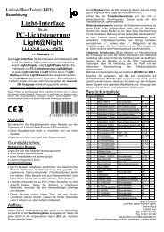
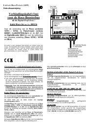
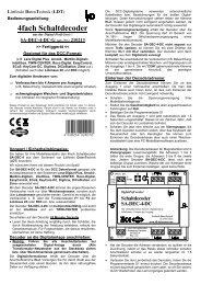
Littfinski DatenTechnik (<strong>LDT</strong>)D-25492 Heist/Germany • Kleiner Ring 9 • www.ldt-infocenter.comTHREE-ASPECTS SIGNALS WITHOUT NUMERIC SIGNThe second sample connection shows two three-aspect signals withoutlower numeric sign connected to each clamp bar:•Sample Connectionof threeaspectSignalswithout NumericSign (page_136)GN1GE1GE2GNGERT1GE1GE2GN1RT1GNGErotredbraunVon Steuereinheit brownoder BoosterFrom command stationor booster-5V+ge1ge2gn1gn2rt1rt2gngewsS1Krotbr.JLeftKL2KL7 KL6 KL5 KL3<strong>Digital</strong>-Profi werden!Lichtsignal-DecoderLS-DEC-NSVorbildgerechtes stellen von 4 Lichtsignalen mitLeuchtdioden. Direkt über Decoderadressen.Littfinski DatenTechnikD-25492 Heistwww.ldt-infocenter.comMulti-<strong>Digital</strong>KL4 KL10 KL9 KL8RightJ1J2J3Prog.Lockwsgegnrt2rt1gn2gn1ge2ge1+5V-AKMM DCC14..18V~A BGEGNRT1GN1GE2GE1GNGERT1GN1GE1GE2Vom ModellbahntrafoFrom transformerThe signals at the left side have been assigned at this sample to thedecoder addresses 1 to 4. The addresses 5 to 8 are assigned to thesignals of the right side. Each signal occupies therefore 2 decoder addresses.All signals can be switched independently.lower signal leftupper signal lefttrain stoptrain stopround / red / - round / red / - round / red / - round / red / -1 2 3 4straight / green / + straight / green / + straight / green / + straight / green / +proceed slow approach proceed slow approachupper signal rightlower signal righttrain stop train stopround / red / - round / red / - round / red / - round / red / -5 6 7 8straight / green / + straight / green / + straight / green / + straight / green / +proceed slow approach proceed slow approachPage 6 / 8<strong>LDT</strong> <strong>Digital</strong>-<strong>Compendium</strong> LS-DEC-NS-001_12_engl
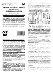
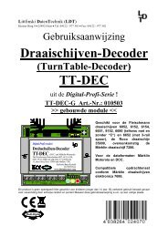
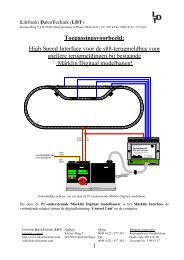
Littfinski DatenTechnik (<strong>LDT</strong>)D-25492 Heist/Germany • Kleiner Ring 9 • www.ldt-infocenter.comTWO-ASPECT SIGNALSOur third sample shows the connection of four two-aspect signals. Twosignals connected to each clamp bar:GN1GE2GNRT1GE2GN1RT1GNrotredbraunVon Steuereinheit brownoder BoosterFrom command stationor booster-5V+ge1ge2gn1gn2rt1rt2gngewsS1Krotbr.JLeftKL2KL7 KL6 KL5 KL3<strong>Digital</strong>-Profi werden!Lichtsignal-DecoderLS-DEC-NSVorbildgerechtes stellen von 4 Lichtsignalen mitLeuchtdioden. Direkt über Decoderadressen.Littfinski DatenTechnikD-25492 Heistwww.ldt-infocenter.comMulti-<strong>Digital</strong>KL4 KL10 KL9 KL8RightJ1J2J3Prog.Lockwsgegnrt2rt1gn2gn1ge2ge1+5V-AKMM DCC14..18V~A BGNRT1GN1GE2GNRT1GN1GE2Vom ModellbahntrafoFrom transformer•Sample Connectionof two-aspectSignals(page_138)The signals at the left side are assigned again to the decoder addresses1 to 4. The addresses 5 to 7 will be occupied by the signals atthe right side. Each signal occupies therefore 1 decoder address. Allsignals can be switched independently.The relevant keys and decoder addresses are indicated at the followingtables:lower signal leftupper signal lefttrain stoptrain stopround / red / - round / red / - round / red / - round / red / -1 2 3 4straight / green / + straight / green / + straight / green / + straight / green / +proceedproceedupper signal rightlower signal righttrain stoptrain stopround / red / - round / red / - round / red / - round / red / -5 6 7 8straight / green / + straight / green / + straight / green / + straight / green / +proceedproceed<strong>LDT</strong> <strong>Digital</strong>-<strong>Compendium</strong> LS-DEC-NS-001_12_engl Page 7 / 8
Littfinski DatenTechnik (<strong>LDT</strong>)D-25492 Heist/Germany • Kleiner Ring 9 • www.ldt-infocenter.comPROGRAMMINGFrom version 4 the Light Signal-Decoder contains a third Jumper (J3)which has to be inserted for programming the unit.The Jumper J3 can be removed after successful programming.This action will protect the memory of the Light Signal-DecoderLS-DEC-NS against overwriting.The assigning (learning) of digital addresses has to be done for eachmodule individually. After activating the decoder programming key S1two light emitting diodes at the left clamp bar will be lighten-up at a 1,5sec. interval. The module has now been set into the learning mode.Now is it required to activate one key of the wanted group of four (1 - 4,5 – 8 etc.) at the command station. The module takes over those fouraddresses and confirms this by flashing the light emitting diodes a littlefaster. By activating again the programming key S1 the two light emittingdiodes will flash at the right clamp bar of the module. Again is it requiredto activate a key of a group of four at the command station. Thedecoder will confirm again the addressing by a faster flashing. The thirdactivation of the programming key S1 will complete the learning process.The addresses are now being stored permanently at the decoderand all signals will be switched automatically to red.•General NoteOur recommendation at this point: Carry out the programming of decoderaddresses before you install the decoder module below your layout.It is obvious that it is much easier to handle the module with all theconnection on a workbench instead overhead below the layout. Aftercompleting the programming please mark the particular module with theassigned digital addresses (e.g. label with pencil letters “5 – 8” for thesecond group of four).A first functional test of the decoder has now already been completed.By an eventual possible malfunction can be some possible failures (e.g.module defect) excluded. After complete assembly of the module at thelayout it would be very difficult to undertake this procedure.ADDITIONAL INFORMATION•Internet:http://www.ldtinfocenter.comAdditional Information about installation and operation of our digitalcomponents and various helpful sample connections are availablewithin our operation instructions, which will be supplied with every moduleand are available at our Internet Site. All shown sample connectionscan be loaded down as PDF-files (e.g. page_173.pdf) and printed at anA4 format.Author: Harry KellnerSubject to technical changes and errors.© 07/2011 by <strong>LDT</strong>Page 8 / 8<strong>LDT</strong> <strong>Digital</strong>-<strong>Compendium</strong> LS-DEC-NS-001_12_engl