Atlas Copco LS Series Cut-Off Overhaul Manual - Jackhammers.com
Atlas Copco LS Series Cut-Off Overhaul Manual - Jackhammers.com
Atlas Copco LS Series Cut-Off Overhaul Manual - Jackhammers.com

You also want an ePaper? Increase the reach of your titles
YUMPU automatically turns print PDFs into web optimized ePapers that Google loves.
<strong>LS</strong> 14, <strong>LS</strong> 16ContentsContentsEnglish . . . . . . . . . . . . . . . . . . . . . . . . . . . . . . . . . . . . . . . . . . . . . . . . . . . . . . . . . . . . . . . . . . . 4© 2008 <strong>Atlas</strong> <strong>Copco</strong> Construction Tools AB | No. 3392 5153 01 | 2008-01-15
Contents<strong>LS</strong> 14, <strong>LS</strong> 16EnglishContentsAbout the <strong>Overhaul</strong>ing instructions. . . . . . . . . . . . . . . . . . . . . . . . . . . . . . . . . . . . . 5Disassembly - assembly . . . . . . . . . . . . . . . . . . . . . . . . . . . . . . . . . . . . . . . . . . . . . . . . . . . 6© 2008 <strong>Atlas</strong> <strong>Copco</strong> Construction Tools AB | No. 3392 5153 01 | 2008-01-15
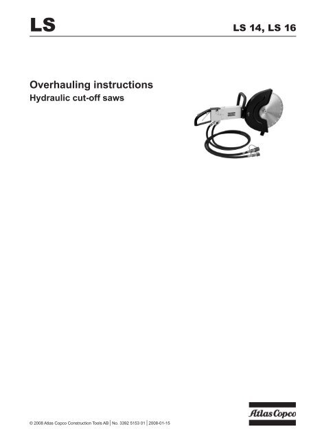
<strong>LS</strong> 14, <strong>LS</strong> 16<strong>Overhaul</strong>ing instructionsAbout the <strong>Overhaul</strong>ing instructionsThe aim of the instructions is to provide you with knowledge of how to make basicoverhauling of the hydraulic cut-off saws <strong>LS</strong> 14 and <strong>LS</strong> 16.Only qualified and trained persons may operate or maintain the cut-off saws. Useonly authorized parts. Any damage or malfunction caused by unauthorized partswill not be covered by the Warranty or Product Liability.For major service to the saws, contact your nearest authorized <strong>Atlas</strong> <strong>Copco</strong>workshop.Safety instructions and technicalspecificationsPlease consult the "Spare parts list" and the "Safety and operating instructions"for the <strong>LS</strong> 14 and <strong>LS</strong> 16 cut-off saws regarding safety instructions and technicalspecifications.© 2008 <strong>Atlas</strong> <strong>Copco</strong> Construction Tools AB | No. 3392 5153 01 | 2008-01-15
<strong>Overhaul</strong>ing instructions<strong>LS</strong> 14, <strong>LS</strong> 16Disassembly - assembly1. <strong>Cut</strong>-off saw4. Disassembly: Unscrew the two insex screwsand remove the guard retainer. Assembly:Mount the guard retainer and the two screws.IMPORTANT: The screw with the hole (forwater flushing) has to be mounted at the top2. Required overhauling tools5. Disassembly: Remove the two screws andthe guard retainer. Remove the guard andthe two nylon washers placed between themotor flange and the guard. Assembly: Mountthe two nylon washers on the motor flange.Place the guard and mount the guard retainerwith the two screws. IMPORTANT: The screwwith the hole (for water flushing) has to bemounted at the top3. Disassembly: Unscrew the counter nut toremove the washer, and unscrew the insexscrew to remove the adapter (if necessary byusing a wheel puller). Be aware of theparallel key. Assembly: Use the reverse order© 2008 <strong>Atlas</strong> <strong>Copco</strong> Construction Tools AB | No. 3392 5153 01 | 2008-01-15
<strong>LS</strong> 14, <strong>LS</strong> 16<strong>Overhaul</strong>ing instructions6. Disassembly: Remove the front handle andthe brake shoe by unscrewing the upperscrew and the clamp screw. Inside the framea fastening plate will drop out (see picture 7)8. Disassembly: Unscrew the lower part ofthe front handle through the frame by usingan insex key. Keep the screw in place andmount a temporary nut M8 to keep the screwin place. By replacement make sure that thescrew does not drop into the frame7. Assembly: Mount the fastening plate with twotemporary screws (the second screw with atemporary nut - see picture 8)9. Front handle and brake shoe© 2008 <strong>Atlas</strong> <strong>Copco</strong> Construction Tools AB | No. 3392 5153 01 | 2008-01-15
<strong>Overhaul</strong>ing instructions<strong>LS</strong> 14, <strong>LS</strong> 1610. Disassembly: Unscrew the four banjo boltsto remove the two banjo elbows.Assembly: Secure the placing of the twoO-rings at each banjo bolt by using grease.Mount all four banjo bolts before tightening13. The hydraulic motor with screws, washer,nuts and the parallel key14. Disassembly. Unscrew the two insexscrews to dismantle the grip <strong>com</strong>plete11. Four banjo bolts, two banjo elbows andeight O-rings. Grease the banjo elbowsbefore assembly15. Grip <strong>com</strong>plete and two insex screws12. Disassembly: Unscrew the two screws atthe motor flange© 2008 <strong>Atlas</strong> <strong>Copco</strong> Construction Tools AB | No. 3392 5153 01 | 2008-01-15
<strong>LS</strong> 14, <strong>LS</strong> 16<strong>Overhaul</strong>ing instructions16. Disassembly: Remove the trigger <strong>com</strong>pleteby pressing a screwdriver to loosen thecirclip. Assembly: Place the trigger in thevalve block and lock with the circlip19. Disassembly: Unscrew the insex screw inorder to be able to remove the water valve.Assembly: Place the water valve and theO-ring in the valve block. Lock the watervalve with the insex screw17. Disassembly: Remove the trigger <strong>com</strong>pleteand the spring for trigger valve. Assembly:Place the trigger <strong>com</strong>plete in the valveblock20. Water valve <strong>com</strong>plete (main parts). Insexlocking screw18. Trigger valve <strong>com</strong>plete (main parts)© 2008 <strong>Atlas</strong> <strong>Copco</strong> Construction Tools AB | No. 3392 5153 01 | 2008-01-15
<strong>Overhaul</strong>ing instructions<strong>LS</strong> 14, <strong>LS</strong> 1621. Disassembly: Unscrew the six insexbushings to separate the valve block fromthe frame. Assembly: Mount the sixinsex bushings and three inside screws tomount the valve block and frame (max.torque = 20 Nm, as they are easy toovertighten)23. Disassembly: Remove the check valvefrom the valve block (where the banjoelbow is mounted). Assembly: Place thecheck valve, where the banjo elbow ismounted, with the smallest diameter of thecheck valve at the lowest position22. Disassembly: Remove the valve block fromthe frame. Assembly: Place three O-ringsand grease in the valve block or grease thetube ends to ensure easy fit of tubes.Make sure that the three tubes are placedcorrectly24. Disassembled cut-off saw (main parts)10© 2008 <strong>Atlas</strong> <strong>Copco</strong> Construction Tools AB | No. 3392 5153 01 | 2008-01-15
Any unauthorized use or copying of the contents or any part thereof is prohibited.This applies in particular to trademarks, model denominations, part numbers anddrawings.© 2008 <strong>Atlas</strong> <strong>Copco</strong> Construction Tools AB, Stockholm, Sweden | No. 3392 5153 01 | 2008-01-15www.atlascopco.<strong>com</strong>