Atlas Copco LP 13-20 Hydraulic Power Pack Safe Operation Manual
Atlas Copco LP 13-20 Hydraulic Power Pack Safe Operation Manual
Atlas Copco LP 13-20 Hydraulic Power Pack Safe Operation Manual
- No tags were found...

You also want an ePaper? Increase the reach of your titles
YUMPU automatically turns print PDFs into web optimized ePapers that Google loves.
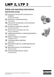
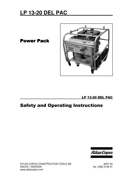
<strong>LP</strong> <strong>13</strong>-<strong>20</strong> DEL PAC ATLAS COPCO CONSTRUCTION TOOLS AB <strong>20</strong>07-03NACKA • SWEDEN No. 3392 5146 01www.atlascopco.com
1 English!"!"INTRODUCTION ....................................................................................................................... 2SAFETY INSTRUCTIONS ........................................................................................................ 2Introduction to safety ....................................................................................................... 2<strong>Safe</strong>ty symbols used ........................................................................................................ 2General safety rules.......................................................................................................... 3Protective equipment........................................................................................................ 3MARKINGS ............................................................................................................................... 4Identification...................................................................................................................... 4CE ....................................................................................................................................... 4<strong>Safe</strong>ty signs on the <strong>Power</strong> <strong>Pack</strong>...................................................................................... 4GENERAL INFORMATION....................................................................................................... 4Parts identification............................................................................................................ 5OPERATING INSTRUCTIONS ................................................................................................. 6Preparation before starting.............................................................................................. 6Starting the engine (electric start)................................................................................... 7Starting the engine (recoil start)...................................................................................... 7Stopping the engine.......................................................................................................... 7<strong>Hydraulic</strong> control and connectors................................................................................... 8Connecting/disconnecting hoses ................................................................................... 8How to check the hydraulic system ................................................................................ 9Service schedules............................................................................................................. 9Scrapping and waste disposal ...................................................................................... 10TROUBLESHOOTING ............................................................................................................ 11TECHNICAL DATA................................................................................................................. 12
English 2!"#$"!These operating and safety instructions must be read before operating the machine. Instructionsfor operation and basic maintenance are included. The purpose of this booklet is to givethe machine user an understanding of how to safely and efficiently use and maintain the machine.%"&!"#$"! SAFETY INSTRUCTIONS• Before starting, read all instructionscarefully• Special attention must bepaid to informationalongside this symbol• Only use <strong>Atlas</strong> <strong>Copco</strong> genuine partsTo reduce the risk of serious injury to yourself or others, read these safety instructions beforeusing the <strong>Power</strong> <strong>Pack</strong>. Post these safety instructions at work locations, provide copies to employees,and make sure that everyone reads the safety instructions before using the <strong>Power</strong><strong>Pack</strong>. Comply with all safety regulations.These instructions have been compiled from international safety standards and form part ofthe operating instructions. Signs and decals that are important for your safety and the care ofthe <strong>Power</strong> <strong>Pack</strong> are included with each power pack. Make sure that they are legible. Newdecals can be ordered using the spare parts list.' () The indications DANGER, WARNING and CAUTION, as used in the safety instructions, havethe following meanings:DANGERImmediate hazard whichWILL result in serious orfatal injury if the warning isnot observedWARNINGCAUTIONHazard or hazardousprocedure which COULDresult in serious or fatalinjury if the warning is notobservedHazard or hazardousprocedure which COULDresult in injury or damagedequipment if the warning isnot observed
3 English*) )• The <strong>Power</strong> <strong>Pack</strong> and accessories must only be used for their purpose• Learn how the <strong>Power</strong> <strong>Pack</strong> is switched off in the event of an emergency• Only qualified and trained persons may operate or maintain the <strong>Power</strong> <strong>Pack</strong>• Keep the <strong>Power</strong> <strong>Pack</strong> in a safe place out of the reach of children, locked up• Pay attention and look at what you are doing• Use your common sense• Do not use the <strong>Power</strong> <strong>Pack</strong> when you are tired or under influence of drugs, alcohol oranything else that may influence your vision, reaction or judgement• Never leave the <strong>Power</strong> <strong>Pack</strong> turned on• Avoid lifting a higher weight than that allowed according to your local environmental workingregulations• Regular maintenance is prerequisite for machine safety. Carefully follow the operatinginstructions. Replace damaged and worn components in good time. For major service tothe <strong>Power</strong> <strong>Pack</strong>, contact your nearest authorized workshop. When cleaning mechanicalparts with solvent, make sure to comply with current health and safety regulations andensure sufficient ventilation• Breathing the <strong>Power</strong> <strong>Pack</strong>’s exhaust gases can harm and possibly kill you. Do not start orrun the <strong>Power</strong> <strong>Pack</strong> in enclosed areas, even if the doors and windows are open. Start andrun the <strong>Power</strong> <strong>Pack</strong> outdoors.WARNINGThe engine exhaust from this productcontains chemicals. Thesechemicals could cause cancer, birthdefects or other reproductive harm.Start and run the <strong>Power</strong> <strong>Pack</strong> outdoors.• Explosions and fire can be caused by sparks from the exhaust or the electrical system.Do not use the machine in closed areas with flammable material, vapour or dust.+, ' Always use approved personal protective equipment. Operators and other staff in the proximityareas where work is in progress must as a minimum use the following approved protectiveequipment:• Hearing protectionWhen the <strong>Power</strong> <strong>Pack</strong> is used as a power source for breakers, cut-off saws and similar tools,use the following personal protective equipment:• Protective helmet• <strong>Safe</strong>ty glass with side protection• Respiratory protection when appropriate• Protective gloves• Protective boots
English 4- #.!*The <strong>Atlas</strong> <strong>Copco</strong> <strong>LP</strong> <strong>13</strong>-<strong>20</strong> DEL PAC fulfils all safety regulations in the Directive 98/37/EC.The <strong>Atlas</strong> <strong>Copco</strong> <strong>LP</strong> <strong>13</strong>-<strong>20</strong> DEL PAC does not comply with the regulations in the Directive<strong>20</strong>00/14/EC with regard to noise. The <strong>Atlas</strong> <strong>Copco</strong> <strong>LP</strong> <strong>13</strong>-<strong>20</strong> DEL PAC has therefore no CEmarking. The <strong>Atlas</strong> <strong>Copco</strong> <strong>LP</strong> <strong>13</strong>-<strong>20</strong> DEL PAC is therefore not approved for use on the EUmarket./ *!#!%#- "!The <strong>Atlas</strong> <strong>Copco</strong> <strong>LP</strong> <strong>13</strong>-<strong>20</strong> DEL PAC is a hydraulic <strong>Power</strong> <strong>Pack</strong> designed for operating <strong>Atlas</strong><strong>Copco</strong> hydraulic breakers and other tools.The <strong>Power</strong> <strong>Pack</strong> is fitted with a 10 HP Lombardini, air cooled, 1 cylinder 4-stroke dieselengine with electric start. The flow of the <strong>LP</strong> <strong>13</strong>-<strong>20</strong> DEL PAC is <strong>20</strong> l.p.m.
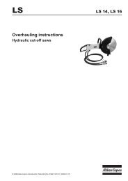
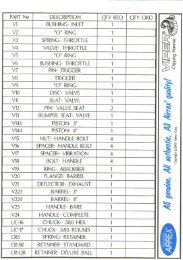
5 English1 Filler cap, fuel 11 <strong>Hydraulic</strong> pump2 Filler cap, hydraulic oil 12 Recoil start3 Sight glass, hydraulic oil level <strong>13</strong> Pressure relief valve4 Filter condition gauge 14 Foldable handles5 <strong>Hydraulic</strong> oil filter 15 By-pass valve6 Engine oil, dipstick 16 Air filter7 Starting switch 17 Drain plug8 Ignition switch OFF and ON 18 Battery9 Stop lever 19 Throttle lever10 Oil cooler
English 6#"!*!"#$"!(The following checks should be made each time you return to the <strong>Power</strong> <strong>Pack</strong> after leaving itfor a period of time. All these checks concern the serviceability of the <strong>Power</strong> <strong>Pack</strong>. Someconcern your safety.• Remove dirt and debris especially from around the linkage and hydraulic oil cooler• Clean all safety decals. Replace any that are missing or cannot be read• Inspect the <strong>Power</strong> <strong>Pack</strong> and hoses generally for signs of damaged and missing parts• Check for fluid and fuel leakages beneath the <strong>Power</strong> <strong>Pack</strong>• Check the security of the hinged frame• Make sure the fuel filler cap is tightly closed• Check the hydraulic oil level and add as necessary• Position the <strong>Power</strong> <strong>Pack</strong> in a safe position• Ensure that the hydraulic couplings are clean and fully serviceable• Ensure that any hydraulic tool you plan to use is compatible with the model of the <strong>Power</strong><strong>Pack</strong> you are using. See the section Flow rates• Check the engine oil level and add oil as necessary• Ensure that you have adequate fuel for the job. Top up as necessary, taking care not tooverfillWARNING• Diesel and its vapours are flammable and explosive. Fire or explosion cancause severe burns or death• Keep naked flames away from the <strong>Power</strong> <strong>Pack</strong>• Do not smoke while refuelling the <strong>Power</strong> <strong>Pack</strong> or working with the engine• Do not refuel with the engine running. Turn off the engine and let the enginecool before refuelling• Do not overfill the tank beyond the top of the red plug inside the fuel tank filter
7 English/)1. Set the hydraulic by-pass valve (A)in the OFF position2. Set the engine speed lever (C) in theSTART position3. Turn the starting key (D) clockwiseto the START position4. Push the start button (E) for a fewseconds5. Remove your hand from the button,as soon as the engine startsCAUTIONIn order not to damage the starter,do not activate the starter for morethan 10 seconds. Wait for about 15seconds before the next try.6. Let the engine warm up without loadfor about 3 minutes/0)1. Set the hydraulic by-pass valve (A)in the OFF position2. Set the engine speed lever (C) in theSTART position3. Take the recoil handle (12) and pullthe rope softly until it is extended toits full limit.4. Let the rope rewind completely.5. Start the engine by pulling the ropestrongly.WARNINGNever use any cold-starting aidssuch as ether, gasoline, paint thinneror other volatile liquid or gas.6. Let the engine warm up without loadfor about 3 minutes/1. Turn the hydraulic by-pass valve (A)to the OFF position2. Move the throttle lever (C) to the lowspeed position and let the enginerun for about 3 minutes without load3. Move the throttle lever (H) to theSTOP position4. Turn the ignition key (D) counterclockwise to the OFF position5. Slowly pull out the recoil startinghandle (12) until resistance is feltand leave the handle in this position.This prevents rust from formingwhile the engine is not in useEHACCAUTIONDo not allow the recoil startinghandle (12) to snap back against theengine. Return it gently to preventdamage to the starter.D
English 8CAUTIONWhen stopping the engine, reducethe load slowly. Do not stop theengine suddenly since it may causethe temperature to rise abnormally.HOffOnGFe1 ))The by-pass valve (F) shall be in the OFFposition when starting and in the ONposition when using the tool.Connectors (G) and (H) are used toconnect the <strong>Power</strong> <strong>Pack</strong> to the tool asfollows:• Connector (G) Return (female)• Connector (H) Feed (male)2/CAUTIONEnsure that any tool you plan to useis compatible with the model of the<strong>Power</strong> <strong>Pack</strong> you are using.Non-compatible tools might harmboth the <strong>Power</strong> <strong>Pack</strong> and the tools.Check the section Flow rates in thisinstruction book and compare theflow rate with the technical specificationsin the instruction book forthe tool.Connecting hoses1. Prepare the <strong>Power</strong> <strong>Pack</strong>a) Turn the by-pass valve to theOFF positionb) Stop the engine2. Inspect the couplingsa) Ensure that the couplings areclean and serviceable3. Connect the hosesa) Attach the return lineb) Attach the feed linec) Rotate the collar on the femalecoupling to secure the coupling4. Check the hydraulic oil levela) Start the engine and run the<strong>Power</strong> <strong>Pack</strong> to fill up the hydrauliccircuitb) Check the hydraulic oil levelDisconnecting hoses1. Prepare the <strong>Power</strong> <strong>Pack</strong>a) Turn the by-pass valve to theOFF positionb) Stop the engine2. Remove the hosesa) Rotate the collar on the femalecouplingb) Release the return linec) Release the feed lineNote: The couplings are unlocked by movingthe collar back on the couplingWARNINGDo not disconnect the hoses whenthe <strong>Power</strong> <strong>Pack</strong> is running or if thehydraulic oil is hot.Hot hydraulic oil might cause seriousburns.
9 English0-250 bar (0-3600 psi)Note: The inaccuracy of the reading on theflow meter is ±2 l.p.m. (±0.5gal/min). If the performance is not inaccordance with the technical specificationsfor the <strong>Power</strong> <strong>Pack</strong>, pleasesee the section TROUBLESHOOTING5-46 l/min. (1-12 gal/min.)1 / // )' To set or check the oil flow and the pressurerelief valve we recommend using the<strong>Atlas</strong> <strong>Copco</strong> test equipment or similar testequipment.+/ )A poorly maintained <strong>Power</strong> <strong>Pack</strong> is a hazard.Doing regular maintenance and lubricationjobs as listed in these schedules willhelp keep the <strong>Power</strong> <strong>Pack</strong> in a safe workingcondition.Apart from the daily jobs, the schedulesare based on the operation hours of the<strong>Power</strong> <strong>Pack</strong>. Keep a regular check ofhours in use. Do not use a <strong>Power</strong> <strong>Pack</strong>that is due for regular service. Rectify anydefects found during regular maintenancebefore clearing the <strong>Power</strong> <strong>Pack</strong> for use.Part number 3371 8011 54How to check1. Stop the engine (see the sectionStopping the engine)2. Connect the test equipment to the<strong>Power</strong> <strong>Pack</strong>. Male (B) to the returnconnection and female (A) to thefeed connection on the <strong>Power</strong> <strong>Pack</strong>.Make sure that the loading valve ofthe test equipment is fully open3. Start the engine (see the sectionStarting the engine – electricstart)4. Move the by-pass valve on the<strong>Power</strong> <strong>Pack</strong> to the ON position5. Turn the loading valve, until thegauge shows approx. 70 bar (1000psi) and allow the <strong>Power</strong> <strong>Pack</strong> towarm up for 3-4 minutesDailyWARNINGMaintenance must be done only bysuitably qualified and competentpersons.Before doing any maintenance,make sure that the <strong>Power</strong> <strong>Pack</strong> issafe and correctly sited on levelground.1. Clean the <strong>Power</strong> <strong>Pack</strong> in general2. Check fuel lines, tank, fuel cap andfittings for cracks or leaks. Replace ifnecessary3. Check for damages4. Check hydraulic fluid level5. Check engine oil level6. Check hydraulic couplings7. Check hydraulic hoses8. Check hydraulic oil filter6. Slowly close the loading valve untilthe pressure gauge shows thenominal pressure according to thetechnical specifications7. Check that the flow is according tothe flow rate in the technical specifications
English 10IMPORTANTWhen the filter gauge needle remainsin the red sector (while theengine is running idle and the oil isservice warm), the filter must bereplaced. The old filter is removedby turning it clockwise (use a filterstrap wrench if necessary). Tiltingthe <strong>Power</strong> <strong>Pack</strong> rearwards willminimise oil spilling.Before mounting the new filter, it isrecommended to grease the surfaceof the seal with oil in order to easecorrect tightening of the filter.Every 3 months1. Do the daily jobs2. Check tightness of nuts, bolts,screws and hose fittings3. Clean the air cleaner element (seeengine manufacturer’s handbook)Every 300 hours or every year1. Do the daily jobs and jobs every 3months2. Change the hydraulic oil3. Change the hydraulic oil filter )WARNINGFine jets of hydraulic oil at highpressure can penetrate the skin. Donot use your fingers to check forhydraulic oil leaks. Do not put yourface close to suspected leaks. Holda piece of cardboard close to suspectedleaks and then inspect thecardboard for signs of hydraulic oil.If hydraulic oil penetrates your skin,get medical help quickly.Used and worn out parts must be treatedand disposed of in such a way that thegreatest possible part of them can be recycledand the influence on the environmentkept as low as possibleNote: Check tightness of nuts, bolts,screws and hose fittings after thefirst days of operation and thereafterin accordance with the maintenancescheduleNote: The engine oil should be replacedafter the first 8 hours of operationand thereafter in accordance withthe maintenance schedule in theengine manufacturer’s operating andmaintenance instructions
11 English"#$31"!*WARNINGMaintenance must be done only by suitably qualified and competent persons.Problem Cause SolutionEngine turns over but doesnot startEngine does not turn overor is difficult to turnLow hydraulic oil levelPoor tool performanceNo fuelFuel line blockedFuel filter is tapedEngine malfunctionBy-pass valve in the ONpositionEngine malfunctionBattery unchargedDamaged hosesLeaking connectionsDefect hose couplingsLow pressure relief valvesettingHigh back pressureWorn hydraulic pumpTop up tankClear lineChange the fuel filterRefer to engine manualTurn valve to OFFRefer to engine manualStart engine with recoil startor recharge batteryCheck and replace if neededCheck for tightness/leaksReplace couplingsAdjust valveCheck hose system forblockageReplace pump
English 12Problem Cause SolutionFrothy or creamy colouredhydraulic oilTool runs hotAir or water in oilPoor siting of <strong>Power</strong> <strong>Pack</strong>causing warm air torecirculateBlocked oil coolerDefect fanBack pressure too highTool defectCheck for loose connectionson line to pumpMake sure that the filler capon the tank is not looseCheck that oil level is at thetop of the sight glassResite <strong>Power</strong> <strong>Pack</strong> for freeair circulationBlow cooler clean. NEVERuse a wire brushReplace fanCheck hose systemCheck and service tool<strong>Power</strong> <strong>Pack</strong> stops suddenly Out of fuel Top up tank"1!"DimensionsEngine typeEngine Lombardini, air cooled, 1cylinder 4-stroke dieselengine with electric startPerformance 10 HP (7.5 kW) at 3600 rpmFuelStarterDieselElectric start and recoil handstart<strong>Hydraulic</strong> systemHeight (A) 705 mm (27.7”)Width (B) 600 mm (23.6”)Length (C) 745 mm (29.3”)Weight with oil 116 kg (256 lbs)Circuit typePump typeFiltrationCoolingsystemOpen centreGear pump, directly drivenfrom the engine crankshaftby means of a flexiblecoupling25µ filter in return line. Filterby-pass valve in valve blockThermostatically controlledair blast oil cooler
<strong>13</strong> EnglishFluids, lubricants, capacity andspecificationItem Capacity Fluid/lubricantEngine (oil)Litres (gal,US)Refer to manufacturer’s operatingand maintenance instructions.Fuel tank 5 (1) Diesel, cetan valuemore than 45<strong>Hydraulic</strong> fluid 7 (1.85) Mobil EAL 224or similarFlow ratesThe European <strong>Hydraulic</strong> Tool ManufacturersAssociation (E.H.T.M.A.) has categorisedhydraulic power packs and tools interms of flow rate and working pressure.IMPORTANTThe torque of the engine is reducedwhen reducing the rpm. The <strong>Power</strong><strong>Pack</strong> can therefore not in all casesdeliver the maximum pressure atlow rpm.Hose length1 In normal ambient temperature, 0-40°C (32-104°F), the maximum hoselength should not exceed 25 m (82 ft)2 Normally, 7 m of Twin hoses are to beused for the <strong>Power</strong> <strong>Pack</strong>.Twin hose and other accessories areshown in the spare parts list.Our <strong>LP</strong> <strong>13</strong>-<strong>20</strong> DEL PAC is categorised bythe E.H.T.M.A. as below:Flow rate, l.p.m. (gal,US) <strong>20</strong> (5)Nominal pressure, bar (psi) 1<strong>20</strong> (1800)Max. pressure, bar (psi) 140 (<strong>20</strong>00)E.H.T.M.A. category CNote: <strong>Atlas</strong> <strong>Copco</strong> hydraulic powerpacks are clearly marked withE.H.T.M.A. categories. It is importantthat any tool used with the<strong>Power</strong> <strong>Pack</strong> is of a compatiblecategory. If any doubt, consultyour <strong>Atlas</strong> <strong>Copco</strong> dealer.WARNINGThe setting of the pressure reliefvalve on the <strong>Power</strong> <strong>Pack</strong> can insome cases be higher than the prescribedmax. pressure according tothe E.H.T.M.A. category.A too high pressure relief valve settingcan harm the tool.Readjust the pressure relief valveon the <strong>Power</strong> <strong>Pack</strong> if the technicalspecifications of the tool prescribea lower pressure relief valve settingthan the standard setting of the<strong>Power</strong> <strong>Pack</strong>.