Swing cylinders - Enerpac
Swing cylinders - Enerpac
Swing cylinders - Enerpac

You also want an ePaper? Increase the reach of your titles
YUMPU automatically turns print PDFs into web optimized ePapers that Google loves.
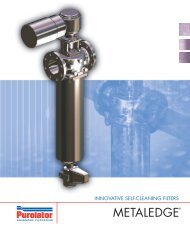
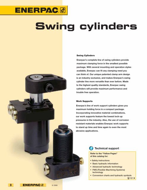
<strong>Swing</strong> <strong>cylinders</strong><strong>Swing</strong> Cylinders<strong>Enerpac</strong>’s complete line of swing <strong>cylinders</strong> providemaximum clamping force in the smallest possiblepackage. With several mounting and operation stylesavailable, <strong>Enerpac</strong> can fit any clamping need youcan think of. Our unique patented clamp arm designis an industry exclusive, and makes <strong>Enerpac</strong>’s swingcylinder line more versatile than ever before. Madeto the highest quality standards, <strong>Enerpac</strong> swing<strong>cylinders</strong> will provide maximum performance andtrouble free operation.Work Supports<strong>Enerpac</strong>’s line of work support <strong>cylinders</strong> gives youmaximum holding force in a compact package.Incorporating innovative material combinations,our work supports feature the lowest lock-uppressures in the industry. Also, the use of corrosionresistant materials enables <strong>Enerpac</strong> work supportsto stand up time and time again to even the mostabrasive applications.Technical supportRefer to the “Yellow Pages”of this catalog for:• Safety instructions• Basic hydraulic information• Advanced hydraulic technology• FMS (Flexible Machining Systems)technology• Conversion charts and hydraulic symbols161 8 © 2008www.enerpac.com
& Work supports▼ series▼ page<strong>Swing</strong> cylinder range overview10 - 11Upper flange swing <strong>cylinders</strong>SU10 12 - 13 11Lower flange swing <strong>cylinders</strong>SL14 - 15Threaded body swing <strong>cylinders</strong>ST16 - 17Cartridge model swing <strong>cylinders</strong>SC18 - 19Additional swing <strong>cylinders</strong>SC, ASCWTR20 - 23Positive locking swing <strong>cylinders</strong> [Collet-Lok ® ]WP24 - 25Clamp armsCA26 - 27Pivoting T-armsCACCAPT28 - 29Upreach clamp armsCAU30 - 31Work support range overview32 - 33Hydraulic advance work supportsWF34 - 35Spring advance work supportsWS36 - 37Positive locking work supports [Collet-Lok ® ]WP38 - 39ABWork support mounting dimensionsWF, WS40 - 41DC© 2008 9
<strong>Swing</strong> <strong>cylinders</strong> Application & selection<strong>Swing</strong> <strong>cylinders</strong>Work supports98-037Shown: SCRD-122, STLD-21, WPFL-50Compact and full featured design• Compact design allows for efficient fixture layout• Variety of mounting styles to meet design needs• Double and single-acting <strong>cylinders</strong> to suit a varietyof hydraulic requirements• Choice of porting styles to meet system anddesign requirements• All <strong>cylinders</strong> are available as left and right turning models• Large ball and cam design on 21, 51 and 121 models allowsswing rotation to be changed easily• Kick-out mechanism on 92, 201, and 351 models preventsdamage to cylinder from high flow rates or misapplication<strong>Enerpac</strong> swing <strong>cylinders</strong> allow unobstructedpart fixturing and placement. The plunger rod andthe attached clamp arm rotate 90 degrees in either aclockwise or counter-clockwise direction, then traveldown an additional distance to clamp against thefixtured part. Upon release of clamping pressure,the clamp arm rotates back 90 degrees in theopposite direction to allow for part removaland new part placement.Roller in groove• Double index provides low heightdesign to minimize fixture height• Overload clutch allows clamp todisengage if needed to preventdamage due to improperpart loadingBall in groove• Rotation direction can be changedon-site to reduce spare inventoryby 2/3 (67%)• Ball and cam rotation ensuressmooth accurate operationSelect your swing cylinder type:Single acting• The obvious choice when thereare few system restrictions, andthere are not many units retractingsimultaneously• Fewer valving requirements whichresults in a less complex circuit• Innovative clamp arm design allowsquick and secure arm positioningDouble acting• Used when greater control is requiredduring the unclamp cycle• When timing sequences are critical:less sensitive to system backpressures, resulting from long tubelengths or numerous componentsbeing retracted at the same time• Innovative clamp arm design allowsquick and secure arm positioning❚ <strong>Swing</strong> <strong>cylinders</strong> used in conjunction with work supportsand other <strong>Enerpac</strong> components to positively hold theworkpieces during machining operations.Collet-Lok ® positive locking• <strong>Enerpac</strong> Collet-Lok ® positivelocking <strong>cylinders</strong> are designed tomechanically hold the workpiecewhile hydraulic pressure is removed.After machining, hydraulic pressureis applied to unclamp the workpiece• Used when live hydraulics are notavailable during the clamp cycle orwhen parts must be held for longperiods of time• This design is an industry exclusive98-001For Collet-Lok ® positive lockingswing <strong>cylinders</strong>, see 24 10© 2008www.enerpac.com
<strong>Swing</strong> <strong>cylinders</strong> - Threaded body models<strong>Swing</strong> <strong>cylinders</strong>Work supportsShown: STRD-51, STRD-201Cylinders can be threaded directly into fixture…can be secured at any height• Body thread for precise cylinder height positioning• Threaded port connection• Easy installation and removal• Greatest flexibility in fixture design• 30, 45 and 60 degree swing angles available on request98-040ST series<strong>Enerpac</strong> threaded body swing<strong>cylinders</strong> are threaded directly intothe fixture.The cylinder height is adjusted tothe appropriate height, and thenlocked in place using a flangenut ( 78).SAE oil connectionFlange nutProduct selectionClamping Stroke Left Right Cylinder Oil Max. Standardforce 1) turning turning effective area capacity oil clamp arm90° 90°flow 1)in in 2 in 3 SoldUn- Un- separatelylbs Clamp Total Clamp clamp Clamp clamp in 3 /min 26 ▼ Single acting Model number 2)475 .32 .65 STLS-21 STRS-21 .12 – .08 – 12 CAS-211100 .39 .89 STLS-51 STRS-51 .28 – .25 – 25 CAS-511800 .47 .87 STLS-92 STRS-92 .49 – .42 – 60 CAS-922400 .50 1.12 STLS-121 STRS-121 .63 – .70 – 100 CAS-1213900 .55 1.10 STLS-201 STRS-201 1.10 – 1.22 – 140 CAS-2017450 .63 1.18 STLS-351 STRS-351 1.92 – 2.27 – 240 CAS-351▼ Double acting Model number 2)500 .32 .65 STLD-21 STRD-21 .12 .24 .08 .15 12 CAS-211250 .39 .89 STLD-51 STRD-51 .28 .59 .25 .52 25 CAS-512025 .47 .87 STLD-92 STRD-92 .49 1.25 .42 1.08 60 CAS-922600 .50 1.12 STLD-121 STRD-121 .63 1.23 .70 1.40 100 CAS-1214200 .55 1.10 STLD-201 STRD-201 1.10 2.35 1.22 2.60 140 CAS-2017600 .63 1.18 STLD-351 STRD-351 1.92 3.68 2.27 4.35 240 CAS-3511)With standard clamp arm. Clamp arms are sold separately ( 26). Clamping forcesfor single-acting models are reduced in order to overcome return spring force.2)For models with straight plunger movement, replace L or R with S.Note: Call <strong>Enerpac</strong> to ordermodels with BSPPport connections.98-014❚ Threaded body swing <strong>cylinders</strong>allow the clamp to be buriedin the fixture to minimize therequired area, while the heightremains adjustable.LeftturningmodelsDimensions in inches [ ]▼ Single actingA B C C1 C2 D D1 D2 F H J1ØØSTLS-21 4.41 2.32 1.04 1.69 .98 1.125-16 UNF 1.55 1.30 .39 .39 2.09STLS-51 5.31 2.71 1.08 1.97 .98 1.375-18 UNF 1.87 1.50 .63 .38 2.60STLS-92 5.67 3.20 1.30 2.17 1.18 M48 x 1,5 2.46 1.89 .98 .51 1.69STLS-121 6.75 3.37 1.06 2.18 1.00 1.875-16 UNF 2.38 2.00 .87 .38 3.38STLS-201 6.57 3.74 1.38 2.48 1.26 2.500-16 UNF 2.99 2.56 1.26 .51 2.06STLS-351 7.46 4.24 1.38 2.56 1.27 3.125-16 UNF 3.48 3.15 1.50 .51 2.57▼ Double actingSTLD-21 4.41 2.32 1.04 1.69 .98 1.125-16 UNF 1.55 1.30 .39 .39 2.09STLD-51 5.31 2.71 1.08 1.97 .98 1.375-18 UNF 1.87 1.50 .63 .38 2.60STLD-92 5.67 3.20 1.30 2.17 1.18 M48 x 1,5 2.46 1.89 .98 .51 1.69STLD-121 6.75 3.37 1.06 2.18 1.00 1.875-16 UNF 2.38 2.00 .87 .38 3.38STLD-201 6.57 3.74 1.38 2.48 1.26 2.500-16 UNF 2.99 2.56 1.26 .51 2.06STLD-351 7.46 4.24 1.38 2.56 1.27 3.125-16 UNF 3.48 3.15 1.50 .51 2.57NOTE: dimensions shown with standard clamp arm.16© 2008www.enerpac.com
Dimensions & optionsST seriesABAccessory ChartModel Nos. Mounting FlangeLeft Right flange nutturning turningSoldSold90°Separately Separately79 78▼ Single actingSTRS-21 STRS-21 — MF-281 FN-281STRS-51 STRS-51 AW-5 MF-351 FN-351STRS-92 STRS-92 — MF-482 FN-482STRS-121 STRS-121 AW-89 MF-481 FN-481STRS-201 STRS-201 AW-19 MF-651 FN-651STRS-351 STRS-351 AW-90 MF-801 FN-801▼ Double actingSTRD-21 STRD-21 — MF-281 FN-281STRD-51 STRD-51 AW-5 MF-351 FN-351STRD-92 STRD-92 — MF-482 FN-482STRD-121 STRD-121 AW-89 MF-481 FN-481STRD-201 STRD-201 AW-19 MF-651 FN-651STRD-351 STRD-351 AW-90 MF-801 FN-801-21, 51, 121 -92, 201, 35125˚ BD2 50˚AC2J1HAtype 21 SAE #251, 121 SAE #4KQD1= Clamping= Unclamping (venting)FDNPTCBC122,5˚D2 45˚type 92 G1/4"201, 351 SAE #4MKA C2HK M N P Q T WWJ1BAQD1FDNCP TBC1RightturningmodelsSingle acting ▼.63 – .61 .96 .250-20 unc 1.22 – 1.1 STRS-21.75 – .75 1.58 .312-18 unc 1.89 – 2.5 STRS-51.98 .61 .94 1.77 M10 x 1,5 2.20 2.48 4.4 STRS-921.19 – 1.00 2.00 .375-16 unc 2.43 – 3.5 STRS-1211.18 .93 1.28 2.17 .500-13 unc 2.76 2.83 7.1 STRS-2011.58 1.10 1.57 2.68 .625-11 unc 3.27 3.21 12.1 STRS-351Double acting ▼.63 – .61 .96 .250-20 unc 1.22 – 1.1 STRD-21.75 – .75 1.58 .312-18 unc 1.89 – 2.5 STRD-51.98 – .94 1.77 M10 x 1,5 2.20 2.48 4.4 STRD-921.19 – 1.00 2.00 .375-16 unc 2.43 – 3.5 STRD-1211.18 – 1.28 2.17 .500-13 unc 2.76 2.83 7.7 STRD-2011.58 – 1.57 2.68 .625-11 unc 3.27 3.21 12.1 STRD-351lbsForce: 500 - 7600 lbsStroke: .32 - 1.18 inchPressure: 500 - 5000 psiE Cilindros giratoriosF Vérins de bridage pivotantsD SchwenkspannzylinderOptionsClamp arms26 Work supports32 Collet-Lok ®swing <strong>cylinders</strong>Accessories24 78 Important30, 45, and 60 degreerotations are available uponrequest. Add -30, -45 or -60to end of standard modelnumber to order directlyfrom <strong>Enerpac</strong>. To orderrotation limiter separately,see page 26.Custom <strong>cylinders</strong> includinglonger stroke lengths areavailable on request.In case there is a risk ofmachining coolants anddebris being inhaled viathe breather vent, it isrecommended to pipe thisport to an area outside thefixture that is protectedfrom machining coolantsand debris.Do not exceedmaximum flow rates.<strong>Swing</strong> <strong>cylinders</strong>Work supportsLinear <strong>cylinders</strong> Power sources Valves SystemcomponentsYellow pages© 2008 17
<strong>Swing</strong> <strong>cylinders</strong> - Cartridge models<strong>Swing</strong> <strong>cylinders</strong>Work supportsShown: SCRD-122, SCRD-52Eliminates the need for tubing and fittings… <strong>cylinders</strong> can be designed into narrow fixture platesas thru-hole mounting is fully functional• Minimal space required on fixture• Can be completely recessed in fixture• External plumbing not required• Allows close positioning of adjoining units• 30, 45 and 60 degree swing angles available on request98-041<strong>Enerpac</strong> compact design cartridge model swing <strong>cylinders</strong> used in conjunctionwith a cartridge model work support in a typical clamping application.SC series<strong>Enerpac</strong> cartridge swing <strong>cylinders</strong>are designed for integratedmanifold mounting. This eliminatesthe need for fittings and tubing onthe fixture.Cartridge swing <strong>cylinders</strong> simplifymounting and optimize clampingeffectiveness.❚ Hydraulic fixture with componentson two faces for more efficientproduction.Product selectionClamping Stroke Left Right Cylinder Oil Max. Standardforce 1) turning turning effective area capacity oil clamp armflow 1)in in 2 in 3 Sold90°Un- Un- separatelylbs Clamp Total Clamp clamp Clamp clamp in 3 /min 26 ▼ Single acting Model number 2)475 .32 .65 SCLS-22 SCRS-22 .12 - .08 - 12 CAS-211100 .39 .89 SCLS-52 SCRS-52 .28 - .25 - 25 CAS-512400 .50 1.12 SCLS-122 SCRS-122 .63 - .70 - 100 CAS-121▼ Double acting Model number 2)500 .32 .65 SCLD-22 SCRD-22 .12 .24 .08 .15 12 CAS-211250 .39 .89 SCLD-52 SCRD-52 .28 .59 .25 .52 25 CAS-512600 .50 1.12 SCLD-122 SCRD-122 .63 1.23 .70 1.40 100 CAS-1211)With standard clamp arm. Clamp arms are sold separately ( 26). Clamping forces for single-acting models arereduced in order to overcome return spring force.2)For models with straight plunger movement, replace L or R with S.30007-4LeftturningmodelsDimensions in inches [ ]▼ Single actingA B C C1 C2 D1 D2 E FhexagonSCLS-22 4.41 2.18 .90 1.55 .84 1.50 1.00 1.38 .39SCLS-52 5.31 3.13 1.49 2.25 1.27 2.25 1.37 2.00 .63SCLS-122 6.75 3.69 1.38 2.50 1.32 3.00 2.25 2.75 .87▼ Double actingSCLD-22 4.41 2.18 .90 1.55 .84 1.50 1.00 1.38 .39SCLD-52 5.31 3.00 1.36 2.25 1.27 2.25 1.37 2.00 .63SCLD-122 6.75 3.69 1.38 2.50 1.32 3.00 2.25 2.75 .87NOTE: dimensions shown with standard clamp arm.ØØ18© 2008www.enerpac.com
Dimensions & optionsSC seriesInstallation dimensionsin inches-22 modelsForce: 475 - 2600 lbsStroke: .65 - 1.12 inchPressure: 500 - 5000 psi<strong>Swing</strong> <strong>cylinders</strong>Work supports-22, 52, 122 modelsED1QøFC2AJ1WøD2øJPKCTBC11.88 min.**2.00 min.**1.62 min.**1.07-1.43-52 models1.19-1.62-122 models1.18-1.20.62-.65.57-.59.54-.56ø.07-.09.08-.10ø.18-.20.11-.13ø.18-.20.15-.17ø1.51-1.53ø1.19-1.21M28 x 1,5.05-.07R and Blend* Minimum plate height for single-acting models.** Minimum plate height for double-acting models.30˚6320˚ø1.06-1.08ø2.26-2.28ø1.67-1.69M42 x 1,530˚6320˚ø1.40-1.42ø3.01-3.03ø2.38-2.40M60 x 1,530˚6320˚ø2.30-2.3263.05-.07.12 maxø1.000-1.00263.05-.07.12 max.08-.10ø1.375-1.37763.05-.07.12 max.08-.10ø2.250-2.252.68-.701.00 min.*.70-.741.00 min.*.64-.681.00 min.*E Cilindros giratoriosF Vérins de bridage pivotantsD SchwenkspannzylinderOptionsClamp armsAccessories26 Work supports32 Collet-Lok ®swing <strong>cylinders</strong>Sequencevalves24 78 136 Important30, 45, and 60 degreerotations are available uponrequest. Add -30, -45 or -60to end of standard modelnumber to order directlyfrom <strong>Enerpac</strong>. To orderrotation limiter separately,see page 26.Custom <strong>cylinders</strong> includinglonger stroke lengths areavailable on request.Linear <strong>cylinders</strong> Power sources Valves SystemcomponentsYellow pagesJ J1 K P Q T WRightturninglbs modelsSingle acting ▼M28 x 1,5 .59 .63 .96 .250-20 UNC 1.22 2.23 1.0 SCRS-22M42 x 1,5 .66 .75 1.58 .312-18 UNC 1.89 2.31 2.0 SCRS-52M60 x 1,5 .62 1.19 2.00 .375-16 UNC 2.43 2.94 5.5 SCRS-122Double acting ▼M28 x 1,5 .59 .63 .96 .250-20 UNC 1.22 2.23 1.0 SCRD-22M42 x 1,5 .66 .75 1.58 .312-18 UNC 1.89 2.31 2.0 SCRD-52M60 x 1,5 .62 1.19 2.00 .375-16 UNC 2.43 2.96 5.5 SCRD-122In case there is a risk ofmachining coolants anddebris being inhaled viathe breather vent, it isrecommended to pipe thisport to an area outside thefixture that is protectedfrom machining coolantsand debris.Do not exceedmaximum flow rates.© 2008 19
<strong>Swing</strong> <strong>cylinders</strong>SC series<strong>Swing</strong> <strong>cylinders</strong>Work supports99-083Shown: SC-3, SC-1SC seriesThese swing <strong>cylinders</strong> rotate90˚ as they begin their stroke,continuing without rotation for thefinal clamping stroke. Cylinderscan be changed to left swing,right swing, or pull applicationsby loosening the side plug andthen rotating the plunger to adesired position.The SC-1 and SC-3 include aretract spring for single-actingoperation. Both <strong>cylinders</strong> canbe operated as double-acting<strong>cylinders</strong> by connecting a retractline to the vent port.Changeable swing function… with 360° fully adjustable clamp arm• Changeable swing function: clamp armmovement can be adjusted to left or rightswing, or straight pull function• 88-92° clamp arm swing arc• Easy installation: built-in mountingsand brackets• Compact design for use in limitedspace applications• Easy and precise locating of arm forclamp positioning• Single or double-acting <strong>cylinders</strong> to suitvariety of hydraulic requirementsSelection chartClamping Stroke Model Cylinder Oilforce 1) number effective capacityareain in 2 in 3lbs Clamp Total Pull Push Pull Push2164 .50 1.50 SC-1 .98 1.767 1.47 2.65500 .25 .75 SC-3 .245 .442 .184 .3311)With standard clamp arm (included with cylinder).Note: - Long clamps arms can be fabricated by the user.- For long clamp arms, use VFC series flow control valves.Force: 500 - 2100 lbsStroke: .25 - .50 inchPressure: 1500 - 3000 psiE Cilindros giratoriosF Vérins de bridage pivotantsD SchwenkspannzylinderArm Max. Clampinglength pressure forcein psi lbs▼ SC-1– 3000 26402.00 2) 3000 21643.00 3000 19604.00 3000 17405.00 2400 12006.00 2000 840▼ SC-3– 3000 7001.00 2) 3000 5002.00 2000 2502)Standard clamp arm (included).SC-1SC-3.40D1U1.20D1U1PD2UQ90°PD2UQ90°.500-13 UNC.312-24 UNFABGHGF.50G1DH1C1 CWABGHFG1DH1C1 CWModelnumberProduct dimensions in inches [ ]A B C C1 D D1 D2 F G G1 H H1 P Q U U1 WUN NPT NPT UN lbsSC-1 8.88 7.37 5.87 5.74 1.875-16 2.90 1.88 1.00 .250-18 .125-27 3.31 .88 2.00 .38-16 1.28 2.06 2.87 6SC-3 5.27 4.26 3.71 3.48 1.00-12 2.00 1.13 .50 .125-27 .125-27 2.15 .63 1.00 .250-20 .75 1.50 2.03 220© 2008www.enerpac.com
<strong>Swing</strong> clampsASC seriesForce: 1375 - 4375 lbs Adjustable clamping strokeStroke: .25 - .43 inchPressure: 1200 - 2500 psiE Cilindros giratoriosF Vérins de bridage pivotantsD SchwenkspannzylinderELFD… turns clockwise or counter-clockwise• Adjustable bolt in clamp arm for clampingstroke adjustment• Low profile, ideal for limited spaceapplications• Quick swing action allows clamp arm to swingfree of cutter and reclamp after it has passed• 94-100° clamp arm swing arcASC-30, -100Clamping positionCKB94-100˚Rest positionJNAVHUGShown: ASC-30ASC seriesClamping arm rotates 97°clockwise or counter-clockwise(requires easily changed rotationspring) to position itself overthe workpiece. Then, a verticalplunger exerts an upward thruston the back end of the swing armproviding a powerful downwardpressure to clamp the workpiece.ImportantFor high cycle applicationsuse double-acting <strong>cylinders</strong>.<strong>Swing</strong> <strong>cylinders</strong>Work supportsLinear <strong>cylinders</strong> Power sources Valves SystemcomponentsYellow pagesSelection chartCylinder Stroke Model Operating Cylinder Oil Max.capacity number pressure effective capacity oil flowarea❚ View of a machining fixture withASC-30 clamping <strong>cylinders</strong>.lbs in psi in 2 in 3 in 3 /min lbs1375 .25 ASC-30 1200 - 2500 .55 .30 115 64375 .43 ASC-100 1200 - 2500 1.76 1.22 115 18ModelnumberProduct dimensions in inches [ ]A B C D E F G H J K L N U VNPT UN øASC-30 5.00 3.38 .50 .25 3.50 .75 .125-27 2.75 1.63 .500-13 2.75 2.50 2.50 .41ASC-100 7.00 4.50 .53 .43 5.25 .73 .125-27 4.25 2.25 .500-13 4.00 3.50 3.50 .63© 2008 21
Three-position swing cylinder Application & selection<strong>Swing</strong> <strong>cylinders</strong>Work supportsShown: WTR-24Unobstructed part loading• Plunger rotates only when cylinder is fully extended,to minimize obstructions• Ideal for mounting beneath the fixture, as the clampdoes not rotate until the workpiece has been cleared• Stainless steel body for additional corrosion resistance• Three port design for fewer hydraulic connections• Fully threaded body for easy installation• Standard two sided clamp arm included• Clamp arm design makes mounting easy98-043WTR seriesThe three position swing cylinderrotates 90° only after the plungerhas completely extended. Thisfeature allows the clamp to bemounted beneath the workpiece,where the clamp travels throughthe part for clamping.Operation sequenceThe three position swing cylinder is ideal for parts which have a through hole.The clamp allows completely unobstructed part loading.BBBBBBACACACACACACStep 1Pressurizeport A.Plungerextendsthroughworkpiece.Step 2Keep port Apressurized.Pressurizeport C.Plungermakes 90° flatrotation.Step 3Keep port Cpressurized.Pressurizeport B.Plungerretracts:clamp forceis applied.Step 4Keep port Cpressurized.Pressurizeport A.Plungerextends:clamp forceis released.Step 5Keep port Apressurized.Depressurizeport C.Plungermakes 90° flatrotation.Step 6Pressurizeport B.Plungerretractsthroughworkpiece.Selection chartClamping Stroke Model Cylinder Oil capacity Max. Maximumforce 1) number 2) effective oil flow cycle ratearea22in 2 in 3 cycleslbs in Clamp. Unclamp. Clamp. Unclamp. in 3 /min /min5000 2.50 WTR-24* .98 1.77 2.5 4.4 116 41)When using optional CA-28 clamp arm, max. operating pressure is 2000 psi.2)Standard clamp arm included.* This product is made to order. Please contact <strong>Enerpac</strong> for delivery information before specifying in your design.
Dimensions & optionsWTR seriesWTR-24Force: 1960 - 5000 lb1.25Stroke: 2.50 inchPressure: 2000 - 5000 psi<strong>Swing</strong> <strong>cylinders</strong>Work supports11.318.811.00BA = AdvanceB = RetractC = Rotate 90°2.382 3 /4"-16UNCø 1.00A4.62SAE #47.75E Cilindros giratoriosF Vérins de bridage pivotantsD Schwenkspannzylinder321OptionsHigh pressurefiltersFittingsValves157 158 122 ImportantIt is highly recommended thatsystem filtration be used toensure reliable operation.Linear <strong>cylinders</strong> Power sources Valves SystemcomponentsDo not exceed maximumpressure and flow rates.Yellow pagesOptional CA-28 clamp armThe WTR-24 has a two-sided standard clamp arm included. The CA-28 clamparm can be used to secure the workpiece on one side only, though the clampingpressure must be reduced to 2000 psi maximum.For recommended valvingschemes, please refer to our“Yellow pages”Clamp arm movement:90° ± 3° flat rotation.161 15 /16"-20 UNEFClampingstroke5 /16"-20 UNF1.00.501.251.192.253.8598-044b5 /16"-24 UNFwww.enerpac.com© 2008 23
<strong>Swing</strong> <strong>cylinders</strong> - Collet-Lok ® design<strong>Swing</strong> <strong>cylinders</strong>Work supportsShown: WPFR-100, WPTR-100Ideal when live hydraulics are not available… clamping is maintained mechanically so live hydraulicsare not required during the machining cycle• Double acting Collet-Lok ® action allows fully automated operation• Additional level of safety since live hydraulics are not required to maintainclamping force• Collet-Lok ® swing <strong>cylinders</strong> can be mounted by the flange, or threaded into thefixture. Flanged models for manifold mount are available as a custom option.98-004 98-042❚ Lower flange Collet-Lok ® swingcylinder mounted on a pallet.24WP series<strong>Enerpac</strong> Collet-Lok ® <strong>cylinders</strong> aredesigned to mechanically hold theworkpiece after hydraulic pressureis removed. Clamping capacitiesrange from 1000 lbs. to 8500 lbs.SAE oil connectionFlange nutColletWedgeHydraulic pressure pushes thecollet up a wedge, locking theplunger in the clamping position.Selection chartClamping Stroke Left Right Cylinder Oil Max. Standardforce 1) turning turning effective area capacity oil clamp armflow 1)in in 2 in 3 Sold90°Un- Un- separatelylbs Clamp Total Clamp clamp Clamp clamp in 3 /min 26 ▼ Lower flange4321Model number1000 .32 .94 WPFL-50 WPFR-50 .25 .71 .24 .67 122 CA-5402000 .47 1.10 WPFL-100 WPFR-100 .50 1.11 .55 1.22 305 CA-10508500 .39 1.65 WPFL-300* WPFR-300* 2.05 3.45 3.40 5.70 600 CA-3070▼ Threaded bodyModel number2000 .47 1.10 WPTL-100 WPTR-100 .50 1.11 .55 1.22 305 CA-10508500 .39 1.65 WPTL-300* WPTR-300* 2.05 3.45 3.40 5.70 600 CA-30701)Using standard clamparm. Clamp arms are soldseparately ( 26).LeftturningmodelsCollet-Lok ® sequenceStep 1Pressurize port #1.Plunger turns 90°and clamps part.Product dimensions in inches [ ]▼ Lower flangeNote: - Call <strong>Enerpac</strong> for models with metric thread and BSPP port connections.- Mini mum working pressure for Collet-Lok ® system is 1400 psi.* This product is made to order. Please contact <strong>Enerpac</strong> for delivery information beforespecifying in your design.4321Step 2Keep port #1pressurized.Pressurize port #2.Plunger will belocked in clampedposition.▼ Threaded bodyWPTL-100 8.39 7.29 3.68 3.56 1.875-16 un 2.76 .88 1.24 2.63 2.96WPTL-300* 12.21 10.55 4.78 4.53 3.125-16 un 3.66 1.38 1.50 3.60 3.96Note: Dimensions shown with standard clamp arm.* This product is made to order. Please contact <strong>Enerpac</strong> for delivery information before specifying in your design.4321Step 3Depressurizeport #1 and #2.Uncouple cylinderfrom hydraulicpower source.Part will be held inplace.4321Step 4Pressurizeport #3.Plunger will beunlocked andthe clamp forcereleased.A B C C1 D D1 F H1 H2 H3Ø Ø ØWPFL-50 7.91 6.97 5.79 .98 2.28 3.35 .75 .39 .50 –WPFL-100 8.78 7.68 6.50 .98 2.68 3.94 .88 .39 .50 –WPFL-300* 12.63 11.02 9.17 .98 3.54 5.19 1.38 .43 .50 –4321Step 5Keep port #3pressurized.Pressurizeport #4.Plunger will extendand turn to itsoriginal position.www.enerpac.com
Dimensions & optionsWP seriesABInstallation dimensionsin inchesClamping Fixture Mounting Minimumforce 1) hole thread depthlbs Ø D3 J mm J2▼ Lower flange1000 2.301 ±.012 M6 x 1,00 .682000 2.701 ±.012 M8 x 1,25 .728500 3.565 ±.012 M10 x 1,50 .72Clamping Fixture Mounting Mountingforce 1) hole flange nutSold Soldseparately separatelylbs Ø D3 79 78 ▼ Threaded body2000 1.875-16 un MF-481 FN-4818500 3.125-16 un MF-801 FN-8011)With standard clamp arm.WPF models WPT modelsH230˚60˚(6x)J1260˚(3x)31øJøFøDTPVQKCW UABH3H2J1H1øD332øJøFJ4 1C1øD1H1øDX XSAE #44SAE #2øD1J2Oil port functions1 90° Rotation and clamp2 Locks system3 Unlocks system4 Unclamp and 90° rotationTPX = 45° WPT-100 modelsX = 30° WPT-300 modelsJ J1 K L P Q T U V WUN UN lbsQC1L324 1øD3KCWFlange NutRightturningmodelsLower flange ▼.625-18 .31 1.18 – 1.57 .312-18 2.13 2.76 .35 .55 5.1 WPFR-50.750-16 .35 1.18 – 1.97 .375-24 2.52 3.31 .35 .55 7.7 WPFR-1001.250-12 .39 1.85 – 2.76 .625-18 3.66 4.41 .43 .55 26.5 WPFR-300*Threaded body ▼.750-16 .35 1.18 1.63 1.97 .375-24 2.52 – – 1.18 6.6 WPTR-1001.250-12 .39 1.85 3.35 2.76 .625-18 3.66 – – 1.18 24.2 WPTR-300*E Cilindros giratoriosF Vérins de bridage pivotantsD Schwenkspannzylinder3214Stroke: .94 - 1.65 inchPressure: 1400 - 5000 psiCustom Options AvailableIntermediatecapacitiesManifold mounting60°Options26 38 136 78 Different flangelocations60°Flexible Machining SystemsSee Yellow Pages ( 184)Clamp armsCollet-Lok ®work supportsSequencevalvesForce: 1000 - 8500 lbsAccessoriesImportantMinimum unlock pressuremust be at least 1500 psiabove lock pressure.<strong>Swing</strong> <strong>cylinders</strong>Work supportsLinear <strong>cylinders</strong> Power sources Valves SystemcomponentsYellow pages© 2008 25
Clamp arms for swing <strong>cylinders</strong><strong>Swing</strong> <strong>cylinders</strong>Work supportsShown: CAL-122, CAS-121Patented Design• Easy and precise location of the clamp arm in any position• Arm can be easily installed and fastened while the cylinder ismounted in the fixture to allow exact arm positioning• Vise not required for fastening armsPressure vs clamping force98000<strong>Enerpac</strong>’s patentedclamp arm design attaches tothe hydraulic swing cylinder,allowing parts to be clampedat various distances fromthe hydraulic cylinder. Clamparms are available in a varietyof lengths, or you can usecustom machining dimensionsto create your own clamp armconfiguration.The use of different length clamp arms requires reduction in applied pressure andresulting clamp force. The charts below show this relationship.-21 models Max. allowable arm weight = .24 lbsClamping force (lbs) ËÁ Pressure (psi)5000 3575 2500 2000 1785 1570 13606005004003002001000.98 1.00 1.50 2.50 3.00CAS Arm length (in) Ë CAL12 Á Max. flow (in 3 /min) 6-51 models Max. allowable arm weight = .55 lbsClamping force (lbs) ËÁ Pressure (psi)5000 3850 2700 2150 1775 14251250100075025001.57 2.00 2.50 3.00 3.50 4.00 4.50 5.00CAS Arm length (in) ËCAL24 Á Max. flow (in 3 /min) 12Ordering rotation limiting spacersBUILD YOUR PART NUMBER:SP -- 186Clamp force Angle02 = 500 lbs 3005 = 1250 lbs 4509 = 2025 lbs 6012 = 2600 lbs20 = 4200 lbs35 = 7600 lbsExample:SP-12 45-186 converts a2600 lb. swing cylinder to45 degree rotation.The addition of this spacerrequires minor disassemblyof the clamp. If you areuncomfortable doingthis, please contact anauthorized <strong>Enerpac</strong>Service Center.-92 models Max. allowable arm weight = 1.34 lbsÁ Pressure (psi)5000 3785 2860 2285 1930 1640 143022502000175015001250100075050025001.77 2.0 2.5 3.0 4.5 4.0 4.5 5.0 5.5 6.0 6.30CAS Arm length (in) ËCAL61 Á Max. flow (in 3 /min)36Clamping force (lbs) Ë-201 models Max. allowable arm weight = 2.86 lbsClamping force (lbs) ËÁ Pressure (psi)5000 3625 3100 2540 2175 1885 17404500400035003000250020001500100050002.17 3.00 4.00 5.00 6.00 7.00CAS Arm length (in) ËCAL152 Á Max. flow (in 3 /min)75-121 models Max. allowable arm weight = 1.54 lbsClamping force (lbs) ËÁ Pressure (psi)5000 3625 2900 2465 1960 14503000250020001500100050002.00 3.00 4.00 5.00 6.00 6.36CAS Arm length (in) ËCAL98 Á Max. flow (in 3 /min)49-351 models Max. allowable arm weight = 4.85 lbsÁ Pressure (bar)5000 3845 3120 2685 2320 21008000Clamping force (lbs) Ë60004000200002.68 3.00 4.00 5.00 6.00 7.00CAS Arm length (in) ËCAL244 Á Max. flow (in 3 /min)12226© 2008www.enerpac.com
Dimensions & optionsCA seriesCAS modelsCAL Standard clamp armsmodelsG DEEGCD2LPJAK1K2CQ HFCA models Positive lockingCustom design (for SU, SL, ST and SC models only)ø.003" [0,08 mm] AAJøD1APDimensions in inches [ ]QG DGEK2YFZK1YCCHLLong clamp armsJA115˚-125˚D2D1LJZøOøPClamp. Model A C D E F G H J L P Qforce numberlbs▼ Standard clamp arms500 CAS-21 1.60 .38 .392-.396 .63 .40 .76 .50 .250-28 UNF 1.22 .98 .250-20 .11250 CAS-51 2.39 .50 .628-.632 .75 .45 1.00 .62 .312-24 UNF 1.89 1.57 .312-18 .82025 CAS-92 2.99 .79 .982-.986 .98 .63 1.57 .89 M10x1,25 2.20 1.77 M10x1,5 .72600 CAS-121 3.13 .70 .873-.877 1.19 .63 1.39 .82 .375-24 UNF 2.43 2.00 .375-16 1.04200 CAS-201 3.71 .95 1.257-1.261 1.18 .82 1.90 1.20 .500-20 UNF 2.76 2.17 .500-13 1.07600 CAS-351 4.65 1.38 1.494-1.498 1.58 1.16 2.76 1.24 .625-18 UNF 3.27 2.68 .625-11 3.0▼ Long clamp arms500 CAL-22 2.85 .30 .392-.396 .63 .40 .76 .44 M6x1 3.25 – – .21250 CAL-52 5.81 .50 .628-.632 .75 .45 1.00 .55 M8x1 5.31 – – 1.02025 CAL-92 7.09 .79 .982-.986 .98 .63 1.57 .71 M10x1,25 6.30 – – 1.22600 CAL-122 7.06 .70 .873-.877 1.19 .63 1.39 .72 M10x1,5 6.36 – – 1.54200 CAL-202 7.95 .95 1.257-1.261 1.18 .82 1.90 1.00 M12x1,25 7.00 – – 1.57600 CAL-352 8.47 1.38 1.494-1.498 1.58 1.33 2.76 1.18 M16x1,50 7.09 – – 4.2Clamp. Model A C D1 D2 E G J K1 K2 P Qforce numberlbs▼ Positive locking clamp armsø UNF UNF UNF lbs1000 CA-540 2.84 .71 .749-.750 .63-18 1.18 1.26 .313-24 .75 .39 1.57 .313-24 1.22000 CA-1050 3.27 .75 .878-.879 .75-16 1.18 1.38 .313-24 .71 .39 1.97 .375-24 1.28500 CA-3070 5.04 1.38 1.377-1.378 1.25-12 1.85 2.32 .313-24 1.26 .67 2.76 .625-18 5.0EHFRUNClbsForce: 500 - 8500 lbsStroke: 500 - 5000 psiE Brazos de amarreF Bras de bridageD SpannarmeOptionsGaugesFlow controlvalves154 138 ImportantDo not exceed maximumoil flow.If flow rates are exceeded, swingcylinder indexing mechanismmay be permanently damaged.IndexmechanismWhen designing custom clamparms, the flow rates must befurther reduced. This ratingshould be in proportion to themass and the center of gravityof the clamp arm.Example:If the mass of the arm is twicethat of the long arm, flow ratesmust be reduced by 50%.<strong>Swing</strong> <strong>cylinders</strong>Work supportsLinear <strong>cylinders</strong> Power sources Valves SystemcomponentsYellow pagesClamp. C D1 1) D2 E F G H J K1 K2 L O P Rforcelbsø ø ø ø▼ Custom design clamp arms 2) (Recommended machining dimensions)500 .61 .393-.394 .495-.497 .63 .06-.12 .79 .37 M5x0,8 .122-.138 .33 .98-1.10 .22 .49 .221250 .79 .623-.631 .727-.729 .75 .06-.12 1.18 .53 M6x1,0 .161-.177 .39 1.38-1.57 .26 .43 .262025 1.18 .984-.985 1.096-1.100 .98 .06-.12 1.57 .87 M8x1,25 .154-.165 .49 2.17-2.36 .35 .55 .352600 1.12 .8756-.8766 1.002-1.006 1.18 .06-.12 1.38 .70 .375-24 UNF .272-.287 .50 2.05-2.25 .39 .63 .314200 1.38 1.260-1.261 1.398-1.402 1.18 .06-.12 2.36 .98 M10x1,5 .201-.217 .59 2.44-2.64 .43 .67 .437600 1.57 1.496-1.497 1.634-1.638 1.57 .06-.12 2.76 1.18 M10x1,5 .193-.209 .79 3.15-3.35 .43 .67 .431)Surface roughness for D1 should be 63 micro inches.2)Not for use with positive locking <strong>cylinders</strong>.© 2008 27
Pivoting T-Arms for double-acting swing <strong>cylinders</strong><strong>Swing</strong> <strong>cylinders</strong>Work supportsShown: CAC-202, CAPT-202; CAC-352, CAPT-352Clamping two workpieces with one cylinder… quick and precise clamp arm positioning• Easy and precise location of the clamp armin any position• Arm can be easily installed and fastened whilethe cylinder is mounted in the fixture to allow exactarm positioning• Vise not required for fastening armsor threaded into the fixture01_001_1• CAC-92, -202 and -352 are only to be used ondouble-acting <strong>cylinders</strong>Clamp arms are used totransmit the force generatedby the swing cylinder to theworkpiece. The T-arm clampstwo workpieces simultaneouslywith one swing cylinder.<strong>Enerpac</strong> recommends using thepivoting T-arms with doubleactingswing <strong>cylinders</strong> of theSU, SL, ST and SC-series.Allowable flow vs arm lengthThe distribution of the clamp arm forceis based upon the length of the T-arm asmeasured from the pivoting point.ImportantL1LL2F1F2L = L1 + L2FTF1 = FT xL2L1 + L2FT = F1 + F2L1F2 = FT xL1 + L2❚ Two workpieces are clampedsimultaneously with one doubleactingswing cylinder by using the<strong>Enerpac</strong> pivoting T-arm.-51,-92, -121 models Allowable Oil FlowOil Flow (in 3 /min) Ë125100755025-121-92-51-201, -351 models Allowable Oil FlowOil Flow (in 3 /min) Ë25020015010050-351-20101_000200 2 4 6 8 10T-Arm Length L (in) Ë00 2 4 6 8 10T-Arm length L (in) Ë28© 2008www.enerpac.com
Dimensions & optionsCAC, CAPT series01_00301_004Shown: CAC-202D2FACA modelsCollars - Dimensions in inches [ ]Clamp. Model Max. tilt A B C D1 D2 E F G Hforce number anglelbs mm lbs▼ Collars for T-armsShown: CAPT-202AKGHEBCD1CAPT modelsJCollars for T-armsHT-arms (for SU, SL, ST and SC swing <strong>cylinders</strong>)LL1L2C CD13/16" Silicon,40 Durometer1250 CAC-52 20° .65 .95 1.10 .63 .24 .63 M4x0,7 1.26 88 .202025 CAC-92 14° .87 1.36 1.54 .99 .32 .89 M5x0,8 1.70 115.72 .442600 CAC-122 14° .87 1.36 1.54 .88 .32 .89 M5x0,8 1.70 115.72 .444200 CAC-202 10° 1.07 1.84 2.15 1.26 .39 1.13 M6x1,0 2.02 138.60 1.037600 CAC-352 10° 1.34 2.15 2.48 1.50 .55 1.39 M8x1,25 2.50 173.80 1.76D2GForce: 1250 - 8500 lbsStroke: 500 - 5000 psiE Brazos de amarreF Bras de bridageD SpannarmeOptionsGaugesFlow controlvalves154 138 Download CADfiles fromwww.enerpac.com30, 45, and 60 degreerotations are availableupon request.ImportantFor high cycle applicationsuse double-acting <strong>cylinders</strong>.Do not exceedmaximum oil flow.If flow rates are exceeded, swingcylinder indexing mechanism maybe permanently damaged.<strong>Swing</strong> <strong>cylinders</strong>Work supportsLinear <strong>cylinders</strong> Power sources Valves SystemcomponentsYellow pagesT-arms – Dimensions in inches [ ]Clamp. Model A C D1* D2 G H J K L L1 L2force numberlbs mm lbs▼ Pivoting T-arms1250 CAPT-52 .61 1.00 M3x0,5 .237-.241 .50 .50 .39 .75 6.00 3.00 3.00 .592025 CAPT-92 .87 1.50 M4x0,7 .316-.320 .72 .72 .59 .87 8.01 4.00 4.00 1.452600 CAPT-122 .87 1.50 M4x0,7 .316-.320 .72 .72 .59 .87 8.01 4.00 4.00 1.454200 CAPT-202 1.12 1.25 M6x1,0 .395-.399 .87 .87 .64 1.13 8.01 4.00 4.00 2.117600 CAPT-352 1.37 .99 M6x1,0 .552-.556 1.18 1.18 .73 1.37 9.01 4.50 4.50 3.92* Note: D1 equals set screw thread size. Set screw must be long enough to secure the pivot pin.IndexmechanismInstallation dimensions in inches [ ]Clamping T-arm SU- SU-L- SL- ST- SCforcemodel series series series series serieslbs C C C C C▼ T-arm installation dimensions - Fully unclamped positionSUCSLCWhen designing custom clamparms, the flow rates must befurther reduced. This ratingshould be in proportion to themass and the center of gravityof the clamp arm.1250 -52 2.90 – 5.50 2.90 3.192025 -92 3.13 3.91 6.13 3.32 –2600 -122 3.55 4.28 6.93 3.55 3.874200 -202 3.57 – 6.99 3.97 –7600 -352 4.04 4.69 7.84 4.31 –STCSCCExample:If the mass of the arm is twice thatof the long arm, flow rates must bereduced by 50%.© 2008 29
Upreach clamp arms for swing <strong>cylinders</strong><strong>Swing</strong> <strong>cylinders</strong>Work supportsShown: CAU-352, CAU-122, CAU-22Patented Design• Upreach design allows more flexible part clamping• Arm can be easily installed and fastened while the cylinderis mounted in the fixture to allow exact arm positioning• Vise not required for fastening arms• Arm length can be cut to desired size• Angled arm with minimal deflection achieves maximum workpiece contact<strong>Enerpac</strong>’s patented upreachclamp arm design attaches tothe hydraulic swing cylinder,allowing parts to be clampedat various distances from thehydraulic cylinder. Clamp armsare available in an extendedlength which can be machined tofit your unique requirements.Pressure vs clamping forceThe use of different length clamp arms requires reduction in applied pressure andresulting clamp force. The charts below show this relationship.-22 modelsClamping force (lbs) ËÁ Pressure (psi)5000 3575 2500 2000 1785 1570 1360600500400300200100-52 modelsClamping force (lbs) ËÁ Pressure (psi)5000 3850 2700 2150 1775 142512501000750250ImportantDo not exceedmaximum oil flow.If flow rates are exceeded, swingcylinder indexing mechanism maybe permanently damaged.IndexmechanismWhen designing custom clamparms, the flow rates must befurther reduced. This ratingshould be in proportion to themass and the center of gravityof the clamp arm.Example:If the mass of the arm is twicethat of the long arm, flow ratesmust be reduced by 50%.0.98 1.00 1.50 2.50 3.00Arm length (in) Ë12 Á Max. flow (in 3 /min) 6-92 modelsÁ Pressure (psi)5000 3785 2860 2285 1930 1640 143022502000175015001250100075050025001.77 2.0 2.5 3.0 4.5 4.0 4.5 5.0 5.5 6.0 6.3061Arm length (in) ËÁ Max. flow (in 3 /min)36Clamping force (lbs) Ë-202 modelsClamping force (lbs) ËÁ Pressure (psi)5000 3625 3100 2540 2175 1885 17404500400035003000250020001500100050002.17 3.00 4.00 5.00 6.00 7.00Arm length (in) Ë152 Á Max. flow (in 3 /min)7501.57 2.00 2.50 3.00 3.50 4.00 4.50 5.00Arm length (in) Ë24 Á Max. flow (in 3 /min) 12-122 modelsClamping force (lbs) ËClamping force (lbs) ËÁ Pressure (psi)5000 3625 2900 2465 1960 14503000250020001500100050002.00 3.00 4.00 5.00 6.00 6.36Arm length (in) Ë98 Á Max. flow (in 3 /min)49-352 modelsÁ Pressure (psi)5000 3845 3120 2685 2320 2100800060004000200002.68 3.00 4.00 5.00 6.00 7.00Arm length (in) Ë244 Á Max. flow (in 3 /min)12230© 2008www.enerpac.com
Dimensions & optionsCAU seriesAngled arms use deflection to improve clampingAngled armsTip engages part first and contactincreases as clamping force is applied.Eliminates “push” effect caused bystraight arms deflecting under load.Straight ArmsGreat for most applications,but standard deflection can causepart movement and lower the trueclamping force.SUL L L LC1SLC11 21 2STInstallation dimensions in inches [ ]Model Clamp SU-Series SL-Series ST-Series SC-Seriesnumber force L C1 C1 C1 C1▼ Stock length dimensionsCAU-22 100 3.25 2.23 4.32 2.23 2.09CAU-52 200 5.31 2.82 5.42 2.82 3.10CAU-92 450 6.30 2.90 5.89 3.10 -CAU-122 500 6.36 3.29 6.67 3.29 3.61CAU-202 1000 6.99 3.47 6.90 3.75 -CAU-352 1900 7.09 3.90 7.56 4.18 -▼ Minimum length dimensionsCAU-22 500 0.98 2.35 4.44 2.35 2.21CAU-52 1250 1.57 3.02 5.62 3.02 3.30CAU-92 2025 1.77 3.14 6.13 3.34 -CAU-122 2600 2.00 3.52 6.90 3.52 3.84CAU-202 4200 2.17 3.72 7.15 4.00 -CAU-352 7600 2.68 4.21 7.87 4.49 -C1SCC1Force: 100 - 7600 lbsPressure: 500 - 5000 psiE Brazos de amarreF Bras de bridageD SpannarmeOptionsSequencevalvesFlow controlvalves136 138 Download CADfiles fromwww.enerpac.com<strong>Swing</strong> <strong>cylinders</strong>Work supportsLinear <strong>cylinders</strong> Power sources Valves SystemcomponentsYellow pagesCAU modelsUpreach clamp armsGDCJLHEKMAFBJDimensions in inches [ ]Model A B B C D E F F G H H J K L L MnumberStd. Min. Std. Min. Std. Min. Std. Min. lbsCAU-22 3.88 0.54 0.66 0.63 .393-.394 1.17 0.32 0.54 0.79 0.33 0.82 M6X1.0 0.64 3.25 0.98 0.04 0.3CAU-52 6.10 0.85 1.05 0.79 .630-631 1.65 0.26 0.57 1.18 0.47 1.25 M6X1,0 0.75 5.31 1.57 0.05 0.9CAU-92 7.48 0.93 1.17 1.18 .985-.986 1.89 0.43 0.76 1.57 0.57 1.61 M8X1,25 0.98 6.30 1.77 0.09 1.7CAU-122 7.48 1.11 1.34 1.12 .876-.877 2.25 0.50 1.15 1.50 0.65 1.56 M10X1,5 1.18 6.36 2.00 0.15 2.2CAU-202 8.37 1.27 1.52 1.38 1.260-1.261 2.41 0.52 0.96 2.36 0.68 2.14 M10X1,5 1.18 6.99 2.17 0.11 3.7CAU-352 8.66 1.62 1.93 1.57 1.497-1.498 3.14 0.74 1.35 2.60 0.62 2.13 M10X1,5 1.58 7.09 2.68 0.07 5.9Refer to clamping force charts on page 30 of E214.Never cut shorter than indicated minimum length.© 2008 31